

Page 1

# of Total
Joules
REMOTE STROBE PACKS
Models RP966, and RP996
Owner's Manual & Installation Instructions
Model Heads Watts per Side Amps
RP966 6 60 20.7J 7.8A
RP996 6 90 31.1J 9.4A
PLITSTR355 REV. A 8/16/06
Page 2

This page intentionally left blank
Page 3
4
NOTICE
SAFETY WARNINGS 1
MOUNTING 2
WIRING INSTRUCTIONS 3-9
PATTERN SELECTION 8
STATUS LED 10
CONNECTING THE REMOTE HEADS 11
TROUBLESHOOTING 12-13
SERVICE & WARRANTY 14
Table of Contents
IMPORTANT: Please read all of the following instructions before installing your new
strobe system. This instruction sheet applies only to the models listed.
4 CAUTION: All of our remote power supplies are polarity sensitive. They are polarity
protected only if the appropriate fuse is used. All wires connected to the positive
terminal of the battery should be fused at the battery for their rated load. Testing the
system before this fuse is properly installed will void the warranty on the light.
4 Opening or tampering with your remote power supply will void the warranty.
The remote power supply must be mounted against a smooth metal surface in a dry
location. Water damage to the power supply will also void the warranty. Typical
mounting locations of your power supply include the interior firewall, beneath the seat
of a truck, or inside a large toolbox.
Due to continuous product improvements, we must reserve the right to change any
specifications and information, contained in this manual at any time without notice. Star
Headlight & Lantern Co., Inc. makes no warranty of any kind with regard to this manual,
including, but not limited to, the implied warranties of merchantability and fitness for a
particular purpose. Star Headlight & Lantern Co., Inc. shall not be liable for errors
contained herein or for incidental or consequential damages in connection with the
furnishing, performance, or use of this manual.
-1-
Page 4

Mount the pack on a smooth metal surface to allow for adequate heat dissipation. Do not
Mounting
mount the pack near any external heat source, as this will retard its ability to dissipate heat
sufficiently. Mount the pack using four bolts (not included). When mounting, make sure a
good electrical connection exists between the mounting plate and the vehicle chassis. This
will help to eliminate any RF interference.
3
" DIA.
16
When mounting the power pack and accessories, please be sure to
keep any radio frequency sensitive equipment at least 20” from the
power pack, cables, and/or wires which make up your strobe system.
The pack has been designed to limit RFI emissions, but certain very
sensitive equipment may still be affected. Symptoms may include,
but are not limited to, sporadic ope ration and degraded performance.
Star Headlight & Lantern Co., Inc. cannot assume any responsibility
for any radio frequency induced malfunction or damage to any
radios, sirens, lightbars, or any other equipment mounted within 20”
of this strobe system. Any antennae mounted in the proximity of the
system may cause your radio to suffer the aforementioned results.
1
5
"
2
1
2
"
2
PATTERN
SELECT
P
A
I
-
B
15
I
+
C
FUSE
POWER
-2-
R
+
+
+
ENABLE
STATUS
STAR-PAK
STROBE POWER SUPPLY
RP966/RP996
POS 1
POS 2
1-2 3-4 5-6
3
4
" 4
4
1
"
4
STROBE HEADS
A B C
POS 1 1+2 3+4 5+6
HI
POS 2 1_4 5+6
LOW
Page 5
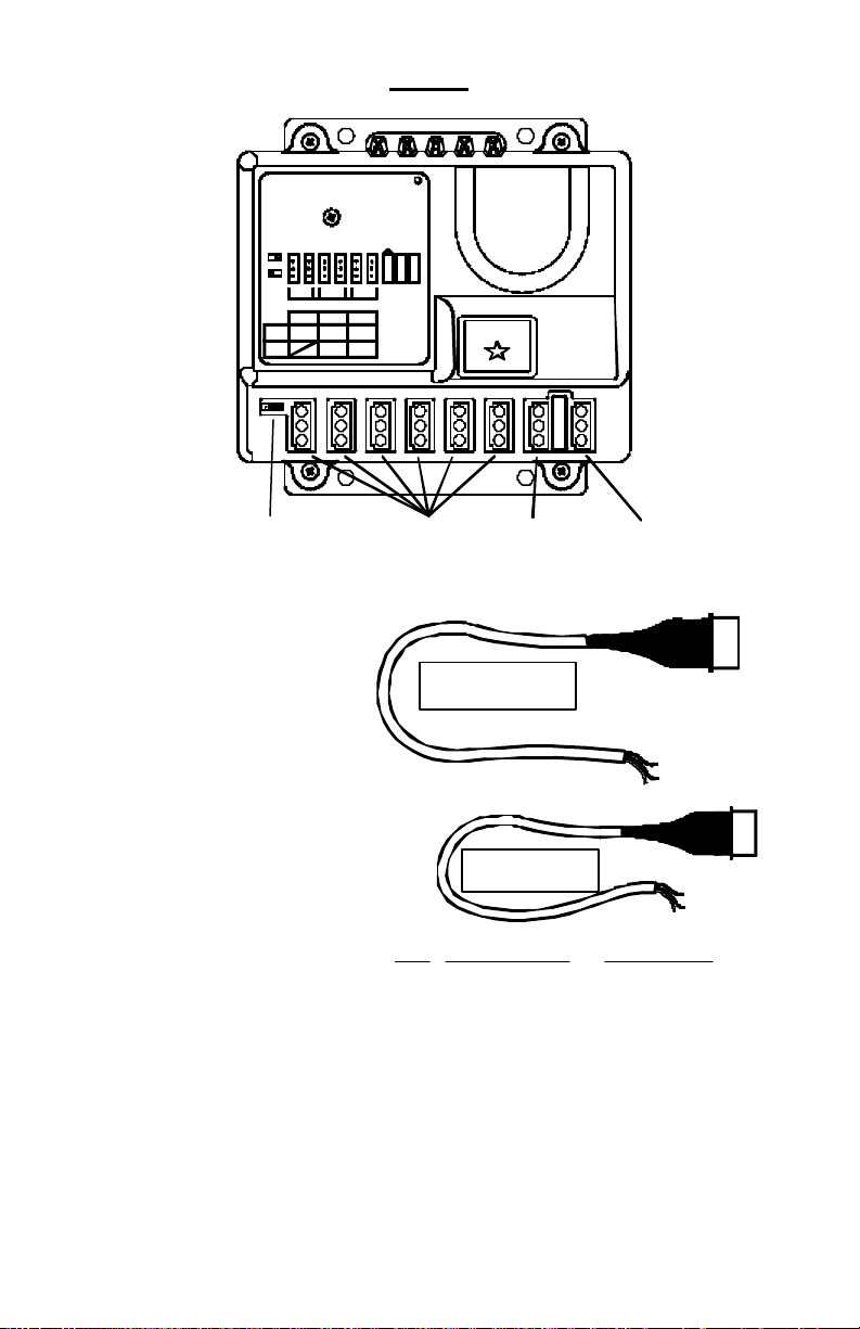
Wiring
R
STAR-PAK
STROBE POWER SUPPLY
RP966/RP996
POS 1
POS 2
3-41-2 5-6
STROBE HEADS
A
POS 1 1+2 3+4 5+6
HI
POS 2
1 _4 5+6
LOW
HIGH/LOW - HEAD
SELECT JUMPER
B
C
PATTERN
SELECT
+
A
I
P
B
15
-
+
C
I
+
+
FUSE
POWER
ENABLE
STROBE
OUTLETS
STATUS
POWER
PLUG
ENABLE
PLUG
POWER Plug
The power plug is included with
your power pack and comes
complete with an 8-12” wiring
harness. This will be connected to
the outlet on your pack labeled
POWER.
POWER PLUG FOR
RP966 AND RP996
Red = Power
Black = Ground
White = Pattern Select
PLUG
POWER
ENABLE Plug
These strobe packs also utilize
another plug, identical to the Power
Plug, which plugs into the jack
labeled ENABLE. The connection
ENABLE PLUG FOR
RP966 AND RP996
of the ENABLE wires will allow you
to set the pack up in a number of
different configurations. Here are
the different configurations you
may choose from when installing
the RP966 and RP996 packs:
• All 6 Heads On and Off Together (High Power Only)
Wire Jumper Set For Jumper Set For
Color 3-Pair Head Select High/Low Option
Red = Enable Heads 5 & 6 Enable Heads 5 & 6
Black = Enable Heads 3 & 4 Enable Heads 1, 2, 3, & 4
White = Enable Heads 1 & 2 High/Low Option Switching
• All 6 Heads On and Off Together (Low Power Only)
• All 6 Heads On and Off Together (High/Low switching Option)
• 2-Heads/4-Heads Separate Activation (High Power Only)
• 2-Heads/4-Heads Separate Activation (Low Power Only)
• 2-Heads/4-Heads Separate Activation (High/Low Switching Option)
• 3-Pair Separate Activation (High Power Only)
Decide which configuration will work best for you, set your jumper accordingly (see next
page), and proceed to the appropriate section to connect the wires from the POWER and
ENABLE connectors.
-3-
PLUG
ENABLE
Page 6
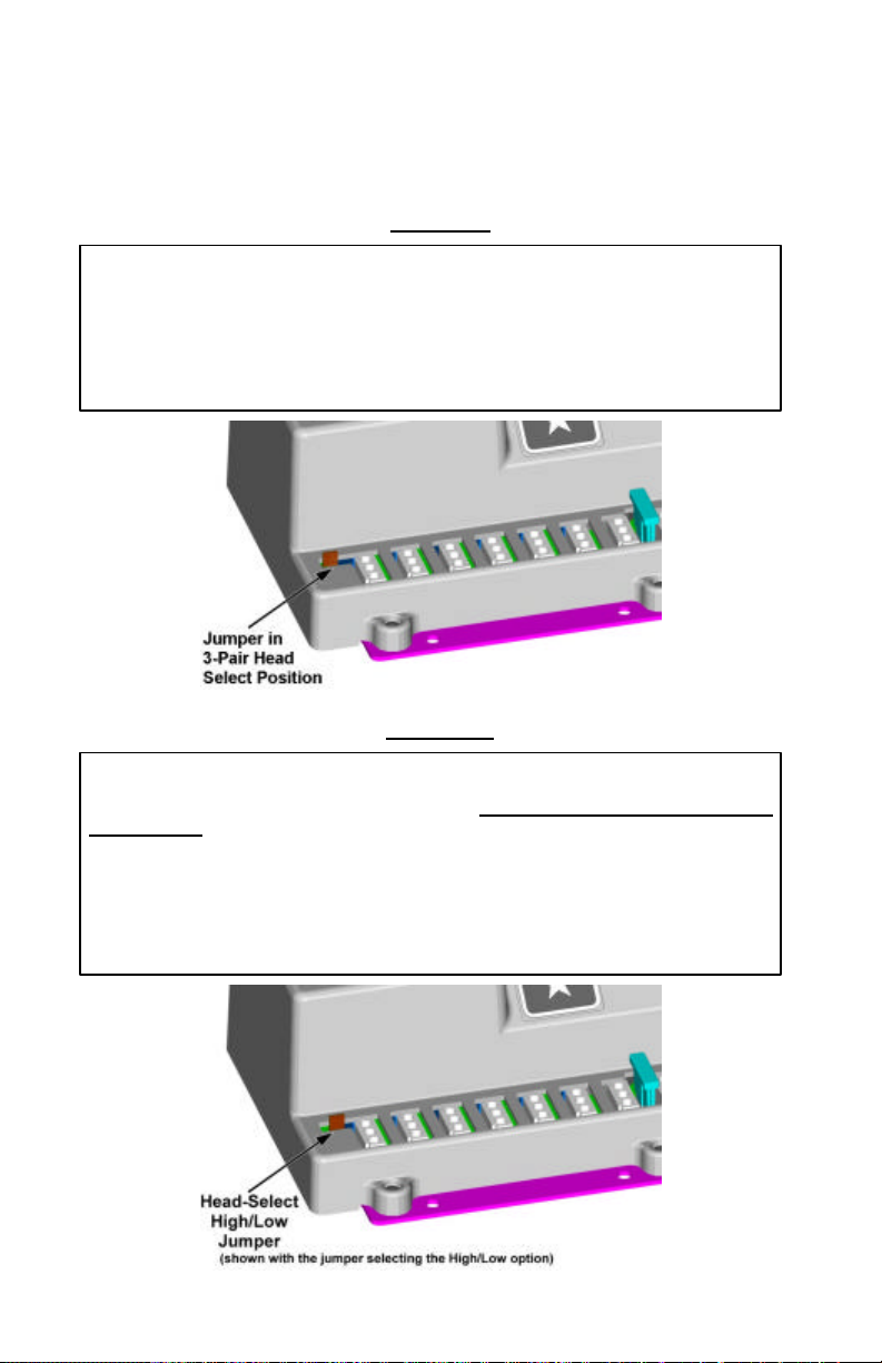
Setting the High/Low – Head Select Jumper
If you wish to activate three separate pairs of heads i
ndependently of each other,
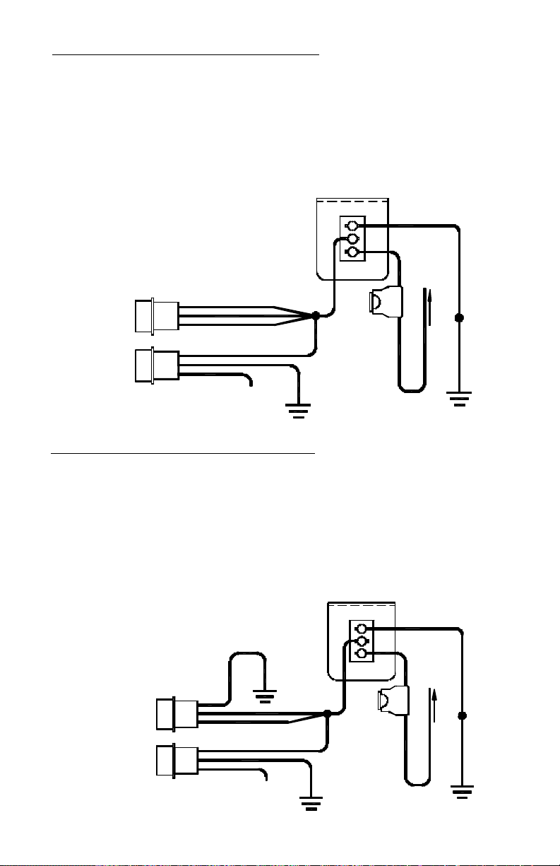
If you would like to utilize both high and low power, or you will be activating
all 6 of
The RP966 and RP996 remote strobe packs allow you to choose whether you would prefer
to have the ability to switch three pairs of heads On/Off separately OR if you would like the
ability to switch between High and Low power, switching two heads separate from the other
four heads. Prior to installation, you should decide which setting will work best for you, and
set the jumper appropriately.
leave the Head Select - High/Low Jumper in the 3 -Pair Head Select position (default)
shown below. The jumper should be on the left two pins, closest to the edge of the
pack. The ENABLE wires will function as follows:
White = Enable Heads 1 & 2
Black = Enable Heads 3 & 4
Red = Enable Heads 5 & 6
your strobe heads together with one On/Off switch, or if you will be activating two
heads independently of the other four heads and do not need to operate three different
pairs of heads, the jumper should be moved to the right two pins, towards the center of
the pack. This will allow you to switch one pair of heads on one switch, the other four
heads on another switch, and select high or low power on a third switch. The ENABLE
wires will function as follows:
Black = Enable Heads 1, 2, 3, & 4
Red = Enable Heads 5, & 6
White = High/Low Option Switching
LEFT POSITION
RIGHT POSITION
-4-
Page 7
GROUND
All Heads On and Off Together (High Power Only)
(This setup is typically used for most “On/Off” applications)
For this set up, only one On/Off switch (not included) is necessary.
1. Connect the black wire from the POWER connector to a good chassis ground.
2. Connect all three wires (red, black, and white) from the ENABLE plug and the red wire
from the POWER connector to a +12VDC power source through your On/Off switch.
3. The white wire from the POWER connector will be left unconnected for now. Once your
system is installed, the white wire will be used to program the flash pattern. Proceed to
the Pattern Selection section on page 8.
RP966/RP996
All Heads Activate Together
High Power Only
(Set Jumper in
High/Low Option Position)
WHITE
ENABLE
CONNECTOR
POWER
CONNECTOR
All Heads On and Off Together (Low Power Only)
For this set up, only one On/Off switch (not included) is necessary.
1. Connect the black wire from the POWER connector and the white wire from your
ENABLE plug to a good chassis ground.
2. Connect the red and black wires from the ENABLE plug and the red wire from the
POWER connector to a +12VDC power source through your On/Off switch.
3. The white wire from the POWER connector will be left unconnected for now. Once your
PLUGS
BLACK
INTO
POWER
PAK
RED
RED
PLUGS
BLACK
INTO
POWER
PAK
WHITE
Pattern Select:
Touch and release to +12VDC
to set pattern then tape off
SP3860-1-15 LIGHTED SWITCH PANEL
GOOD
CHASSIS
GROUND
RED
ON
3
232
1
1
OFF
SW1
(REAR VIEW)
FUSE
15 AMP
CONNECT TO +12 VDC
BLACK
GOOD
CHASSIS
system is installed, the white wire will be used to program the flash pattern. Proceed to
the Pattern Selection sect ion on page 8.
All Heads Activate Together
ENABLE
CONNECTOR
POWER
CONNECTOR
RP966/RP996
Low Power Only
(Set Jumper in
High/Low Option Position)
WHITE
PLUGS
BLACK
INTO
POWER
PAK
RED
RED
PLUGS
BLACK
INTO
POWER
PAK
WHITE
Pattern Select:
Touch and release to +12VDC
to set pattern then tape off
GOOD
CHASSIS
GROUND
SP3860-1-15 LIGHTED SWITCH PANEL
ON
3
3
2
2
1
1
(REAR VIEW)
OFF
SW1
GOOD
CHASSIS
GROUND
RED
FUSE
15 AMP
BLACK
CONNECT TO +12 VDC
GOOD
CHASSIS
GROUND
-5-
Page 8

All Heads On and Off Together
(With High/Low Power Switching Option)
1. Use Star Model #SP3860-2H-OP switch panel (not included), or any other standard two-
switch switch panel capable of delivering 15 amps.
2. Connect the black wire from the POWER connector to a good chassis ground.
3. Connect the black and red ENABLE plug wires and the red POWER plug wire to +12VDC
through the first On/Off switch .
4. The white wire from the ENABLE plug allows utilization of the High//Low (Day/Night
Mode) option. The white wire from your ENABLE plug should be connected to the second
switch. When the white wire is connected to power through your second switch, the
pack will run in high power mode. When the second switch is in the “off” position, yo ur
pack will operate in “Night Mode” (low power).
5. The white wire from the POWER connector will be left unconnected for now. Once your
system is installed, the white wire will be used to program the flash pattern. Proceed to
the Pattern Selection sect ion on page 8.
All Heads Activate Together
(Set Jumper in High/Low Option Position)
RP966/RP996
With High/Low Option
ENABLE
CONNECTOR
POWER
CONNECTOR
WHITE
PLUGS
BLACK
INTO
POWER
PAK
RED
RED
PLUGS
INTO
BLACK
POWER
PAK
WHITE
Pattern Select:
Touch and release to +12VDC
to set pattern then tape off
SP3860-2H-OP LIGHTED SWITCH PANEL
ONHIGH
BLUE
GOOD
CHASSIS
GROUND
3
2
SW2
RED
3
2
11
OFFLOW
SW1
15 AMP
(REAR VIEW)
FUSE
CONNECT TO +12 VDC
BLACK
GOOD
CHASSIS
GROUND
2-Head/4-Head Separate Activation (High Power Only)
(diagram on next page)
1. For this set up only two On/Off switches are necessary (not included). Use Star Model
#SP3860-2 switch panel, or any other standard two-switch switch panel capable of
delivering 15 amps.
2. Connect the black wire from the POWER connector to a good chassis ground.
3. Connect the red wire from the ENABLE plug to +12VDC through your first switch.
4. Connect the black wire from the ENABLE plug to +12VDC through your second switch.
5. Connect the red wire from the POWER plug and the white wire from the ENABLE plug
to +12VDC through a 15 amp fuse (not included).
Please Note: When the red POWER wire is connected to +12VDC the pack will draw a
small current (50 mA). If your vehicle will be sitting for extended periods of time (i.e.
more than a few days), it is recommended that all +12VDC wires be routed through an
ignition switched power source.
6. The white wire from the POWER connector will be left unconnected for now. Once your
system is installed, the white wire will be used to program the flash pattern. Proceed to
the Pattern Selection section on page 8.
-6-
Page 9
2-Head/4-Head Separate Activation (High Power Only) (CONT’D)
is recommended that all
+12VDC wires
be routed through an ignition switched power source.
Two-Head/Four-Head Switching
(Set Jumper in High/Low Option Position)
ENABLE
CONNECTOR
POWER
CONNECTOR
Please Note: When the red POWER wire is connected to
+12VDC the pack will draw a small current (50 mA).
If your vehicle will be sitting for extended periods of time (i.e. more than a few days), it
is recommended that all +12VDC wires be routed through an ignition switched power source.
RP966/RP996
High Power Only
RED
PLUGS
BLACK
INTO
POWER
PAK
WHITE
RED
PLUGS
BLACK
INTO
POWER
PAK
WHITE
Pattern Select:
Touch and release to +12VDC
to set pattern then tape off
SP3860-2 LIGHTED SWITCH PANEL (REAR VIEW)
ON
ON
3
3
2
2
11
OFF
OFF
SW1
SW2
RED
BLUE
FUSE
15 AMP
CONNECT TO +12 VDC
FUSE
15 AMP
BLACK
CONNECT TO +12 VDC
GOOD
CHASSIS
GROUND
2-Head/4-Head Separate Activation (Low Power Only)
1. For this set up, only two On/Off switches are necessary (not included). Use Star Model
#SP3860-2 switch panel, or any other standard two-switch switch panel capable of
delivering 15 amps.
2. Connect the black wire from the POWER connector and the white wire from the
ENABLE plug to a good chassis ground.
3. Connect the black wire from the ENABLE plug to +12VDC through your second switch.
4. Connect the red wire from the ENABLE plug to +12VDC through your first switch.
Please Note: When the red POWER wire is connected to +12VDC the pack will draw a
small current (50 mA). If your vehicle will be sitting for extended periods of time (i.e.
more than a few days), it is recommended all +12VDC wi res be routed through an
ignition switched power source.
5. The white wire from the POWER connector will be left unconnected for now. Once your
system is installed, the white wire will be used to program the flash pattern. Proceed to
the Pattern Selection section on page 8.
RP966/RP996
Two-Head/Four-Head Switching
Low Power Only
(Set Jumper in High/Low Option Position)
WHITE
ENABLE
CONNECTOR
POWER
CONNECTOR
PLUGS
INTO
POWER
PLUGS
INTO
POWER
PAK
PAK
Please Note: When the red POWER wire is connected to
+12VDC the pack will draw a small current (50 mA).
If your vehicle will be sitting for extended periods of time (i.e. more than a few days), it
WHITE
BLACK
RED
RED
BLACK
WHITE
Pattern Select:
Touch and release to +12VDC
to set pattern then tape off
SP3860-2 LIGHTED SWITCH PANEL (REAR VIEW)
ON
ON
3
3
2
2
11
OFF
SW2
BLUE
GOOD
CHASSIS
GROUND
OFF
SW1
RED
FUSE
15 AMP
CONNECT TO +12 VDC
GOOD
CHASSIS
GROUND
FUSE
15 AMP
CONNECT TO +12 VDC
GOOD
CHASSIS
GROUND
BLACK
-7-
Page 10

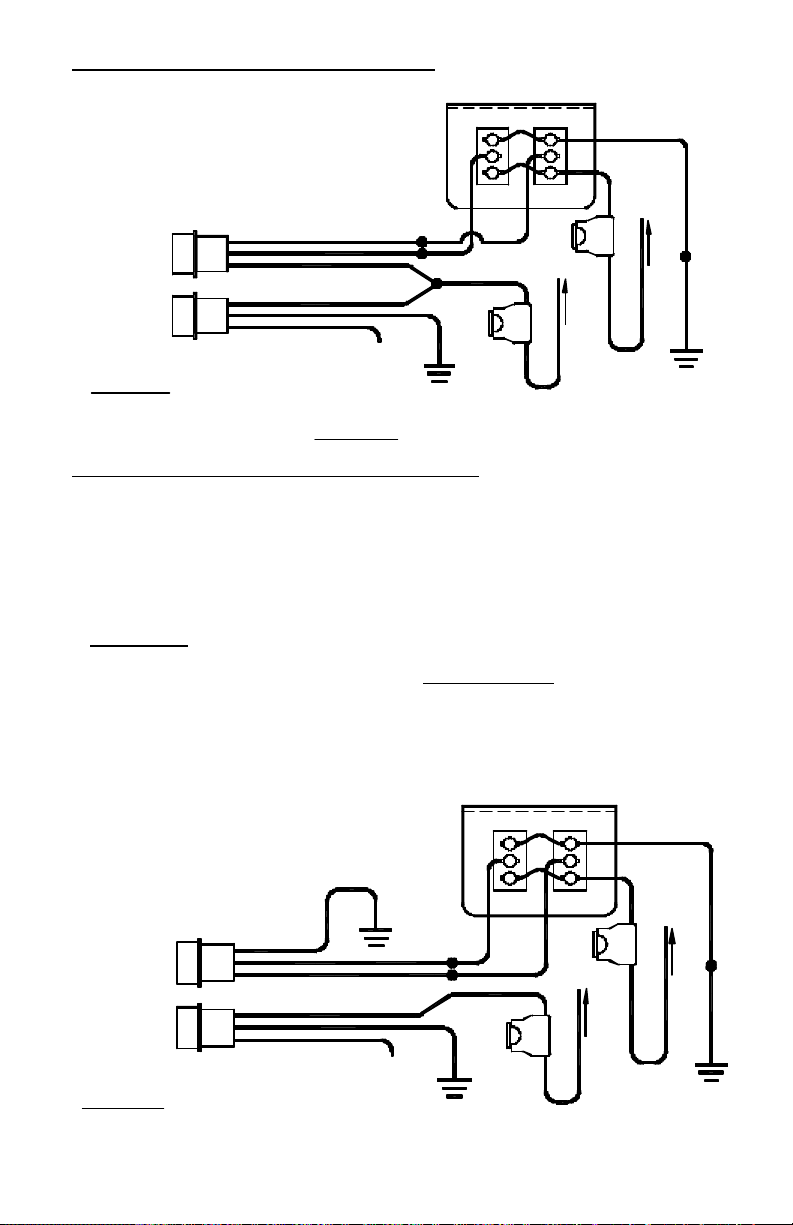
2-Head/4-Head Separate Activation (With High/Low Power Switching Option)
1. Simultaneous Singleflash
or
3-Pair Independent Activation (High Power Only)
(diagram on next page)
1. Use Star Model #SP3860-3 switch panel (not included), or any other standard three -switch
switch panel capable of delivering 15 amps.
2. Connect the black wire from the POWER connector to a good chassis ground.
3. Connect the red wire from the ENABLE plug to +12VDC through your first switch.
4. Connect the black wire from the ENABLE plug to +12VDC through your second switch.
5. Connect the white wire from the ENABLE plug to +12VDC through your third switch.
If the Head Select/High-Low Jumper is in the High/Low position: (see page 4)
The white wire from the ENABLE plug allows utilization of the High/Low (Day/Night
Mode) option. The white wire from your ENABLE plug should be connected to the third
switch. When the white wire is connected to power through your third switch, the pack
will run under high power (Day Mode). When the third switch is in the “off” position, your
pack will operate under low power (Night Mode).
If the Head Select/High-Low Jumper is in the 3-Pair Head Select position: (see page 4)
The pack will run under high power and each switch will control one pair of heads.
6. The white wire from the POWER connector will be left unconnected for now. Once your
system is installed, the white wire will be used to program the flash pattern. Proceed to
the Pattern Selection section on below.
1. The white wire on the POWER cable for the RP966 and RP996 packs allows you to
select what pattern you would like the strobe heads to exhibit.
2. Once your switch, strobe pack, cables, and heads are installed, activate your strobe
system by turning all the switches on.
3. Using the white wire on the POWER cable, select your flash pattern by slowly touching it
to +12VDC for about two seconds and releasing it. Continued touching for two seconds
and releasing of the white wire to +12VDC will scroll through the following 24 different
patterns:
2. Alternating Single flash
3. Alternating Doubleflash
4. Alternating Tripleflash
5. Alternating Quadflash
6. Alternating Quintflash
7. Double-Duty
8. Doubleflash Alternating,
Doubleflash Simultaneous
9. Alternating Climber
10. Leadfoot
11. Singleflash Knight Rider Effect†
12. Quadflash Knight Rider Effect†
13. Doubleflash Left†
Pattern Selection
4. Once you have found the desired pattern, you can turn off the system. The strobe
pack will “remember” the last selected pattern when switched off and that pattern will
be displayed the next time the pack is switched on. Tape or place a wirenut over the
end of the white wire to prevent it from coming into contact with +12VDC again.
5. OPTIONAL: If you wish to utilize your own remote pattern select switch, you may
connect the white wire to +12VDC through a momentary on/off switch (user supplied).
14. Doubleflash Right†
15. Quadflash Center Out †
16. Quadflash Warning†
17. Pseudo-Random
18. Delta Omega Sweep
19. Alternating Quadflash & Alternating Single flash Combo
20. Delta Om ega Sweep, Alternating Quintflash &
Alternating Doubleflash Combo (DEFAULT)
21. Alt. Doubleflash, Simultaneous Doubleflash, Leadfoot,
Pseudo-Random & Alt. Quadflash Combo
22. Alternating Climber, Double-Duty, Alternating
Quintflash & Alternating Quadflash Combo
23. Cycle Through Patterns 1 - 10, 17 & 18
24. Cycle Through All Patterns
† - Traffic Director type patterns - with only two heads
enabled, these patterns will all be Quadflash Warn.
-8-
Page 11

BLACK
CONNECT TO +12 VDC
FUSE
15 AMP
312
ON
(High Power Only)
ON
3
HIGH/ON
Three-Pair Independent Switching
SP3860-3 LIGHTED SWITCH PANEL (REAR VIEW)
213
2
OFF
OFF
1
LOW/OFF
SW1
SW2
SW3
RED
BLUE
ORANGE
or
RP966/RP996
GOOD
CHASSIS
GROUND
CONNECT TO +12 VDC
FUSE
15 AMP
GOOD
CHASSIS
GROUND
RED
WHITE
BLACK
PAK
INTO
PLUGS
POWER
SW1 will enable heads 5 & 6
SW2 will enable heads 1, 2, 3, & 4
SW3 will switch between High and Low Power
SW1 will enable heads 5 & 6
SW2 will enable heads 3 & 4
With the Jumper in the High /Low Option Position
(With High/Low Option)
SW3 will enable heads 1 & 2
With the Jumper in the 3-Pair Head Select Position
ENABLE
Two-Head/Four-Head Switching
CONNECTOR
BLACK
WHITE
RED
PAK
INTO
PLUGS
POWER
POWER
CONNECTOR
Pattern Select:
Touch and release to +12VDC
to set pattern then tape off
-9-
will be sitting for extended periods of time (i.e. more than a few days), it is recommended that all +12VDC wires
be routed through an ignition switched power source.
Please Note: When the red POWER wire is connected to +12VDC the pack will draw a small current (50 mA). If your vehicle
Page 12

1. The RP966 and RP996 power packs come with a built-in “star-shaped” status LED.
Status LED
2. When operating properly, the LED will blink in conjunction with each of the strobe
heads.
3. If none of the heads are flashing and the Star LED is a dim steady burn, proper
voltage is reaching the POWER cable, but is not reaching the ENABLE cable. Check
that your switches are on and that +12VDC is reaching the ENABLE wires.
4. The Star LED is also designed to flicker when there are no active strobe heads
flashing during a particular flash cycle. If none of the heads are flashing and the LED
is flickering, all of the heads are bad or they are all wired incorrectly.
5. If none of the heads are flashing and the Star LED single flashes every 1 -3 seconds
then the pack is receiving insufficient voltage (below 11.0 volts).
-10-
Page 13

Remote Power Pack Cabling Requirements
Length (ft)
Shielded Cable
SO Cable
Length (ft)
Shielded Cable
SO Cable
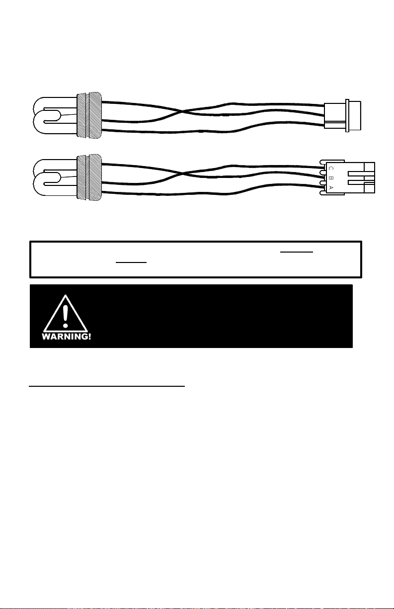
1. Cable is required to connect the power pack to your remote strobe heads. Cable can
be purchased from Star:
w/Amp w/Weatherproof
Connector Connector
15 4415 3814-180”
20 4420 3814-240”
25 4425 3814-300”
30 4430 3814-360”
35 N/A 3814-420”
w/Amp w/Weatherproof
Connector Connector
40 N/A 3814-480”
45 N/A 3814-540”
50 N/A 3814-600”
55 N/A 3814-660”
60 N/A 3814-720”
2. If you intend to use your own cable for connecting the remote heads, it must meet the
following specifications: It must be three-conductor with 600V insulation, it must be a
minimum 18 AWG for 0-30 ft. or 16 AWG for 31-60 ft., and it should be UV stabilized.
Star does not recommend the use of any cable length greater than 60 feet, as the
resistance may cause a drop in voltage resulting in inconsistent or complete loss of
firing in the heads. Please use the Table below for proper cable sizes.
Input Power and RP966:
Ground Wires RP996:
0-20 ft. 21-30 ft. 31-60 ft
Wires to
Remote Heads
Enable Wires
16 AWG
14 AWG
18 AWG 18 AWG 16 AWG
18 AWG 18 AWG 18 AWG
14 AWG
12 AWG
12 AWG
10 AWG
3. If you are using your own cable and need connectors to attach the cable to the power
pack, order part #CK473. The #CK473 consists of one connector (30041 -20) and
three male terminals (30042-16). This is also the replacement connector for any
remote heads with the white AMP connectors (NOT weatherproof).
4. The AMP connector, found on the cables, which mates to the CK473 is a kit #CK472.
The #CK472 consists of one connector (448) and three female terminals (30042-15).
5. If you need a weatherproof connector kit for your cable to attach to our remote strobe
heads, please order part #CK702. This kit contains one connector (30185-3), three
female terminals (30042-30), and three rubber seals (30186-2).
6. If you need to order a weatherproof connector kit for your strobe head to mate with the
connector on your cable (#CK702), please order part #CK703. This kit contains one
connector (30185-4), three male pins (30042-29), and three rubber seals (30186-2).
7. For good, reliable connections between the cable system and the strobe heads in
various weather and contamination conditions, it is strongly recommended that
dielectric grease be used on the connectors. It should be applied to the rear of the
connectors, where the wires enter, as well as into each terminal area where the
connectors mate, before joining the two connectors together. We have found this
procedure to be effective even under the most extreme of conditions. Do Not Seal
The Connectors Using Silicon Or RTV.
Connecting the Remote Heads:
-11-
Page 14

If a problem exists in only one head, a strobe tube may have burned out, or there
may be an open electrical connection in the wiring harness or strobe head. Check
connections at and between the strobe pack and the strobe head, including all
wiring. Replace the malfunctioning heads and/or wiring harnesses if necessary.
If none of your heads are flashing, follow these steps to determine the problem:
1. Check all fuses, including those at the battery, at the switch panel, in the
dash, and on the pack (if applicable). The RP966 and RP996 have
automotive “blade” type fuses. Remove these fuses, and check them to
confirm they have not blown. Replace any blown fuses with only fuses of
identical values. Replacing the fuse with the wrong rating may damage your
pack and/or vehicle, and will void your warranty .
2. Check the power and ground wires to your pack. With the vehicle turned
off and while the pack is running, measure the voltage across the red wire
(pin 1) and the black wire (pin 2) of the POWER connector on the strobe
pack. Push the probes of the test meter down into the connector at the wire
entry points to contact the terminals for the measurement. A nominal 13.8
volts should be present. Low voltage to the pack can cause erratic flashing
or even complete failure of the heads. A minimum of 11.0 volts should be
present for the pack to operate properly.
If you do not have proper voltage present your power or ground is bad. Skip
to the section on Checking a Bad Power or Ground Connection.
If your pack is receiving sufficient voltage then continue to step 3.
3. Check the Power connector to be sure that +12VDC is not applied to
the white wire. The white wire is used for pattern select. The patterns are
changed by touching AND RELEASING this wire to +12VDC. A constant
voltage applied to the white wire on the Power connector will prevent the
strobe pack from flashing.
4. Check that the proper voltage is reaching the necessary ENABLE
inputs.
The black and red wires on the ENABLE plug should have +12VDC. The
white wire should also have +12VDC if the jumper is set for 3-Pair Head
Select (see pages 4 and 9).
TROUBLESHOOTING GUIDE
-12-
Page 15

5. Check each head. If the leads in one of the heads have shorted out, the
output voltage of the other heads may be held down as well. To test for this,
unplug all of the heads and plug them in individually (one at a time). If your
problem is a result of a shorted head, then each good head should function
properly when connected by itself. Note: A burned out strobe tube does not
cause a short and will not affect the operation of the remaining heads. If the
problem is not with a shorted head and if proper voltage is reaching the
pack, the problem is most likely internal to the pack. Call Star to obtain an
R.G.A. number to return the pack for service.
Checking a Bad Power or Ground Connection
If sufficient voltage is not reaching the pack, perform the following tests:
1. Test Power at the Battery: With the vehicle turned off and while the pack is
running, measure the battery voltage at the battery. A nominal 13.8 volts
should exist. If this voltage is below 11.0 volts, the pack will not function
properly and the problem is with the battery. This reading should not be
more than 1.25 volts higher than the reading at the strobe pack itself.
2. Test the Power Wire Between the Battery and the Switch: Move to the
ON/OFF switch in the cab and gain access to the rear of the switch panel.
With the vehicle not running and the pack on at the high power setting,
measure the voltage drop in the red wire by taking a read ing with one probe
on the positive side of the battery and the other probe in pin 1 of your switch.
If this reading exceeds 0.25 volts then there is a poor connection between
the switch and the battery in the red wire and it should be checked. NOTE:
Excessive voltage drop may be occurring in the connections on the switch
panel. If you have one of our switches you can increase the contact
pressure by removing the FASTON terminal from the tab on the switch.
Using long nose pliers, gently squeeze the FASTON terminal together in the
area that slides on to the tab of the switch. This will increase the pressure
applied between the tabs and the connector and reduce voltage drop.
3. Test the Power Wire Between the Strobe Pack and the Switch: This
same procedure can be used to check the wires between the switch panel
and the pack. Place one probe on the terminal at the switch and the other
probe into the terminal with the corresponding wire color in the PWR
connector on the pack. Once again, if any of the readings exceed 0.25 volts
then you should check those wires and their connections.
4. Test your Ground Wire: If you still have not located the problem,
troubleshoot the connections between the good chassis ground and pin 2
(black or blue wire) of the PWR connector on the power pack. With the
vehicle not running and the pack on at the high power setting, measure the
voltage drop in the Black (Ground) wire by taking a reading with one probe
on the negative side of the battery and the other probe in pin 2 of your PWR
connector. If this reading exceeds 0.25 volts then you have a bad Ground.
-13-
Page 16

ONE YEAR LIMITED WARRANTY
The manufacturer warrants each new product, under normal use, against factory defects
in material and workmanship for one year after the date of purchase. The owner will be
responsible for returning to the Service Center any defective item(s) with the
transportation costs prepaid. The manufacturer will, without charge, repair or replace at
its option, products, or part(s), which its inspection determines to be defective. Repaired
or replacement item(s) will be returned to the purchaser with transportation costs prepaid
from the service point. A copy of the purchaser's receipt must be returned with the
defective item(s) in order to qualify for the warranty coverage.
Exclusions from this warranty include, but are not limited to, bulbs, strobe tubes, domes,
and/or the finish. This warranty shall not apply to any light, which has been altered, such
that in the manufacturer's judgment, the performance or reliability has been affected, or if
any damage has resulted from abnormal use or service. This warranty does not apply to
defect or damage occurring as a result of disaster, accident, abuse, misuse, lightning,
power surges, or failure to follow instructions in any enclosed manuals. Any damage or
defects occurring as a result of any unauthorized service or repairs by unauthorized
persons shall be excluded from this warranty.
There are no warranties expressed or implied (including any warranty of merchantability
or fitness), which extend this warranty period. The loss of use of the product, loss of
time, inconvenience, commercial loss or consequential damages, including costs
of any labor, are not covered. The manufacturer reserves the right to change the
design of the product without assuming any obligation to modify any product previously
manufactured.
This warranty gives you specific legal rights. You might also have additional rights that
may vary from state to state. Some states do not allow limitations on how long an implied
warranty lasts. Some states do not allow the exclusion or limitation of incidental or
consequential damages. Therefore, the above limitation(s) or exclusion(s) may not apply
to you.
If you have any questions concerning this or any other product,
please contact our Customer Service Department at (585) 226-9787.
If a product must be returned for any reason, please contact our Customer Service Department
to obtain a Returned Goods Authorization number (RGA #) before you ship the product to Star.
Please write the RGA # clearly on the package near the mailing label.
-14-
Page 17
MODEL ST415P*
These are HIGH INTENSITY strobes. DO
permanent eye damage may occur.
The ST415P series strobe heads are designed for use as an auxiliary warning
light system. They will not replace your current headlights or Stop-Tail-Turn
lights, but instead will provide an independent, supplementary warning signal.
SAFETY MESSAGE TO INSTALLERS
People’s lives depend on your safe installation of our products. It is important to
read, understand and follow all instructions shipped with our products. In addition,
listed below are some other important safety instructions and precautions you should
follow:
• To properly install this warning light: you must have a good understanding of
automotive electrical procedures and systems, along with proficiency in the
installation and use of safety warning equipment.
• When drilling into a vehicle structure, be sure that both sides of the surface are
clear of anything that could be damaged.
• DO NOT install equipment or route wiring or cords in the deployment path of an
air bag.
• DO NOT attempt to activate the light while driving in a hazardous situation.
• File this instruction sheet in a safe place and refer to it when maintaining and/or
reinstalling the product.
Failure to follow all safety precautions and instructions may result in property
damage, serious injury, or death to you or others.
REMOTE STROBE HEAD INSTALLATION
3
2
1
ST415P*
ST415P*-W
IMPORTANT: Please read all of the following
instructions before installing your new remote strobe
system.
NOT stare directly into the light while it is
on, as momentary blindness and/or
PLITSTR346 REV. C 11/1/06
Page 18

1. The remote strobe head must be connected to a power pak to operate. You may use our
two-outlet, four-outlet, or six-outlet paks. These heads may or may not work with alternate
brand power paks. The installer accepts any and all liability if this head is used in
conjunction with any unapproved power paks.
2. Locate the light housing you wish to install the head into. If necessary, disassemble the
light housing on the vehicle such that you can gain access to the back of the reflector.
3. Select a location suitable to mount your strobe head. The ideal location is as close to the
focal point of the reflector as possible. The strobe head must be located at least 1” from
any other lights, the lens, and the lens housing, to allow for adequate heat dissipation.
4. After you have checked that both sides of the mounting surface are clear, drill a 1”
hole in the reflector. Be sure to debur both sides of the hole to allow for easier insertion
and so that there is a clean, smooth surface for the strobe head to seal against.
If you have a double walled housing (ie. an outer wall in addition to the inner reflector
wall), you will need to drill through both surfaces to properly mount your new strobe head.
Using a hole saw, drill a 1 1/4" hole in the outer wall. Once through the outer wall, the pilot
drill bit from the hole saw should start the pilot hole in the inner wall. Using the pilot hole
for centering, drill a 1" hole in the inner wall. Be sure to de-bur both sides of the hole to
allow for easier insertion and so that there is a clean, smooth surface for the strobe head
to seal against. It might be necessary to cover the 1 1/4" hole you drilled in the outer wall
to prevent contaminates getting inside the housing.
5. To insert the strobe head, hold the rubber base with your thumb and forefinger. Slowly
twist the base while you push it into the 1” hole. Twisting while pushing helps the cup to
slide into the hole easier and helps ensure the lip on the rubber base “pops” into place
around the rubber housing.
6. Once the strobe head is installed, reassemble the light.
7. Attach the enclosed connector to the head by snapping the terminals on each wire into the
proper slot. Review the diagram below.
BLACK (GROUND)
WHITE (TRIGGER)
BLACK (GROUND)
WHITE (TRIGGER)
RED (HOT)
GROMMET
RED (HOT)
30042-2930186-2
MALE
TERMINAL
30042-16
MALE
TERMINAL
473
FEMALE AMP
CONNECTOR
3
2
1
30185-4
FEMALE WEATHERPROOF
CONNECTOR
8. Once the installation of the heads is complete, connect them to your power pak using the
proper cable:
Amp Connector Weatherproof Connector
Light Duty Cable 3821 3820
Heavy Duty Cable N/A 3814
Shielded Cable 4415 N/A
9. If you intend to use your own cable, it must meet certain specifications as follows: It must
be three-conductor with 600V insulation, minimum 18 AWG for 0-20 ft., 16 AWG for 21-30
ft. or 14 AWG for 31-60 ft. We do not recommend the use of any cable length greater than
60 feet, as the resistance might cause a drop in voltage resulting in inconsistent or
complete loss of firing in the heads.
Page 19
10. For good, reliable connections between the cable system and the strobe head in various
3), three
CK703
FEMALE
MALE
CK472
weather and contamination conditions, it is strongly recommended that a dielectric grease
be used on the connectors. It should be applied and into each terminal area where the
connectors mate, before joining the two connectors together. We also recommend
applying dielectric grease to the back of each connector where the wires enter. We have
found this procedure to be effective even under the most extreme of conditions. Do Not
Seal The Connectors Using Silicon Or RTV.
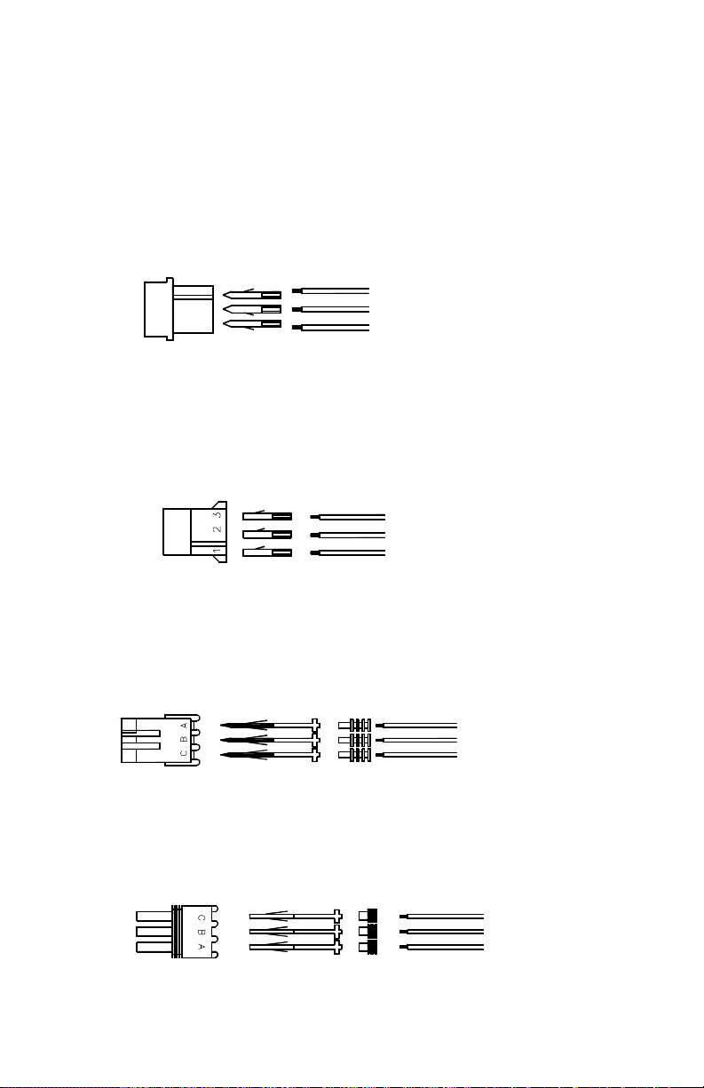
11. If you must remove the white amp connector for any reason, please re-insert the wires
back into their proper location. Please refer to the diagram below. If you need to order
another amp connector kit, please use part #CK473. This kit contains one connector (473)
and three male pins (30042-16).
473
FEMALE
CONNECTOR
1
3 2
30042-16
MALE
TERMINAL
CK473
RED (HOT)
BLACK (GROUND)
WHITE (TRIGGER)
12. If you need to order a white amp connector kit to mate with the CK473 (the connector on
your strobe head), please use part #CK472. This kit contains one connector (448) and
three female pins (30042-15).
448
30042-15
WHITE (TRIGGER)
BLACK (GROUND)
RED (HOT)
13. If you must remove the weatherproof connector for any reason, please re-insert the wires
back into their proper location. Please refer to the diagram below. If you need to order
another weatherproof connector kit, please use part #CK703. This kit contains one
connector (30185-4), three male pins (30042-29), and three rubber seals (30186-2).
30185-4
FEMALE WEATHERPROOF
CONNECTOR
30042-29
MALE
TERMINAL
30186-2
GROMMET
BLACK
WHITE
RED
(HOT)
(GROUND)
(TRIGGER)
14. If you need to order a weatherproof connector kit to mate with the CK703 (the connector on
your strobe head), please use part #CK702. This kit contains one connector (30185female pins (30042-30), and three rubber seals (30186-2).
30185-3
MALE WEATHERPROOF
CONNECTOR
30042-30
FEMALE
TERMINAL
CK702
30186-2
GROMMET
RED (HOT)
BLACK (GROUND)
WHITE (TRIGGER)
Page 20
Please Note: These instructions are provided as a general guideline only. Specific
mounting, wiring, and/or weather-sealing may be necessary and are the sole
responsibility of the installer. The manufacturer assumes no responsibility for the
integrity of the installation for this or any of its products.
Page 21
CK473
1. Enclosed you will find a kit containing 1 cable-side connector and 3 male pins.
2. Cut off the old connector from the cable on your vehicle, if present.
3. Strip 1½"-2" of the outer insulation off exposing the three inner wires.
4. These wires should be stripped each about ¼".
5. Secure each terminal by crimping the large tabs around the insulation and the small tabs around the exposed wire.
6. After checking that your crimps are secure, insert the terminals into the correct holes in the connector as shown above.
473 30042-16
FEMALE
CONNECTOR
TERMINAL
MALE
7. For good, reliable connections between the cable system and the strobe tube head in various weather and contamination conditions, it is strongly
recommended that a dielectric grease be used on the connectors. It should be applied and into each terminal area where the connectors mate,
before joining the two connectors together. We have found this procedure to be effective even under the most extreme of conditions. Do Not
Seal The Connectors Using Silicon Or RTV.
RED OR GREEN (HOT)
BLACK OR BLUE (GROUND)
WHITE (TRIGGER)
PLITSTR133 REV. B 11/24/04
CK473
1. Enclosed you will find a kit containing 1 cable-side connector and 3 male pins.
2. Cut off the old connector from the cable on your vehicle, if present.
3. Strip 1½"-2" of the outer insulation off exposing the three inner wires.
4. These wires should be stripped each about ¼".
5. Secure each terminal by crimping the large tabs around the insulation and the small tabs around the exposed wire.
6. After checking that your crimps are secure, insert the terminals into the correct holes in the connector as shown above.
473 30042-16
FEMALE
CONNECTOR
TERMINAL
MALE
RED OR GREEN (HOT)
BLACK OR BLUE (GROUND)
WHITE (TRIGGER)
7. For good, reliable connections between the cable system and the strobe tube head in various weather and contamination conditions, it is strongly
recommended that a dielectric grease be used on the connectors. It should be applied and into each terminal area where the connectors mate,
before joining the two connectors together. We have found this procedure to be effective even under the most extreme of conditions. Do Not
Seal The Connectors Using Silicon Or RTV.
PLITSTR133 REV. B 11/24/04
CK473
1. Enclosed you will find a kit containing 1 cable-side connector and 3 male pins.
2. Cut off the old connector from the cable on your vehicle, if present.
3. Strip 1½"-2" of the outer insulation off exposing the three inner wires.
4. These wires should be stripped each about ¼".
5. Secure each terminal by crimping the large tabs around the insulation and the small tabs around the exposed wire.
6. After checking that your crimps are secure, insert the terminals into the correct holes in the connector as shown above.
7. For good, reliable connections between the cable system and the strobe tube head in various weather and contamination conditions, it is strongly
473 30042-16
FEMALE
CONNECTOR
TERMINAL
MALE
recommended that a dielectric grease be used on the connectors. It should be applied and into each terminal area where the connectors mate,
before joining the two connectors together. We have found this procedure to be effective even under the most extreme of conditions. Do Not
Seal The Connectors Using Silicon Or RTV.
RED OR GREEN (HOT)
BLACK OR BLUE (GROUND)
WHITE (TRIGGER)
PLITSTR133 REV. B 11/24/04
Page 22
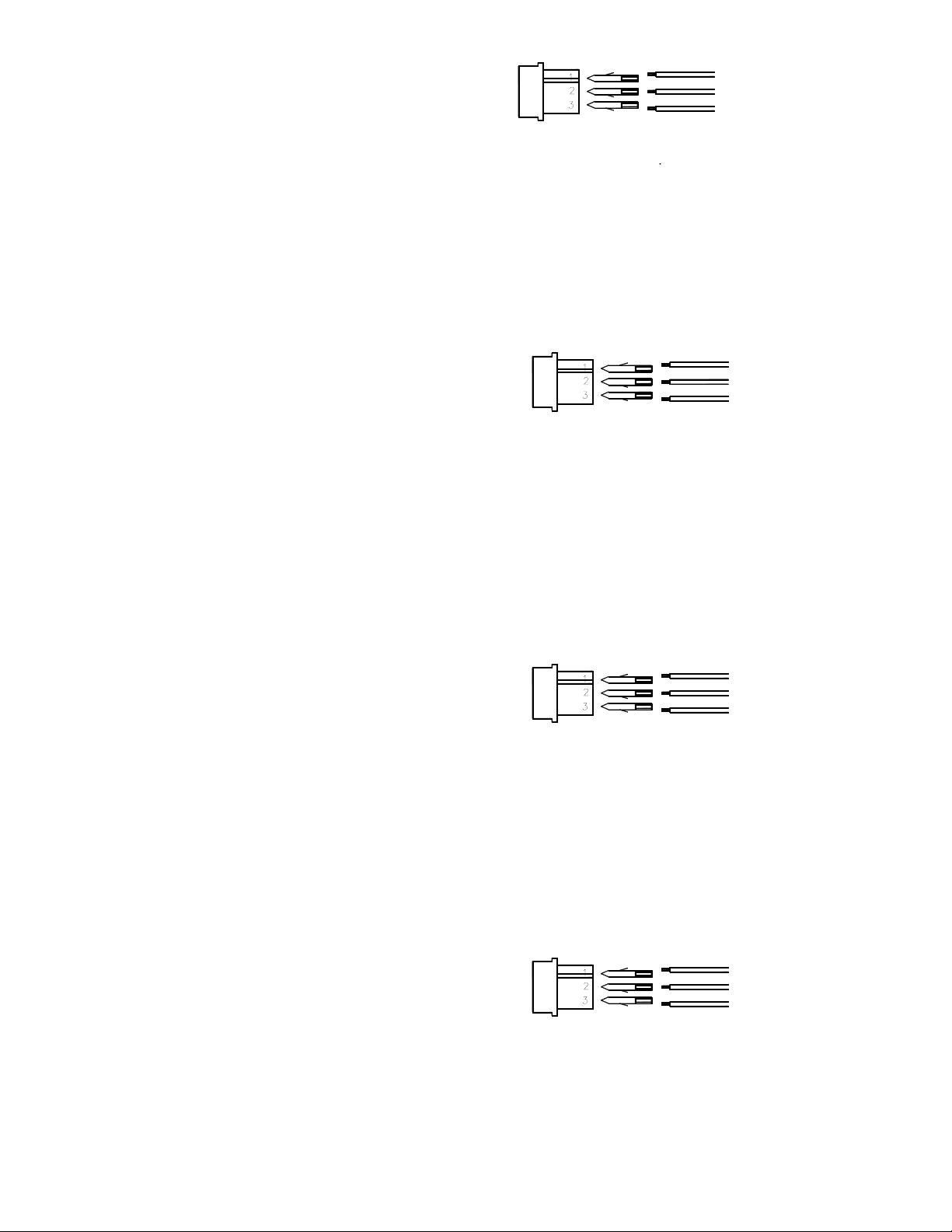
POWER OUT:
POWER PAK
CONNECT TO THE
2
RED WIRE FROM
3
CONNECT
TO +12 VDC
1
(REAR VIEW)
CHASSIS
CONNECT
GROUND
TO A GOOD
Chassis Ground.
1. Connect Terminal 1 shown in the above picture to a Good
wire which supplies power to your power pak.
2. Connect Terminal 2 shown in the picture above to the Red
3. Connect Terminal 3 to your +12 VDC power supply.
on. If you would like to have the switch constantly lit swap the
hook-ups to Terminal 2 and Terminal 3.
4. The above instructions will light the switch when it is turned
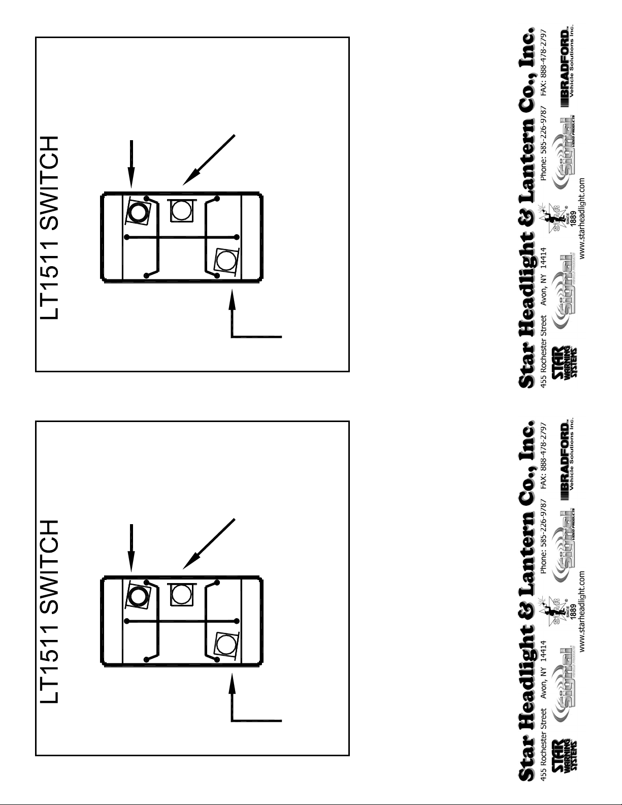
POWER OUT:
2
POWER PAK
RED WIRE FROM
CONNECT TO THE
3
CONNECT
TO +12 VDC
1
(REAR VIEW)
CHASSIS
CONNECT
GROUND
TO A GOOD
Chassis Ground.
1. Connect Terminal 1 shown in the above picture to a Good
wire which supplies power to your power pak.
2. Connect Terminal 2 shown in the picture above to the Red
3. Connect Terminal 3 to your +12 VDC power supply.
on. If you would like to have the switch constantly lit swap
the hook-ups to Terminal 2 and Terminal 3.
4. The above instructions will light the switch when it is turned
REV. - 7/12/02 PLITSTR280 REV. - 7/12/02 PLITSTR280
 Loading...