

Star Headlight & Lantern Mini Phantom ULB9, Mini Phantom ULB9-1, Mini Phantom ULB9S-1, Mini Phantom ULB9S Installation And Instruction Manual
Page 1
INSTALLATION AND INSTRUCTION MANUAL
Star
™
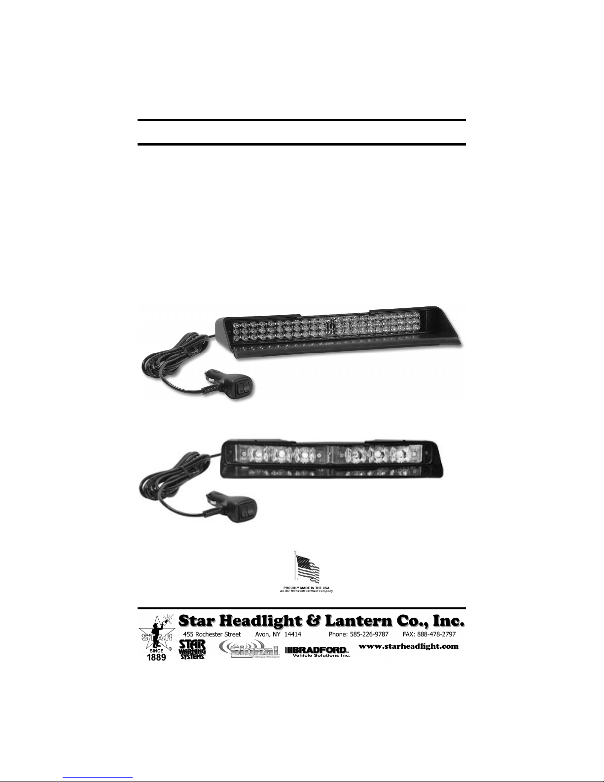
Mini Phantom
35-Pattern Undercover
Interior Mini LED Light
Models ULB9 and ULB9-1
(Discrete LEDs)
Models ULB9S and ULB9S-1
(Starburst LEDs)
PLITSTR46 REV. H 1/26/12
Page 2
IMPORTANT: Please read all of the following instructions before installing your new light.
CAUTION: Please be sure to check that your cigarette plug outlet or hard wire is properly fused
Please Note: These instructions are provided as a general guideline only. Specific
mounting, wiring, and/or weather-sealing may be necessary and are the sole
responsibility of the installer. Signal Vehicle Products assumes no responsibility
for the integrity of the installation for this or any of its products.
with a 5 amp fuse. Testing the light before this fuse is properly installed will void
the warranty on the light.
This light is designed to be mounted on the inside of your vehicle.
It is not intended for exterior applications and is not warranted
against water damage.
It is the sole responsibility of the owner to ensure the warning light is
secure. Check your light every time you enter the vehicle to ensure that
it is mounted securely. The manufacturer assumes no responsibility for
the secure mounting of this light.
The
Mini Phantom
™ uses state-of-the-art Light Emitting Diode
(LED) technology. This warning light is comprised of ultra-high
intensity LEDs that are operated by a micro-controller to efficiently
produce light output with lifetimes up to 100,000 hours.
NOTICE
Due to continuous product improvements, we must reserve the right to change any specifications and information,
contained in this manual at any time without notice. Star Headlight & Lantern Co., Inc. makes no warranty of any
kind with regard to this manual, including, but not limited to, the implied warranties of merchantability and fitness
for a particular purpose. Signal Vehicle Products, Inc. shall not be liable for errors contained herein or for
incidental or consequential damages in connection with the furnishing, performance, or use of this manual.
-i-
Page 3
General
Typical mounting locations for the
vehicle, in the rear window, on the rear deck, or directed out the side window.
Mini Phantom
™ include the front windshield of a
While there is no specific “top” or “bottom” to the light, nor a specific “right” or “left” side, you
still must take into account which mount you will be using and which way the main bracket
should be mounted to the rear of the light, based on where you are going to mount the light
and where you will run the cord.
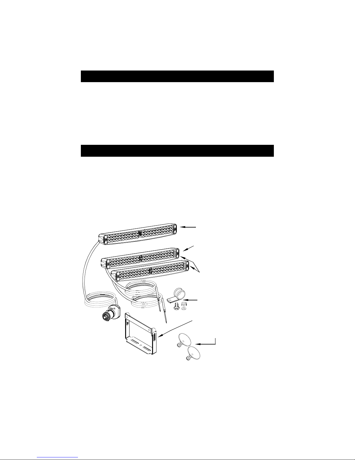
Parts
This package should contain the following:
1 ULB9, ULB9S, ULB9-1, or ULB9S-1 LED Light
1 274-ULB9BKT that includes the following:
1 ULB9-BKT Mounting Bracket set
1 274-ULB9MMC Mirror Mounting Clamp
2 DL15-CUP Suction Cups
ULB9-* or ULB9S-* [*=color(s)]
Cig Plug Version
(Includes 274-ULB9MMC, ULB9-BKT,
and (2) DL15-CUP)
ULB9-1-* or ULB9S-1-* [*=color(s)]
Hard Wired Version
(Includes 274-ULB9MMC, ULB9-BKT,
and (2) DL15-CUP)
RLKULB9-1-* or RLKULB9S-1-* [*=color(s)]
Kit containing:
(2) ULB9-1 Lights
(2) 274-ULB9BKT
274-ULB9MMC
(Includes clamp, bolt,
nut, and washer)
ULB9-BKT
(Includes four Philips head screws, two
flat washers, and two tooth washers)
DL15-CUP (qty=2)
-1-
Page 4

Mounting
1. The
Mini Phantom
mounted in the front windshield of a
vehicle, in the rear window, on the
rear deck, or directed out the side
window. All of the mounts will
require you to attach the mounting
bracket to the light.
2. Based on where you are going to
mount the light and where you will
run the cord, determine which
direction you will mount the ULB9BKT to your light. Attach Part A of
the mounting bracket, facing the
direction you have selected, to the
light by using two Philips head
screws.
CAUTION: Take extreme caution not to over tighten the screws!!! Over
tightening of the screws can strip the holes and result in a faulty mount.
3. Once Part A is secured to the light, use two Philips head screws, two flat washers, and
two tooth washers to attach Part B of the mounting bracket to Part A.
(See the diagram below for proper installation of the washers.)
CAUTION: Take extreme caution not to over tighten the screws!!! Over
tightening of the screws can strip the holes and result in a faulty mount.
4. If you are mounting the light directly to the
rear deck, dash, or other suitable surface,
you may use appropriate fasteners (not
supplied) to attach the bracket to your
mounting surface. Skip to step 10.
B
™ can be
A
A
A
MOUNT
THROUGH
BRACKET
-2-
Page 5

5. If you are utilizing the suction
cup mount, attach the DL15CUP suction cups to the
mounting bracket. Then mount
the light in the desired location
and skip to step 10.
274-ULB9MMC
8. Place the 274-ULB9MMC clamp around the mirror stem.
6. If you are using the 274-ULB9MMC to mount your
Phantom
the installer to ensure that the rear view mirror mount can support
the light you are installing.
7. Remove the 274-ULB9MMC clamp, nut, bolt, and washer from the
hardware kit.
™ to your rear view mirror, it is the sole responsibility of
Take extreme caution not to
over tighten the suction cups!!!
Over tightening of the screws
can strip the holes or puncture
the inside of the cup and result
in a faulty mount.
CAUTION:
Mini
10. Once the light is secured, route your cord such that it does not interfere with the vision of the
driver or the operation of the steering wheel, gear shifter, and/or any airbags.
9. Attach the clamp to the ULB9-BKT with the washer, nut
and bolt, securing your light to the rear view mirror.
-3-
Page 6

ULB9 and ULB9S Connections and Operation
ULB9/9S (cig plug version only)
The ULB9 (cig plug version) can be left plugged into the
cig plug outlet in your vehicle. It can be turned on and off
using the lighted power switch on the cord.
The pattern select switch is used to preset the desired
pattern. You can cycle through the different patterns by
briefly pressing the pattern select switch and releasing it.
The ULB9 has 35 patterns to choose from. After the final
pattern is reached, the patterns will cycle through again.
PLEASE NOTE: THIS IS DIFFERENT THAN THE ULB9-1, WHICH HAS ONLY 3 PATTERNS.
ULB9/9S Patterns
1. Slow Warn
2. Alt. Doubleflash, Flicker
3. All Double, Alt. Pre-Pop Triple, Slow Warn
4. Alternating Doubleflash, Non-Synch
5. Alt. Triple, Alt. Pre-Pop Triple, Flicker *
6. Alt. Quad, Flicker, Alt. Double, Flicker
7. Alt. Pre-Pop Quint, Alt. Quint, Flicker
8. All Tripleflash
9. Alt. Quadflash w/Post Pop
10. All Quadflash w/Post Pop
11. Alt. Quintflash
12. One Side Steady/Other Side Singleflash †
13. Alt. Pre-Pop Quintflash
14. All Flicker
15. Alt. PSU Flicker
16. One Side Steady/Other Side Short-Long †
17. One Side Rapid Fire, Other Side Pop
18. Comet 1
* =
Default Pattern
† =
California Title 13 Approved w/Red Steady/Blue Flashing
19. Alt Long Singleflash (Medium Warn)
20. Alt. Short - Alt. Long
21. Flip-Flop
22. Slow Warn, Super Fast Warn
23. All Doubleflash, Alt. Doubleflash
24. All Double, Alt. Double, Flicker
25. Fast Warn
26. Superfast Warn
27. Warn Fade
28. Pre-Pop Warn
29. All Singleflash
30. Alt. Tripleflash
31. All Quintflash
32. One Side Pop, Other Side Rapid Fire
33. Comet 2
34. Delta Omega
35. Cycle All Patterns
ULB9/9S Programming Shortcuts
Press and hold the Pattern Select Switch for the length of time that corresponds to the
pattern you would like to jump to. When the LEDs flash the corresponding number of times
shown in the chart below, release the switch and the light will be in the selected pattern.
Length of Hold Unit Blinks Jumps to
3 seconds
6 seconds
12 seconds
1 time
Pattern 1
2 times
Pattern 5
4 times
N/A
Alt. Triple, Alt. Pre-Pop Triple, Flicker
Swaps Steady Burn Side for Patt. 12 & 16
Description
Slow Warn
These lights have been factory tested and approved. If the light fails to work when the plug is
inserted into the cigarette plug, check the following
• Check the ON/OFF rocker switch on the cig plug to be sure it is in the ON position.
• Twist the plug a few times to remove any ash or other deposits which might be preventing
a good contact from being made.
• Remove the fuse from the vehicle fuse box and check to see if it has blown.
• Remove the fuse from the cig plug on the light (if present) and check to see if it has blown.
• Clean the lighter socket and contact surfaces.
-4-
Page 7

ULB9-1 and ULB9S-1 Wiring and Operation
The ULB9-1 (hard wire) should be wired through a 5 amp fuse (not supplied) and a 12VDC switch
(not supplied) capable of handling at least 5 amps. Connect the wires as follows:
Black - Good Chassis Ground
Red - Power (+12 VDC)
White - Synchro: Connect the white wires from the two lights
Green - Pattern Select: Touch and release to Ground to scroll
together to synchronize them together.
through the patterns.
ULB9-1/9S-1 Pattern Programming
You can change the flash pattern by touching the green wire to Ground and releasing it. The light
will cycle back to the first pattern after the third pattern.
There are three patterns to choose from:
ULB9-1/9S-1 Flash Patterns (hard wired version only)
The selected flash pattern will alternate back and forth between the two halves of your light.
After the pattern is set, tape off the green wire so that it does not come into contact with
anything !!
FOR SYNCHRONIZATION BOTH LIGHTS MUST BE SET FOR THE SAME PATTERN!
1. With the white wires UNCONNECTED, set the desired flash pattern on both of the units.
2. Turn both units off and connect the white wires together.
3. Power up both units. They will be either flashing at the same time (simultaneous) or flashing
opposite one another (alternating). If you would like to change the phase on one of the units
(simultaneous vs. alternating), simply touch the green wire from one of the lights to Ground and
release it three times to cycle around, back to the same pattern. The light should change
phases each time you cycle around to the same pattern.
1. Slow Singleflash
2. 6-Burst Flicker Flash
3. Psuedo-Random (Factory Default)
ULB9-1/9S-1 Synchronization
Once your
light to the desired angle and tighten the screws. Turn the light on and check
the light through the window to ensure that it is at the most desirable angle,
and that any obstacles and/or window tinting do not impede the light.
Test all the patterns and options to familiarize yourself with the various
Mini Phantom
™ is installed, wired, and programmed, tilt the
patterns and the operation of the buttons.
-5-
Page 8

The heads in these kits use state-of-the-art Light Emitting Diode (LED) technology. These warning
lights are comprised of ultra-high intensity LEDs that are controlled by a solid state flasher unit to
efficiently produce light output with lifetimes up to 100,000 hours. Under normal circumstances,
you will not need to replace any LEDs in this light. If any of the LED's in your light do fail, please
contact Star Headlight for arrangements to have them repaired. The flasher unit and heads
CANNOT be serviced in the field and any attempt to do so will void the warranty.
LED FIVE YEAR LIMITED WARRANTY
The manufacturer warrants this LED light against factory defects in material
and workmanship for five years after the date of purchase. The owner will be
responsible for returning to the Service Center any defective item(s) with the
transportation costs prepaid. The manufacturer will, without charge, repair or
replace at its option, products, or part(s), which its inspection determines to be
defective. Repaired or replacement item(s) will be returned to the purchaser
with transportation costs prepaid from the service point. A copy of the
purchaser's receipt must be returned with the defective item(s) in order to
qualify for the warranty coverage. Exclusions from this warranty include, but
are not limited to, domes, and/or the finish. This warranty shall not apply to any
light, which has been altered, such that in the manufacturer's judgment, the
performance or reliability has been affected, or if any damage has resulted
from abnormal use or service.
There are no warranties expressed or implied (including any warranty of
merchantability or fitness), which extend this warranty period. The loss of use of
the product, loss of time, inconvenience, commercial loss or consequential
damages, including costs of any labor, are not covered. The manufacturer
reserves the right to change the design of the product without assuming any
obligation to modify any product previously manufactured.
This warranty gives you specific legal rights. You might also have additional
rights that may vary from state to state. Some states do not allow limitations on
how long an implied warranty lasts. Some states do not allow the exclusion or
limitation of incidental or consequential damages. Therefore, the above
limitation(s) or exclusion(s) may not apply to you.
If you have any questions concerning this or any other product, please contact our
Customer Service Department at (585) 226-9787.
If a product must be returned for any reason, please call the Customer Service
number listed above and ask for the Repair Department to obtain a
Returned Material Authorization number (RMA #) before you ship the product back.
Please write the RMA # clearly on the package near the mailing label.
-6-
 Loading...