

Page 1
INSTALLATION AND INSTRUCTION MANUAL
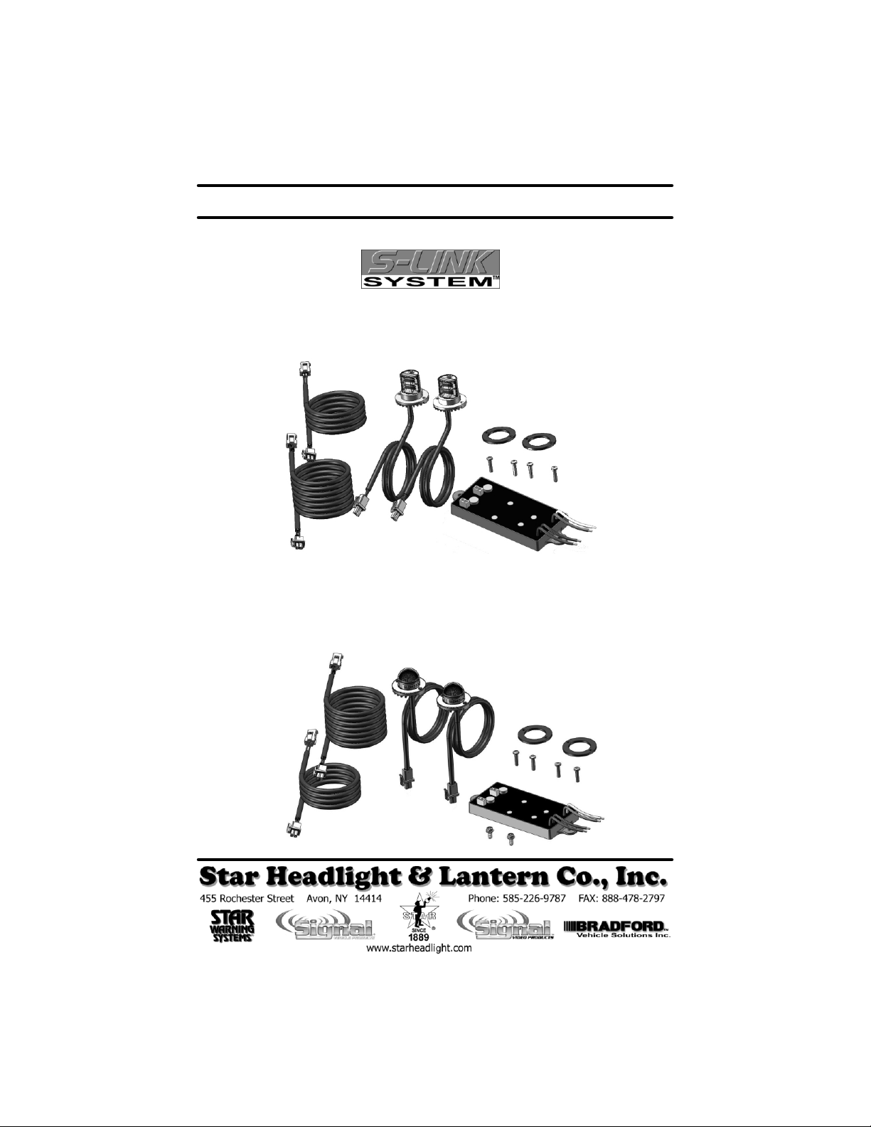
Hideaway Undercover Remote Flashing LED Kits
LDK302 and LDK304
Unidirectional Head LED Kits
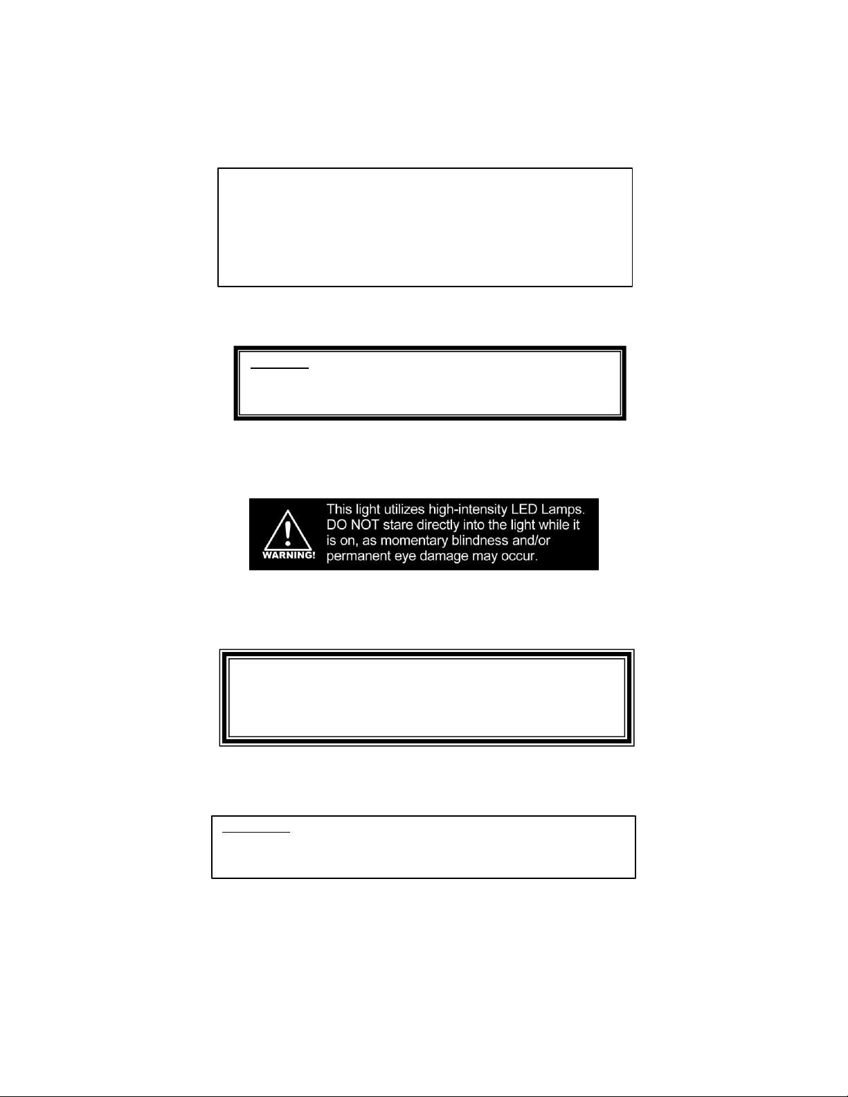
LDK312 and LDK314
Spherical Head LED Kits
PLIT423 REV. C 2/9/10
Page 2
Due to continuous product improvements, we must reserve the right to change any
NOTICE
specifications and information, contained in this manual at any time without notice.
Star Headlight & Lantern Co., Inc. makes no warranty of any kind with regard to this
manual, including, but not limited to, the implied warranties of merchantability and
fitness for a particular purpose. Star Headlight & Lantern Co., Inc. shall not be liable
for errors contained herein or for incidental or consequential damages in connection
with the furnishing, performance, or use of this manual.
WARNING: This device may be regulated by Federal, State, and/
or Local ordinances. These devices may be used
ONLY on approved vehicles. It is the sole
responsibility of the user to ensure compliance.
IMPORTANT: Please read all of the following instructions before
installing your new light. Failure to follow these
safety precautions may result in damage to your light
or vehicle and may result in serious injury or death to
you and your passengers.
Please Note: These instructions are provided as a general guideline only. Some
vehicles may require special mounting, wiring, and/or weather -sealing. This is the
sole responsibility of the installer. Star Headlight & Lantern Co., Inc. assumes no
responsibility for the integrity of the installation for this or any of its products.
-i-
Page 3

Parts
Contents:
LDK302 LDK304 LDK312 LDK314 Part Number Description
1 2 1 2 LDF300 2-Head Flasher Unit
2 4 2 4 P30053 -46 3/8” Philips Hex Screw (for Flasher)
2 4 0 0 LDH300C -* Unidirectional LED Head (*=color)
0 0 2 4 LDH310C -* Spherical LED Head (*=color)
2 4 2 4 P30052 -46 5/8” Philips Head Screw (for Heads)
2 4 2 4 P30047 -118 Gasket for LED Head
1 2 1 2 SWH -L4 4’ Cable with Connectors
1 2 1 2 SWH -L8 8’ Cable with Connectors
Optional Parts:
Part Number Description
LSF300-* Colored Filter for Unidirectional LED Head (*=color)
LSF310-* Colored Filter for Spherical LED Head (*=color)
SWH -L4 4' Extension Cable for LED Heads
SWH -L8 8' Extension Cable for LED Heads
SWH -L15 15' Extension Cable for LED Heads
SWH -L20 20' Extension Cable for LED Heads
SWH -L25 25' Extension Cable for LED Heads
SWH -L30 30' Extension Cable for LED Heads
SWH -L35 35' Extension Cable for LED Heads
Installation Notes
Proper installation of the unit is essential for years of safe, reliable operation. Please read
all instruction before installing the unit. Failure to follow these instructions can cause
serious damage to the unit or vehicle and may void warranties.
• The installer must have a firm knowledge of basic electricity, vehicle electrical systems,
and emergency equipment.
• If you need to drill any holes when installing this product, please take care to check that
BOTH SIDES of your drilling surface are clear from obstructions, to ensure that you do
not damage your vehicle and or pre -existing wiring.
• Controls should be placed within convenient reach of the driver.
Before beginning the installation:
• Determine where the heads are to be mounted.
• Determine where you will mount the switch.
• Determine if you will be synchronizing your LDF300 flasher with any other LDF300 flashers or
any other synchronizable products.
• Verify that you have a clear path to run your wires between the heads, flasher unit(s), switch,
and any other lights that the flasher will be synchronized with.
Keep These Instructions - Keep these instructions in the vehicle or other safe place for
future reference. Advise the vehicle operator of the location.
-1-
Page 4

Installation
• Each flasher can control 2 LED heads
• The LED light heads must be installed inside an existing light assembly on the vehicle.
• Unidirectional LED light heads must be vertical to ensure proper light distribution.
• Spherical LED light heads can be installed in any direction.
• Unidirectional LED light heads should only be installed in a 1” hole on a top or bottom
surface that allows the base of the head to be horizontal. Both the Unidirectional and
Spherical LED light heads should have 3” diameter total clearance inside the housing (allows
1” clearance on all sides of the head).
1. Establish a location for each flasher unit that is close to the LED heads it will operate The
location should have limited exposure to the environment (e.g. trunk, engine compartment, cab,
etc.). Use the enclosed hex head screw (P30053-46) to attach the flasher to the vehicle.
2. Determine a path for the Power and Ground wires from each unit (as well as the WHITE sync
wires if installing and synchronizing multiple flashers or other synchronizable heads).
3. Remove the headlight or taillight assembly according to the vehicle manufacturer’s instructions.
4. Find a location on each light
assembly that will
accommodate the light head,
as well as not interfere with
other components.
Remember that Unidirectional LED heads must be installed on a horizontal surface.
5. Using a #40 bit, drill your holes according to the diagrams below. For the Unidirectional
LED light heads , take care to drill the screw holes so that when installed, the heads will
be directed out of the corners at a 45º angle to the vehicle (see diagram below).
6. Place a gasket over each head and install the heads using the 5/8” Philips head screws
included.
7. Re-assemble the light housings on your vehicle.
WARNING!! The heat output of the LED
head can melt plastic if it is not installed
with adequate space around the unit. A
minimum of 1” clearance is recommended.
-2-
Page 5

Wiring
When wiring your LED Kit(s) (and compatible) lights, YOU MUST take the
• The LED modules and the radio (or other sources of EMI) should be kept as far away
• Separate the radio wires and the LED wires:
• Any excess wires should be cut short.
• The Ground wire, Power wire, Synchronization wire , and High/Low wire (if used)
• Do not ground each unit independently to the chassis. Run the ground for each unit
BEFORE installing your lights and running your wires, please review the
diagram below showing an example of how the wires should be run.
following precautions to eliminate Electromagnetic Interference (EMI).
from each other as possible.
© The radio antenna wire should make a right angle from the back of the radio and
run down one side of the vehicle.
© The LED wires should make a right angle out of the back of the switchbox and
exit in the opposite direction of the antenna wire and/or radio power wires.
should be bound tightly together as they run from light to light, through your
switchbox, and finally to the battery.
as shown below in a “bus” like structure, to the negative terminal on the battery.
RADIO POWER WIRESANTENNA LEAD
SWITCHBOX
RADIO
DLX3DLX3
LDH300C or
LDH310C
Heads
LDF300
POWER
GROUND
1. Connect the Black wire to the negative terminal of
your battery.
2. Connect the Red wire to your switch that supplies
+12-24 VDC.
SYNC
Optional
Compatible
360° Lights
POWER & SYNC WIRES
360 360
CORNERLIGHTSMODE1 2 3 GRILL LIGHTSHEADLIGHTFLASHER
TAKE
DOWN
BATTERY
Black: Battery Negative
Red: +12-24 VDC
White: Synchronization
Green: Pattern Select
LDF300
DLX3
DLX3
3. If you are synchronizing two or more flasher units, run the White wires along with the
Red and Black wires to each unit (as shown above), but DO NOT CONNECT THE
WHITE WIRES UNTIL PROGRAMMING HAS BEEN COMPLETED (see next two
pages). Note: The total distance between the two farthest units should be no more than
40 feet. If you are NOT synchronizing units, cut this wire short and tape it off.
4. The Green is used for Pattern Programming (see next page).
-3-
Page 6

Pattern Programming
The LDF300 flasher unit has twenty different
Flash Patterns to select from.
(see chart to right)
These patterns include:
• 11 different alternating patterns (the
two heads flash back and forth)
• 4 different simultaneous patterns in
each of 2 phases (the two heads flash
at the same time)
• A Cycle All pattern (continuously cycles
through patterns 1-19)
Programming Procedure:
1. If you are NOT synchronizing your
LDF300 with another LDF300 or
approved light, tape the WHITE wire off
so that it does not come into contact with
anything.
2. The GREEN wire is used to program
the desired flash pattern. After the
BLACK and RED wires are
connected (see previous page), you
may set the flash pattern. The LDF300
flasher is programmed at the factory for
Pattern 6 (Pattern Type F – Alternating
Quadflash). To change the pattern,
proceed below:
• Touch and hold the green wire to
ground until the light blinks once
(approximately 3 seconds), then
release it. This will reset the
light to Pattern 1 (Pattern Type K
– Alternating Flicker).
• Touch the green wire to ground
for approximately 1 second and
release it to cycle through
Patterns 1-20 shown to the right.
After Pattern 20, the light will
cycle back to Pattern 1.
Type
Pattern
Pattern #
1 K
2 L
3 M
4 N
5 O
6 F
7 G
8 H
9 I
10 J
11 P
12 K
13 K
14 I
15 I
16 G
17 G
18 F
19 F
20 NONE
Pattern Description CPS
Alternating Flicker †
Alternating Fast Doubleflash
Alternating Tripleflash
Alternating PSU Flicker
Alternating PSU Random
Alternating Quadflash ††
Alt. Quadflash w/Post-Pop
Alternating Singleflash
Alternating Doubleflash
Alternating Variable
Alternating Quintflash †††
Simultaneous Flicker (Phase 1)
Simultaneous Flicker (Phase 2)
Sim. Doubleflash (Phase 1)
Sim. Doubleflash (Phase 2)
Simultaneous Quadflash
w/Post-Pop (Phase 1) ††††
Simultaneous Quadflash
w/Post-Pop (Phase 2)
Simultaneous Quadflash (Phase 1)
Simultaneous Quadflash (Phase 2)
Cycle All
† = Programming Shortcuts 1, 2, 3, and 4 (see table below)
2 Complete flash cycles
Head 1
Phase 1
(ON) (OFF)
Cycle 1
Phase 2
TIME
Phase 1
Cycle 2
Phase 2
Head 2
2 Complete flash cycles
Head 1
Head 2
1.0
3.3
2.5
0.7
0.6
1.0
1.0
1.0
1.0
0.3
1.2
1.0
1.0
1.0
1.0
1.0
1.0
1.0
1.0
N/A
Touch the Green Wire to Ground For: Unit Blinks Jumps To
Programming Shortcuts
3 seconds 1 time Pattern 1
6 seconds 2 times Pattern 6
9 seconds 3 times Pattern 11
12 seconds 4 times Pattern 16
-4-
Page 7

3. Once you have found the desired pattern, tape off or place a wirenut over the end of the
green wire to prevent it from coming into contact with ground again. The light will
“remember” the pattern when switched off and that pattern will be displayed the next time
the light is switched on.
If you ARE NOT synchronizing two units, you are finished programming.
Synchronizing Multiple Lights
You can synchronize two flashers and/or other lights that use the system.
If you will be synchronizing two or more units together, leave the white wires
disconnected until programming for each has been completed . Connect the
white wires from the units together ONLY AFTER PROGRAMMING them all
for the same Pattern Type (Phase MAY differ).
If you will be synchronizing your LDF300 flasher with another LDF300 flasher, or synchronizing it
with any of our other products (i.e. DLX units, 9016LED minibars, and 255HTCL
beacons), please note the following:
• All units that are to be synchronized MUST have the same Pattern Type.
• To check pattern compatibility with other
“synchronizable” products, review the
Pattern List for each product, noting the
Pattern Type. Certain patterns are
compatible with some lights, but not
compatible with others.
• Although the programmable Flash
Patterns can vary in each of our different
lights, Flash Patterns 6-10 (Pattern Types
F, G, H, I, & J) are the patterns fully
compatible with ALL of our other
“synchronizable” products.
1. Determine whether you want the two heads attached to your LDF300 flasher unit to flash
PATTERN COMPATIBILITY
LDF300: All Patterns
DLX Series: Pattern Types F, G, H, I, J
9016LED: Pattern Types
F, G, H, I, J, K, L, M, N, O
255HTCL: Pattern Types F, G, H, I, J
alternately or simultaneously (Review the diagram on the bottom of the previous page for
examples of Alternating and Simultaneous flashing).
2. Review the Pattern List for each product you will be synchronizing, noting the Pattern Type
for each product.
3. Select a Pattern Type that is compatible with all of the flasher units/lights you will be
synchronizing.
4. Program each light according to the instructions enclosed with each. For lights that have
patterns with a Phase: All lights programmed for the same Phase will flash ON and OFF at
the same time (flash simultaneously). Lights that are programmed for different phases will
flash opposite one another (alternate).
5. After you have the correct patterns programmed in for ALL of the lights you wish to
synchronize, turn all of the lights off and connect the white wires from all units
together.
6. Power all of the lights up at the exact same time to verify they are flashing in the
desired pattern. Power MUST be applied to all synchronized lights
simultaneously. Excessive switch bounce or attempting to power the units up
independently will result in erratic operation.
-5-
Page 8

The heads in these kits use state -of-the-art Light Emitting Diode (LED) technology. These warning
lights are comprised of ultra-high intensity LEDs that are controlled by a solid state flasher unit to
efficiently produce light output with lifetimes up to 100,000 hours. Under normal circumstances,
you will not need to replace any LEDs in this light. If any of the LED's in your light do fail, please
contact Star Headlight for arrangements to have them repaired. The flasher unit and heads
CANNOT be serviced in the field and any attempt to do so will void the warranty.
LED FIVE YEAR LIMITED WARRANTY
The manufacturer warrants this LED light against factory defects in material and
workmanship for five years after the date of purchase. The owner will be responsible for
returning to the Service Center any defective item(s) with the transportation costs
prepaid. The manufacturer will, without charge, repair or replace at its option,
products, or part(s), which its inspection determines to be defective. Repaired or
replacement item(s) will be returned to the purchaser with transportation costs prepaid
from the service point. A copy of the purchaser's receipt must be returned with the
defective item(s) in order to qualify for the warranty coverage. Exclusions from this
warranty include, but are not limited to, domes, and/or the finish. This warranty shall not
apply to any light, which has been altered, such that in the manufacturer's judgment,
the performance or reliability has been affected, or if any damage has resulted from
abnormal use or service.
There are no warranties expressed or implied (including any warranty of merchantability
or fitness), which extend this warranty period. The loss of use of the product, loss of time,
inconvenience, commercial loss or consequential damages, including costs of any
labor, are not covered. The manufacturer reserves the right to change the design of
the product without assuming any obligation to modify any product previously
manufactured.
This warranty gives you specific legal rights. You might also have additional rights that
may vary from state to state. Some states do not allow limitations on how long an
implied warranty lasts. Some states do not allow the exclusion or limitation of incidental
or consequential damages. Therefore, the above limitation(s) or exclusion(s) may not
apply to you.
If you have any questions concerning this or any other Star product,
please contact our Customer Service Department at (585) 226-9787.
If a product must be returned for any reason,
please contact our Customer Service Department to obtain a
Returned Goods Authorization number (RGA #) before you ship the product to Star.
Please write the RGA # clearly on the package near the mailing label.
-6-
 Loading...