

Page 1
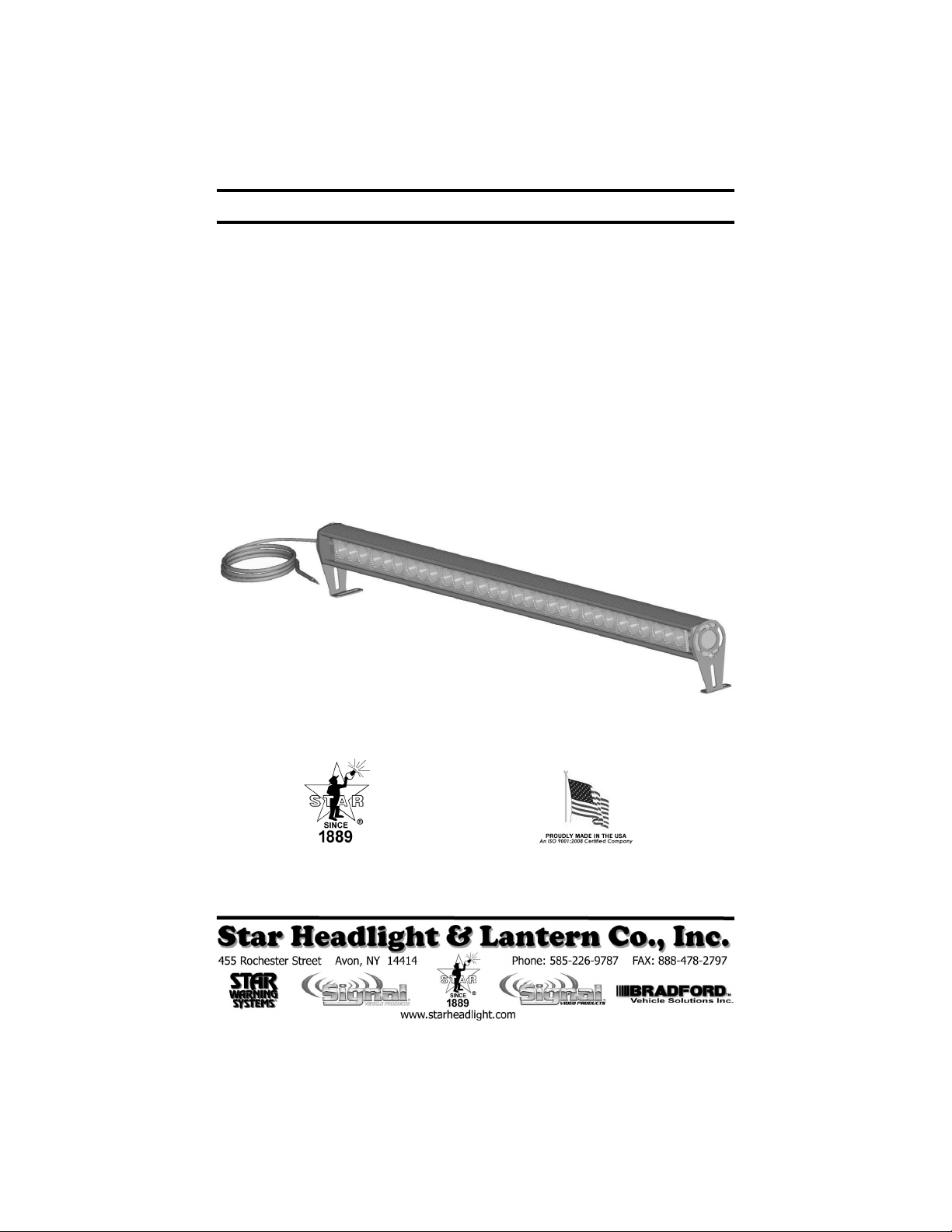
INSTALLATION AND INSTRUCTION MANUAL
DL15
DL15-
DL15DL15
LED TRAFFIC DIRECTOR
WARNING STICK
-30W
30W
--
30W30W
and
PLITSTR77 REV. C 9/12/11
Page 2
IMPORTANT: Please read all of the following instructions before installing your new LED
Traffic Director and Warning Stick.
CAUTION: Please be sure to check that your light is properly fused. Testing the light
before this fuse is properly installed will void the warranty on the light.
WARNING!!!! Care should be taken when positioning this warning light so that the light
and/or cord does not interfere with the proper operation of any of the
airbags! Failure to heed this warning may result in serious or fatal injury.
It is the sole responsibility of the owner to ensure the warning light is
secure. Check your light every time you enter the vehicle to ensure that
it is mounted securely. Star Headlight and Lantern Co. assumes no
responsibility for the secure mounting of this light.
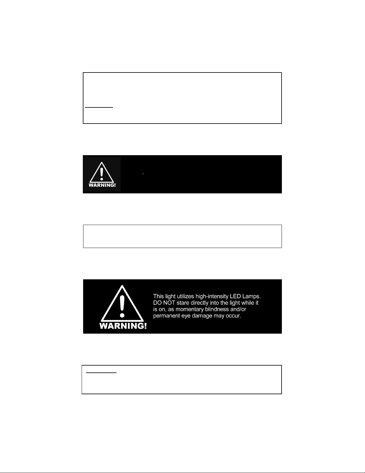
These lights use state-of-the-art Light Emitting Diode (LED) technology. This warning
light is comprised of ultra-high intensity LEDs that are operated by a micro-controller to
efficiently produce light output with lifetimes up to 100,000 hours.
Please Note: These instructions are provided as a general guideline only. Some
vehicles may require special mounting, wiring, and/or weather-sealing. This is the
sole responsibility of the installer. Star Headlight & Lantern Co., Inc. assumes no
responsibility for the integrity of the installation for this or any of its products.
-i-
Page 3

Important
: This product is used to direct traffic. Improper use
may result in vehicular collision, personal injury and/or death. Star
Headlight & Lantern Co., Inc., and its subsidiaries shall not be held
responsible for damages directly or indirectly caused by improper
use of this product. Always carefully consider the effect on traffic
that the selected light pattern will have before engaging the lights.
Table of Contents
Safety Warnings i
Preparation 1
Stick Mounting 2-3
Electrical Connections 4
SP1515-TDC and
User Supplied Switches 4
Pattern Selection 5-6
Operation 7
TD77-2 8-12
Cover Removal
Jumper Setting
Connections
Operation
Pattern Display LEDs
TDC850 12-15
Cover Removal
Jumper Setting
Connections
Operation
Stick Adjustment 16
Parts 16
Troubleshooting 16
Warranty 17
8
9
10
11
12
12
13-14
14
15
Due to continuous product improvements, we must reserve the right to change any specifications and
information, contained in this manual at any time without notice. Star Headlight & Lantern Co., Inc. makes no
warranty of any kind with regard to this manual, including, but not limited to, the implied warranties of
merchantability and fitness for a particular purpose. Star Headlight & Lantern Co., Inc. shall not be liable for
errors contained herein or for incidental or consequential damages in connection with the furnishing,
performance, or use of this manual.
-ii-
NOTICE
Page 4
Preparation
Before beginning the installation:
• Determine where the Traffic Director is to be mounted.
• Check to see that there are no obstructions hindering the visibility of
your traffic director.
• Select a location to mount your controller (purchased separately or
user supplied). The controller must be located in a dry location out of
direct sunlight, free of dirt and dust. Under the vehicle's instrument
panel is usually the best choice.
• Once you have selected these locations, determine the path that
your cable connecting the controller to the Traffic Director will take.
The cable should exit the driver’s side of the rear facing Traffic
Director.
Be sure the cable attached to your Traffic Director is long enough for
proper installation. If it is too short, you will need to order a Traffic
Director with the correct length cable pre-installed. The standard length
for the cables is 15'. Star does not recommend “splicing in”
additional cable when the supplied cable is too short. Traffic
Directors with longer cables are available upon request.
-1-
Page 5
Mounting
It is the owners sole responsibility to ensure that the mount is
secure and will not come loose while the vehicle is in motion.
1. Select a location for the light to be mounted. Take into consideration viewing angles,
mounting holes, and where the cable will run when selecting a location. The cable
should exit the driver’s side of the rear-facing stick.
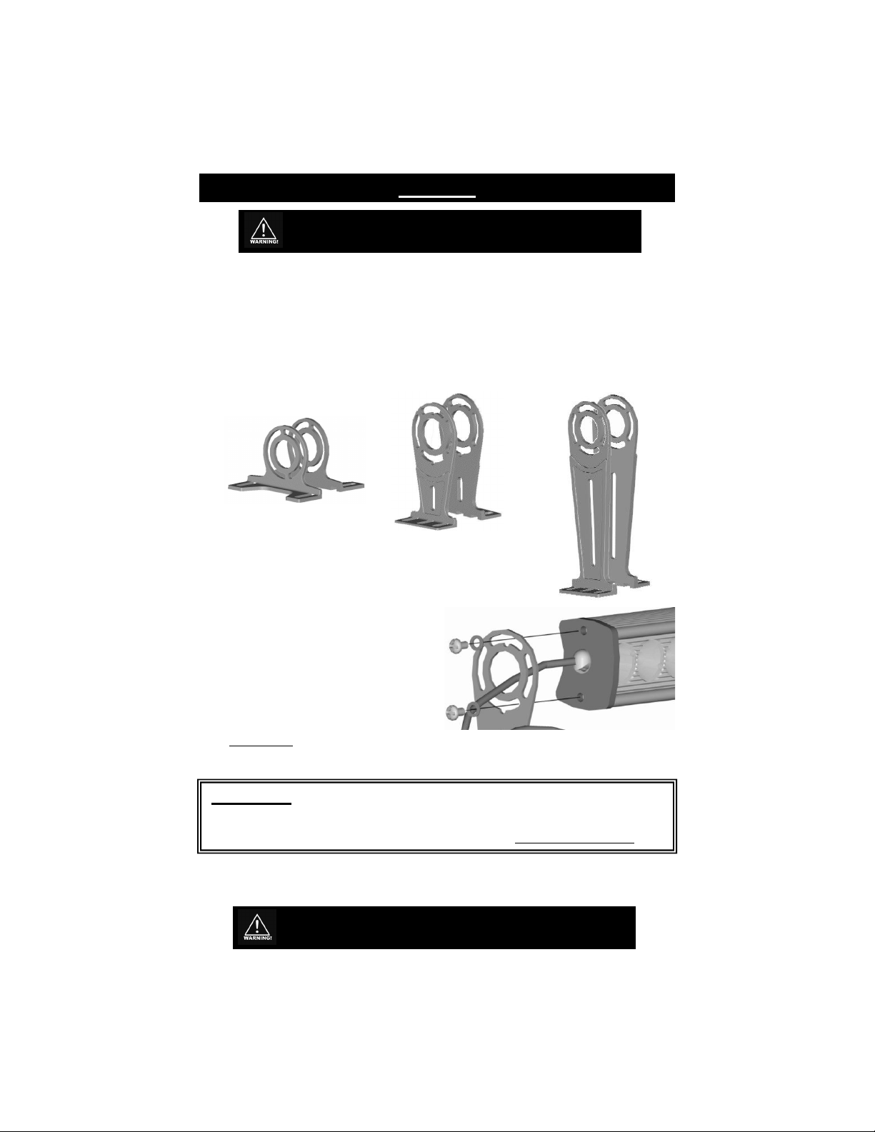
2. Once you have selected the location to mount your light(s), determine which leg size
suits your application best. There are three different size legs included with the
DL15-30W Series lights: Short Leg Brackets (DL15-BKT-S), Medium Leg Brackets
(DL15-BKT-M), and Tall Leg Brackets (DL15-BKT-T).
DL15-BKT-M
DL15-BKT-S
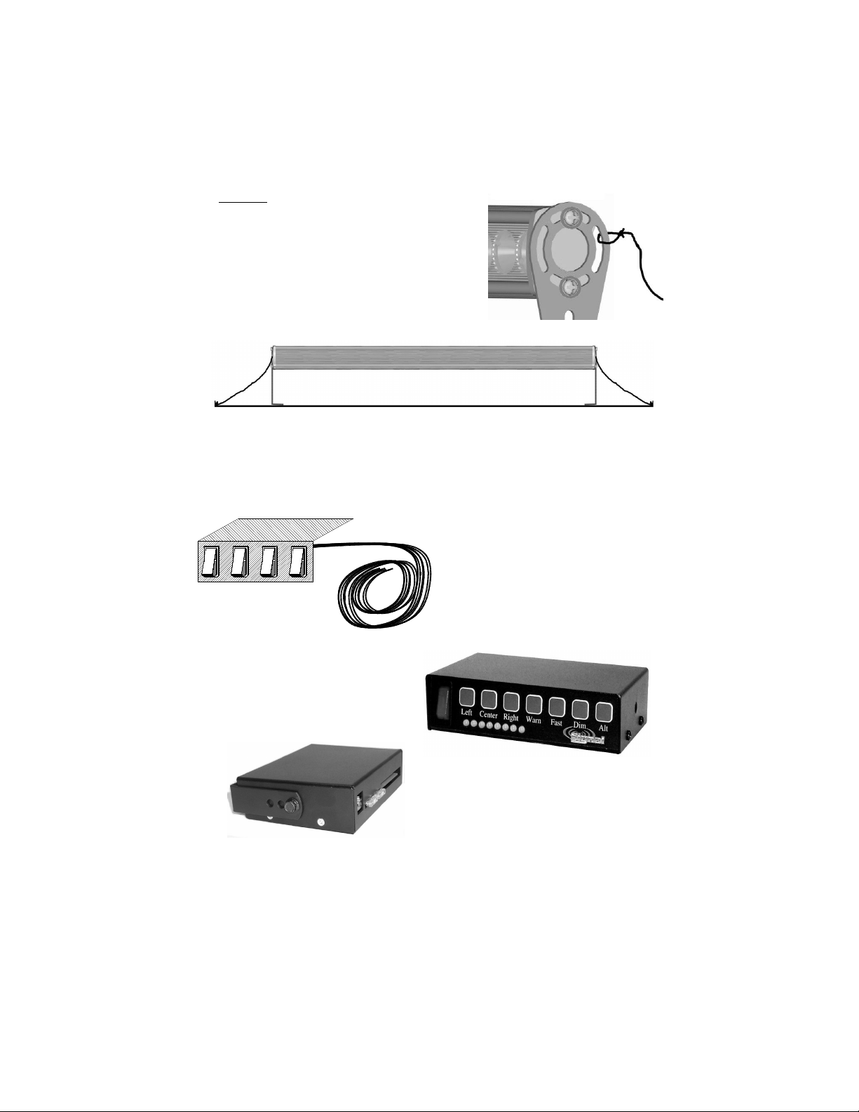
3. Remove the two screws in one end of the light and use
them, with two of the enclosed washers, to attach one of
the mounting legs, routing the cord through the center
of the leg (shown to the right). When
installing the legs, take into account
which direction the light will face, where
the legs will mount, and which end the
cord will exit from. Select the appropriate
slots in the leg to fasten the screws
through. Repeat this step for the other
side with the other leg.
Please note: The cable needs to run through the center of the mounting bracket
as pictured above and exit the driver’s side of the rear facing DL15-30W.
DL15-BKT-T
CAUTION!!:
you are installing the legs, please take extreme care to ensure that the endcap is
replaced in the exact same orientation it was originally in. If it is not replaced
properly the weatherproof seal may be broken and the warranty will be voided.
4. Mount your light in the desired location. Use appropriate fasteners (not supplied) to secure
the legs to your mounting surface.
In the event the endcap should become detached from the lightstick as
It is the owners sole responsibility to ensure that the mount is
secure and will not come loose while the vehicle is in motion.
-2-
Page 6
(Mounting CONT’D)
5. You must then install the enclosed tether cords, which
will help secure the light in case of impact. Attach one
tether to each leg as pictured to the right. Attach the
other end of each tether to a secure mounting point.
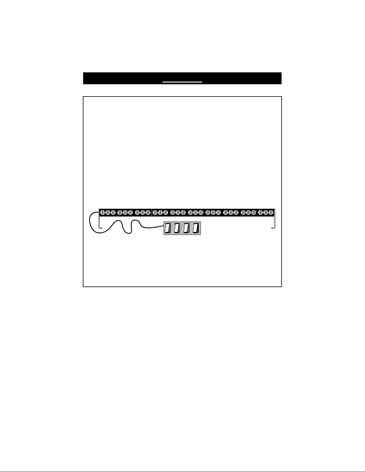
6. Each tether should be secured in separate locations
within 10" outside the legs of the light. Make sure there
is virtually no slack in the tethers. (See diagram below.)
CAUTION: Be sure the mount and/or fasteners used
are sufficient to support the weight of your light in
case of an accident.
7. Once the DL15-30W is mounted, you should select a location for your switch panel that is
easily accessible to the driver. The switches must be located in a dry location out of direct
sunlight, free from dirt and dust. Under the vehicle's instrument panel is usually the best
choice. You may use your own switches, or you may order the SP1515-TDC, TD77-2, or the
TDC850 (for use with SVP sirens that have built-in traffic director controls). If you are using
your own switches, you will need a 4-switch switch panel, with 4 SPST On/Off switches.
SP1515-TDC
(Optional Switch Panel)
(Optional Controller w/LED Display)
TD77-2
TDC850
(Optional Controller for use w/SVP sirens)
8. Mount your switch panel using appropriate fasteners (not supplied).
9. Once the light and switch panel are secured, route your cable to your switch such that it does
not interfere with the vision of the driver or the operation of the steering wheel, gear shifter,
and/or any airbags.
-3-
Page 7

Electrical Connections
The DL15-30W comes with a 15' six-conductor cable. The six wires perform the following
functions:
You can control your light using your own switches, with the optional SP1515-TDC (see
below), or with the optional TD77-2 (see pages 8-12).
If you will be using the OPTIONAL TD77-2 to control your light, please skip to the
corresponding section on page 8.
If you are using your own switches, you will need a 4-switch switch panel, with 4 SPST On/Off
switches.
1. Connect the black wire to a good chassis ground.
2. The red, yellow, purple, and green wires will be connected to your switch panel. Please
3. After the black wire is grounded, and the red, yellow, purple, and green wires are
Black Wire (18AWG) - Ground
Red Wire (18AWG) - Power (operating voltage 10-16VDC)
Yellow Wire (22AWG) - Left Arrow (+12VDC)
Purple Wire (22AWG) - Center Out(+12VDC)
Green Wire (22AWG) - Right Arrow(+12VDC)
White Wire (22AWG) - Pattern Change (Touch and release to ground)
Connecting the Optional SP1515-TDC
(you may also use your own standard On/Off switches)
review the diagram below for proper wiring, using four SPST switches. The SP1515TDC (available from Star) utilizes four lighted switches. If you are using your own “non-
lighted” switches, there will be no #3 terminal on each switch, and the switch panel itself
will not need to be grounded.
connected to your switch panel, the light is ready for operation and pattern selection.
STAR MODEL #SP1515-TDC
OPTIONAL LIGHTED SWITCH PANEL
(REAR VIEW)
R
SW4
GREEN
GREEN
C-O
3
2
1
3
2
1
SW3 SW2
PURPLE
P
U
R
L
3
2
1
RED
YELLOW
Y
E
L
L
O
P
L
E
W
PWR
3
2
1
SW1
R
E
D
BLACK
FUSED RED LEAD
10 AMP
FUSE
(Not used for non-lighted switches)
GOOD
CHASSIS
+12 VDC
GROUND
W
CONNECT TO
BLACK
H
I
T
E
Touch And Release to Ground
to Select Pattern, Then Cap Off
Please note: For non-lighted switches, there will be no Terminal #3 on each switch
and there is no ground wire (black wire) on the switch panel.
-4-
Page 8

Optional Pattern Selection
Pattern Selection for the DL15-30W when Using the SP1515-TDC
After your light and switch panel have been installed, you have the option of changing either
or both of the following:
When the light is initially activated by turning the PWR switch on, it will display a “Warn
Pattern”. The light has been pre-programmed at the factory to display Pattern 1 (Alternating
Slow Singleflash). Review the list below and decide if you wish to change the default
Warning Pattern.
Pattern Description
1 Alternating Slow Single (1-5 vs. 6-10) (default) †
2 Alternating Fast Single (1-5 vs. 6-10)
3 Alternating Triple (1-5 vs. 6-10)
4 Alternating Quad (1-5 vs. 6-10)
5 Alternating Quint (1-5 vs. 6-10)
6 Alternating Triple (1,26,7,8 vs. 3,4,5,9,10)
7 Alternating Quint (1,26,7,8 vs. 3,4,5,9,10)
8 Simultaneous Slow Single (All modules) †
9 Simultaneous Fast Single (All modules)
10 Simultaneous Triple (All modules)
11 Simultaneous Quad (All modules)
12 Simultaneous Quint (All modules)
13 Simultaneous Triple (All modules)
14 Simultaneous Quint (All modules)
15 In/Out Single (1,2,9,10 vs. 3-8)
16 In/Out Triple (1,2,9,10 vs. 3-8)
17 In/Out Quint (1,2,9,10 vs. 3-8)
18 In/Out Single (1,2,3,8,9,10 vs. 4-7)
19 In/Out Triple (1,2,3,8,9,10 vs. 4-7)
20 In/Out Quint (1,2,3,8,9,10 vs. 4-7)
21 1-5 Steady; 6-10 Single Flash †
22 1-5 Steady; 6-10 Slow Single Flash †
23 6-10 Steady; 1-5 Single Flash †
24 6-10 Steady; 1-5 Slow Single Flash †
25 Sequential Back and Forth
26 Sequential In/Out
27 Burst All w/ Alternating Burst
28 Alternating Burst w/ Double then Quint
29 Simultaneous Burst /w Double then Quint
30 Hyper Random
31 Demo Mode (two sequences of each pattern, except 20-23)
x OFF
† = California Title 13, SAEJ595, and SAEJ1318 Approved)
A. The default Warning Pattern
B. The style of your Traffic Directing Patterns
(or User Supplied Switches)
Optional Warning Patterns
Arrays for the DL15-30W
Array #1 Array #2 Array #3 Array #4 Array #5 Array # 6 Array #7 Ar ray #8 Array #9 Array # 10
{
{
{
{
{
{
{
{{{
-5-
Page 9

B
L
A
C
K
=
G
r
o
u
n
d
(Optional Pattern Selection CONT’D)
If you do not wish to change the Warning Pattern, skip to the Optional Traffic Directing
Pattern Styles section below. To change the default Warning Pattern, proceed below.
PWR C-OL R
1. To select the Warning Pattern,
activate your light by turning on the
PWR switch. When activated the
stick should be in Pattern 1
(Alternating Slow Single (1-5 vs. 6-10))
.
(Switch panel shown with PWR switch in “ON”
position and other switches in “OFF” position.)
2. Touch and release the white wire to ground to scroll
through the patterns listed on the previous page.
3. Once you have found
the desired Warning
P
GREEN = Right
U
Y
R
E
P
L
E
=
C
-
O
Pattern, you can turn
the light off. The light will “remember” the last selected pattern
R
E
D
=
P
L
L
O
W
W
=
R
L
e
f
t
W
H
I
T
E
=
P
a
t
t
e
r
n
S
e
l
e
when switched off and that pattern will be displayed the next time the
light is switched on.
Optional Traffic Directing Pattern Styles
After the PWR switch is activated and any of the Traffic Directing Patterns (L, C-O, R) are
activated, the light will display the corresponding pattern (Left, Center-Out, or Right).. There
are several different “styles” is which these patterns can be displayed. The light has been
pre-programmed at the factory to display Style 1 (10 Head Normal) when any of the Traffic
Directing Patterns are activated. Review the list below and decide if you wish to change the
default Traffic Directing Pattern Style.
Style Description
1 10 Head Normal (default)
2 10 Head Dual Light
3 10 Head Normal with End Blink
4 10 Head Dual Light with End Blink
5 6 Head Normal w/Warn
6 6 Head Dual Light w/Warn
Normal - Starts with one light and consecutively adds lights to the pattern until they are all
Dual Light - Only two lights will be illuminated the same time. The two lights will "roll" or “travel”
End Blink - Same as the Normal or Dual Light pattern with the exception that the last light will double
Warn - This option only uses the center 6 arrays (3 LED’s in each array) for traffic directing. The
illuminated
in the direction of the selected pattern
blink.
two arrays on each end will flash back and forth in a warning pattern.
1. If you wish to change the Traffic Directing Pattern Style, turn the PWR switch on and
activate any one of the other switches (L, C-O, or R). This will place the bar into Traffic
Directing Mode.
2. Touch and release the white wire to ground to scroll through the six different display
styles listed above.
3. Once you have found the desired style, switch the light off and tape or place a wirenut
over the end of the white wire to prevent it from coming into contact with the ground again.
4. OPTIONAL: If you wish to utilize your own remote pattern select switch, you may
connect the white wire to ground through a momentary on/off switch (user supplied).
NOTE: Adding this switch will void the California Title 13 approval.
c
t
-6-
Page 10

Operation
SP1515-TDC or Standard Switch Operation
Important
vehicular collision, personal injury and/or death. Star Headlight & Lantern Co.,
Inc., and its subsidiaries shall not be held responsible for damages directly or
indirectly caused by improper use of this product. Always carefully consider the
effect on traffic that the selected light pattern will have before engaging the lights.
1. Operation of the DL15-30W is straightforward. Four switches are used to control the
various functions : Warn, Left, Center Out, and Right Patterns.
2. The unit is activated by switching the PWR switch ON (attached to red wire). The
light will go into Warning mode with the pattern you have pre-selected (see the
Pattern Selection section on the following page).
3. Select a Traffic Directing pattern by switching the appropriate switch ON.
L - Left Pattern
C-O - Center Out Pattern
R - Right Pattern
Please note: The PWR switch must also be on for the Traffic Directing
4. If more than one of the Traffic Directing switches (R, C-O, L) is activated, the stick
will default to the Center-Out mode for safety reasons.
5. When using the Traffic Director, always be sure that the pattern selected is
appropriate for the present hazard condition. The potential danger in displaying
an inappropriate pattern cannot be overstated.
: This product is used to direct traffic. Improper use may result in
PWR L
Patterns to activate.
C-O R
Once your Traffic Director is installed, please test all the patterns, options, and
alternate versions to familiarize yourself with the various patterns and the
operation of the controller.
-7-
Page 11

Optional TD77-2 Controller
TD77-2
(Optional Controller w/LED Display)
You may choose to control your DL15-30W with the optional TD77-2 controller (ordered
separately). This controller has a number of benefits over the SP1515-TDC or any other
standard switches:
TD77-2 Control Box Cover Removal
• The TD77-2 provides an LED display that shows which mode
the light stick is operating in (Off, Left, Center, Right, or Warn).
• The TD77-2 allows you to change your Warning Pattern and
the style of your Traffic Directing Patterns. (Please note that
this feature must be disabled if you need to meet
California Title 13 specifications.)
• The Pattern Control Switches on the TD77-2 are all backlit
anytime the unit is powered on.
Prior to connecting the TD77-2 to your DL15-30W, you must set an internal
jumper. YOUR TD77-2 WILL NOT CONTROL THE DL15-30W
LIGHTSTICK PROPERLY WITHOUT FIRST SETTING THIS JUMPER.
1. Remove the four recessed
Philip head screws (two on
each side of the control box).
2. Remove the top cover by
sliding it towards the back of
the unit.
-8-
Page 12

(Optional TD77-2 Controller CONT’D)
TD77-2 Jumper Setting for use with the DL15-30W
1. Locate the “Option” jumper location near the center of the board. (See diagram below).
TD77-2 Controller (DL15-30W Mode)
Move Jumper
from 1st pair
To use the TD77-2 with the DL15-30W, YOU
MUST remove the jumper on the 1st pair of pins
!
and turn it sideways over the bottom row of the
1st and 2nd pair of pins.
2. The first set of pins (see above) will have a jumper on them. Remove this jumper from
the first pair of pins and place it over the bottom pins of the first and second pair of pins
as pictured above.
3. Replace the cover of the TD77-2, taking care not to over tighten the screws.
-9-
Page 13

(Optional TD77-2 Controller CONT’D)
Connection of the DL15-30W wires to the TD77-2
+12 VDC
EMPTY
EMPTY
EMPTY
EMPTY
YELLOW
GREEN
VIOLET
WHITE
BLACK
GROUND
RED
1 2 3 4 5 6 7 8 9 10 11 12
CONTROL WIRES
GROUND TO
LIGHTSTICK
OUTPUT POWER
BATTERY +
BATTERY -
TO LIGHTSTICK (+12VDC)
1. The TD77-2 control box comes with a removable green terminal block connector on the back
(part #CPSS-153). Remove the terminal block from control box and loosen all 12 terminal
screws. This will open the wire entries.
2. Make the wire connections as shown above, taking care to tighten down each screw once the
appropriate wire is inserted.
Wires From DL15-30W
Yellow: Connect the yellow wire from the lightstick to Terminal 1 of the green
Violet: Connect the violet wire from the lightstick to Terminal 2 of the green
Green: Connect the green wire from the lightstick to Terminal 3 of the green
White: Connect the white wire from the lightstick to Terminal 4 of the green
Black: Connect the black wire from the lightstick to Terminal 9 of the green
Red: Connect the red wire from the lightstick to Terminal 10 of the green connector.
Additional Connections
Ground: Using a minimum 18 AWG wire, connect this terminal to the negative of the vehicle
+12 VDC: Using a minimum 18 AWG wire, connect this terminal to a +12 VDC source, fused
3. After all of the connections are complete, insert the terminal block into the mating receptacle in
the back of the control box and tighten the two terminal block locking screws on either end of
the block to prevent it from vibrating loose.
connector. This wire activates the Left Arrow pattern on the arrow stick.
connector. This wire activates the Center Out pattern on the arrow stick.
connector. This wire activates the Right Arrow pattern on the arrow stick.
connector. This is the Pattern Select wire for the arrow stick. This wire is
optional and may be left unconnected if you do not want the user to change
your pattern options.
connector. This is the Ground wire to the arrow stick.
This wire supplies +12VDC to the arrow stick.
battery (recommended) or a good chassis ground.
with a 15A fuse at the source (battery). Star recommends the use of an ignition
switched source to avoid the possibility of draining the vehicle's battery should the
unit be accidentally left on. The lamp brightness will be somewhat diminished if a
large voltage drop exists between the vehicle's battery and the controller. It is
imperative that you supply a ground wire to the terminal marked “GROUND” ("bat -"
on the controller). You must not let the controller's case supply ground.
-10-
Page 14

(Optional TD77-2 Controller CONT’D)
TD77-2 Operation
TD77-2
(Optional Controller w/LED Display)
On/Off
Use the red rocker switch (located on the left side of the front panel of the controller) to
activate both the traffic director and the control box. When you switch it on, the stick will
automatically display the Warning Pattern (the WARN button will be illuminated in red – the
color indicating it has been activated). The LED display on the front of the controller will
mimic the output of the stick.
Changing the Traffic Directing Direction
Press the Left, Center, Right, and Warn buttons to toggle the different directional functions
of your stick. The text back light will go from green to red when the stick is operating in the
selected function. Pressing the same directional function a second time will default the stick
back to the Warn pattern.
Changing the Pattern Style
1. The ALT button on the controller will allow you to set two pattern options:
2. To select the Warning Pattern, activate your light by turning on the power switch. When
first activated, the stick should be in Pattern 1 (Alternating Slow Single (1-5 vs. 6-10)).
3. You may cycle through the different patterns, shown on the page 7, by briefly pressing
the ALT button until the lights de-activate, then releasing it. Touch and release the ALT
button until you find the desired pattern.
4. Once you have found the desired Warning Pattern, you can turn the light off. The light
will “remember” the last selected pattern when switched off and that pattern will be displayed
the next time the light is switched on.
5. After the Warning Pattern is selected, you can also select the style of the Traffic
Directing Pattern you wish to use (see list on page 7).
6. With the power switch turned back ON, activate one of the other switches (LEFT, C-O,
or RIGHT) to place the bar into Traffic Directing Mode. Once again, touch and release
the ALT button and it will scroll through the six different display styles listed in the chart
on page 7. Once you have found the desired style, switch the light off.
PLEASE NOTE: The LED display only indicates what MODE you are in (i.e. Off, Left, Center,
Right, or Warn). It will not mimic the exact pattern STYLE. Changing (scrolling through) the
STYLES will not affect the LED display.
1. The Warning Pattern
2. The style of your Traffic Directing Patterns
(See the list on page 7)
-11-
Page 15

(Optional TD77-2 Controller CONT’D)
TD77-2 Pattern Display LEDs
The four left most LEDs of the LED display on the front of the controller will mimic the
output of the stick (LEFT, RIGHT, CENTER, WARN).
• The four right amber LEDs are tied into the
outputs controlling your light bar, they will
always be lit, it is recommended you cover
these LEDs with the provided sticker. Place
the top of the sticker over the LEDs and wrap
it around the bottom of the controller, as
pictured to the right.
• For these LEDs to be accurate, you MUST have the bar wired properly with the wires
exiting on the drivers side and have a correctly functioning light stick.
• These LEDs simply show the basic pattern selected, the operation of the stick will
vary depending on the pattern selected by the user for each of the directional
functions.
Optional TD850 Controller
TDC850
(Optional Controller for use w/SVP sirens)
If you are installing the DL15-30W in a vehicle that has an SVP siren with Traffic Director
controls (i.e. LCS850, or LCS881), you may choose to control your DL15-30W with the
optional TDC850 controller (ordered separately) and the switches built into the siren.
-12-
Page 16

(Optional TDC850 Controller CONT’D)
TDC850 Option Jumpers
TDC850 Control Box Cover Removal
1. Remove the four recessed Philip head screws
(two on each side of the arrow stick control box).
2. Remove the top cover by sliding it towards the
front of the unit.
3. Locate the extra jumper location near the fuses. Also find the “Option” jumper location
near the center of the board. (See diagram below).
4. There are seven jumpers located inside the TDC850 that can control different options.
By default six of the jumpers are located on the Extra Jumper pins.
5. The 7th jumper will be in the “Phantom Mode” position over the 1st pair of jumpers.
Remove this jumper from the 1st pair of pins and place it over the bottom pins of the 2nd
and 3rd pair of pins as pictured below.
TDC850 Controller (DL15-30W Mode)
!
Phantom Mode (REMOVE
THE JUMPER FROM
THIS PAIR!!!)
Pattern Select wires
controlled by +12VDC
Extra Jumper Locations
Control Wires
switched by Ground
Remove the jumper on the 1st pair of pins
and turn it sideways over the bottom row of
!
the 2nd and 3rd pair of pins (as pictured
here) for DL15-30W Traffic Directing Mode
Move Jumper from 1st
pair across bottom pin
of 2nd and
3rd pair
-13-
Page 17

(Optional TDC850 Controller CONT’D)
6. OPTIONAL: There are two other jumpers that can be used when connecting other brand
lightsticks that have either a +12VDC activated pattern select wire or control wires that
are activated by connection to Ground. Please call our Customer Service Department at
585-226-9787 for details on this.
Arrow Stick Wiring Connections
The arrow stick control box (TDC850) comes with a removable green terminal block connector
(Power Connector). Remove the terminal block from control box.
Loosen all 12 terminal screws. This
will open the wire entries. Make the
power wire connections as shown
below, taking care to tighten down
TDC850 Arrowstick Controller
each screw once the appropriate wire
is inserted into the proper terminal.
After all the power connections are
complete, insert the terminal block
into the mating receptacle in the back
of the control box. Tighten the two
terminal block locking screws on
either end of the block to prevent it
from vibrating loose.
YELLOW
EMPTY
1 2
Black: Ground wire to the arrow stick.
Green: Activates Right Arrow on the arrow stick.
Yellow: Activates Left Arrow on the arrow stick.
Violet: Activates Center Out pattern on the arrow stick.
White: This is the Pattern Select wire for the arrow stick. It is optional and only
GREEN
BLACK
EMPTY
3
4
CONTROL WIRES
5 6
WHITE
VIOLET
(OPTIONAL)
EMPTY
7
EMPTY
8 9 10
OUTPUT POWER TO LIGHTSTICK (+12VDC)
RED
GROUND
11 12
+12 VDC
BATTERY +
BATTERY -
needs to be wired into the connector if you desire to change your
Red: This is the +12Voutput to supply power to the arrow stick.
Ground: Connect to good chassis ground, or the negative of the vehicle battery. It is
pattern options.
imperative that you supply a ground wire to the terminal marked "bat -"
+12 VDC: Connect to a fused, 12 VDC source.
on the controller; you must not let the controller's case supply ground.
Star recommends the use of an ignition switched supply to avoid the
possibility of draining the vehicle's battery should the unit be
accidentally left on. The lamp brightness will be somewhat diminished if
a large voltage drop exists between the vehicle's battery and the
controller. If voltage drop is a problem, use a relay to control a direct
battery feed. A generic relay designed for automotive lamp service
should be available from most automotive stores for this purpose. If
using a relay, don't forget to fuse the feed and signal wires at their
source, with appropriate values. For non-LED arrow sticks, use 12
AWG wire for all power and ground connections.
-14-
Page 18

(Optional TDC850 Controller CONT’D)
A telephone style cable splitter is provided with the siren. Follow the instructions
included with your siren for proper connection of the siren amp, siren/light controller,
and TDC850.
Arrow Stick Pushbutton Switches
The S1 Light Control Switch will be used to change the pattern of the lightstick. Press and
release the S1 button to change the pattern. The Warning Pattern has thirty (30) different
options/patterns you can select. The Traffic Directing Patterns (R,L,C,O) have six (6)
different options. For the complete pattern/option listing, please see page 7.
The WLRCO push button toggles the arrow output through a different pattern with each
push. (Warning, Left arrow, Right arrow, Center out arrow, and Off). The four LED arrows
to the left of the WLRCO button provide feedback as to the output of the arrow stick.
LCS880 Control Head
OFF L1 L2 L3
S1 S2 S3
HFHORNMAN YELPWAIL
LRCO
Light control button S1 will be
used to change lightstick pattern
-15-
S4 S5
RADIOPHSR
WARN
Page 19

Stick Adjustment
After the light is securely installed, loosen the adjusting
screws located on each end of your light. Tilt the light to
the desired angle and tighten the screws. Turn the light
on and check the light from the front or rear of the
vehicle, through the window (if applicable), to ensure that
it is at the most desirable angle, and that the light is not
impeded by any obstacles and/or window tinting
Parts
Adjusting Screw Washers P30072-3
Short (1-¾") Mounting Legs DL15-BKT-S
Medium (2-7/8") Mounting Legs DL15-BKT-M
Tall (5") Mounting Legs DL15-BKT-T
Kit w/1 pair each: Short, Medium, & Tall Legs DL15-SMTK
Optional 4-Switch Switch Panel SP1515-TDC
Optional Controller w/ LED Display TD77-2
Troubleshooting
The DL15 uses state-of-the-art Light Emitting Diode (LED) technology. This warning
light is comprised of ultra-high intensity LEDs that are operated by a micro-controller
to efficiently produce light output with lifetimes up to 100,000 hours. Under normal
circumstances, you will not need to replace any lights in this warning light.
Symptom
No power Power source not turned on
Odd flash
pattern
Directional
buttons
reversed
Possible Cause
Power hooked up backwards
Positive ground vehicle
Connector loose
Fuse blown
Loose connection at power source
Programmed for a random flash
pattern
Jumper not set properly
Mis-wired controller
Traffic director mounted upside
down
Is ignition switch an EXTERNAL SWITCH?
Check that Power and Ground wires are correct
Check vehicle’s owner’s manual to be sure
vehicle is NOT positive ground.
Check connector
Is an external fuse or circuit breaker used?
Check wires connected to +12VDC
Are the negative leads connected to a good
ground?
Try cycling the patterns.
See jumper setting instructions.
Swap left and right control wires.
Turn Traffic Director over or swap left and right
control wires.
Check
-16-
Page 20

LED FIVE YEAR LIMITED WARRANTY
The manufacturer warrants this LED light against factory defects in material and workmanship for
five years after the date of purchase. The owner will be responsible for returning to the Service
Center any defective item (s) with the transportation costs prepaid. The manufacturer will, without
charge, repair or replace at its option, products, or part(s), which its inspection determines to be
defective. Repaired or replacement item(s) will be returned to the purchaser with transportation
costs prepaid from the service point. A copy of the purchaser's receipt must be returned with the
defective item(s) in order to qualify for the warranty coverage. Exclusions from this warranty
include, but are not limited to, domes, and/or the finish. This warranty shall not apply to any light,
which has been altered, such that in the manufacturer's judgment, the performance or reliability
has been affected, or if any damage has resulted from abnormal use or service.
There are no warranties expressed or implied (including any warranty of merchantability or fitness),
which extend this warranty period. The loss of use of the product, loss of time, inconvenience,
commercial loss or consequential damages, including costs of any labor, are not covered. The
manufacturer reserves the right to change the design of the product without assuming any
obligation to modify any product previously manufactured.
This warranty gives you specific legal rights. You might also have additional rights that may vary
from state to state. Some states do not allow limitations on how long an implied warranty lasts.
Some states do not allow the exclusion or limitation of incidental or consequential damages.
Therefore, the above limitation(s) or exclusion(s) may not apply to you.
If you have any questions concerning this or any other product,
please contact our Customer Service Department at (585) 226-9787.
If a product must be returned for any reason, please contact our Customer Service Department to
obtain a Returned Materials Authorization number (RMA #) before you ship the product back.
Please write the RMA # clearly on the package near the mailing label.
-17-
 Loading...