


# of Total
Joules
REMOTE STROBE PACKS
Models RP242, RP244, RP906, RP310, RP320, and RP330
Owner's Manual
&
Installation Instructions
Model Heads Watts per Side Amps Special Features
RP242 2 40 16 5.5 Selectable Flash Pattern‡
RP244 4 75 20 7.0 Selectable Flash Pattern‡,
RP310D 2 24 11.25 2.1 Doubleflash
RP310Q 2 24 17.5 2.1 Quadflash
RP320 4 42 21 3.2 Doubleflash
RP330 4 60 30 6.0 Doubleflash
RP330Q 4 70 30 7.0 Quadflash
RP330S-S 4 60 30 6.0 Independent Switching Capability†
RP330S-A 4 60 30 6.0 Independent Switching Capability†
RP330SQ-A 4 70 30 7.0 Independent Switching Capability†
RP330SQ-S 4 70 30 7.0 Independent Switching Capability†
RP906 6 90 36 8.5 Selectable Flash Pattern‡
‡
User may wire pak to flash in any of the following patterns: Double, Triple, Quad, or Five Flash
* Pak contains LEDs which mimic flashing, allowing user to identify any head failures and flash patterns
† Allows user to switch one pair of heads on and off independently of the other pair (ex. front pair and rear pair)
Made In USA
Visual Diagnostics*
REV. G 3/31/04 PLITSTAR-PAK
4
NOTICE
MOUNTING 2
Table of Contents
WIRING INSTRUCTIONS 3-7
Optimax Power Plug 3
Star Pak Power Plug 4-5
Optimax Pattern Control Cable 6
Remote Heads 7
TROUBLESHOOTING 8-9
WARRANTY 10
SERVICE 10
Due to continuous product improvements, we must reserve the right to change any
specifications and information, contained in this manual at any time without notice. Star
Headlight & Lantern Co., Inc. makes no warranty of any kind with regard to this manual,
including, but not limited to, the implied warranties of merchantability and fitness for a
particular purpose. Star Headlight & Lantern Co., Inc. shall not be liable for errors
contained herein or for incidental or consequential damages in connection with the
furnishing, performance, or use of this manual.
IMPORTANT: Please read all of the following instructions before installing your new
strobe system. This instruction sheet applies only to the models listed.
4 CAUTION: All of our remote power supplies are polarity sensitive. They are polarity
protected only if the appropriate fuse is used. All wires connected to the positive
terminal of the battery should be fused at the battery for their rated load. Testing the
system before this fuse is properly installed will void the warranty on the light.
4 Opening or tampering with your remote power supply will void the warranty.
The remote power supply must be mounted against a smooth metal surface in a dry
location. Water damage to the power supply will also void the warranty. Typical
mounting locations of your power supply include the interior firewall, beneath the seat
of a truck, or inside a large toolbox.
1
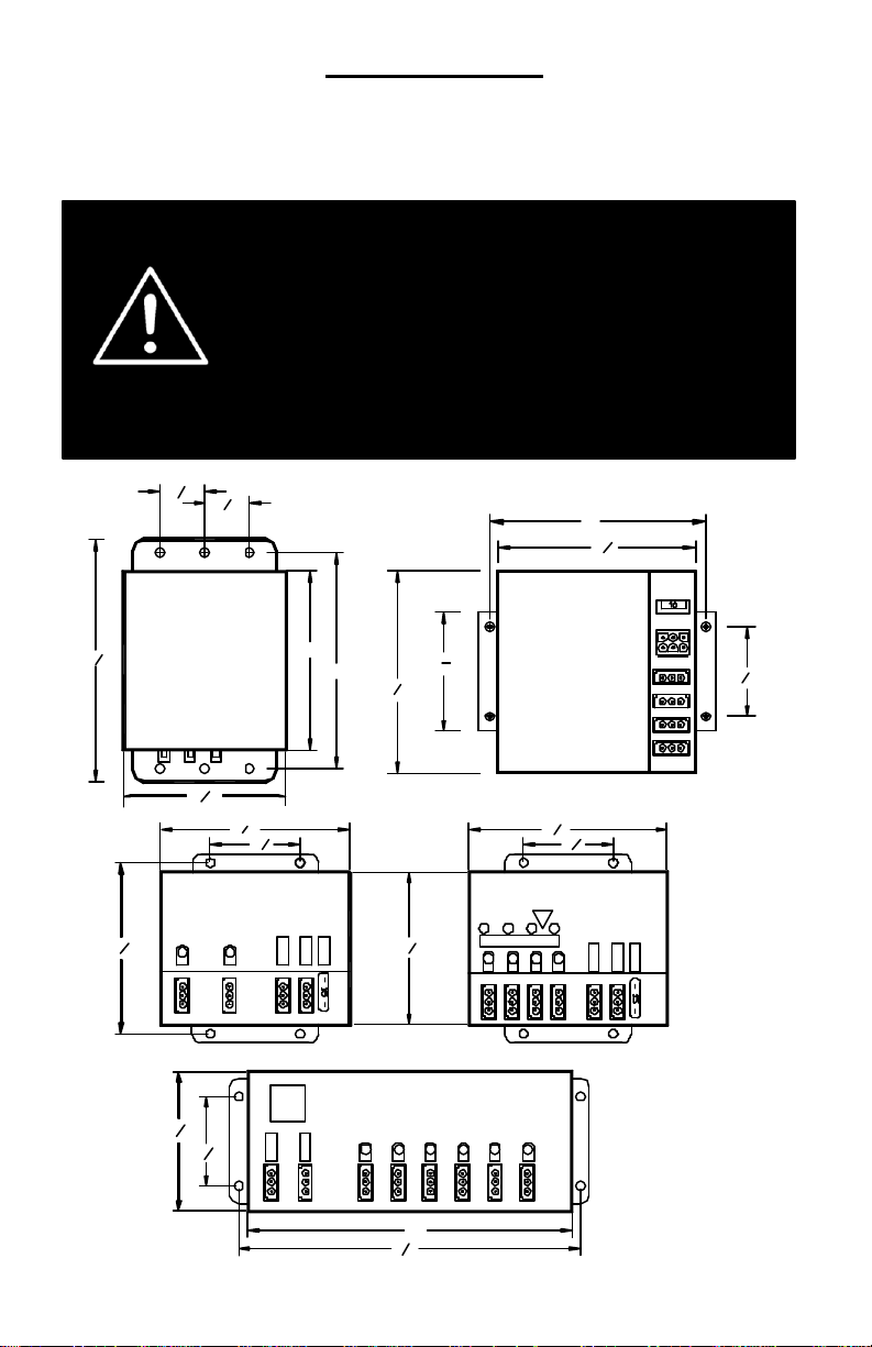
Mount the pak on a smooth metal surface to allow for adequate heat dissipation. Do not mount
Mounting the pak
the pak near any external heat source as this will retard its ability to dissipate heat sufficiently.
Mount the Pak using four bolts (not included). When mounting, make sure a good electrical
connection exists between the mounting plate and the vehicle chassis. This will help to
eliminate any RF interference.
1
When mounting the power pak and accessories, please be sure to
keep any radio frequency sensitive equipment at least 20” from the
power pak, cables, and/or wires which make up your strobe system.
The pak has been designed to limit RFI emissions, but certain very
sensitive equipment may still be affected. Symptoms may include,
but are not limited to, sporadic operation and degraded performance.
Star Headlight & Lantern Co., Inc. cannot assume any responsibility
for any radio frequency induced malfunction or damage to any
radios, sirens, lightbars, or any other equipment mounted within 20”
of this strobe system. Any antennae mounted in the proximity of the
system may cause your radio to suffer the aforementioned results.
1
"
4
1
1
"
4
6"
1
5
"
2
RP310 SERIES
3
6
"
4
1
4
"
2
1
4
"
1
"
2
OPTIMAX-RP242
3
4
" 4
L1 L2
4
7
3
"
8
1
2
"
2
PWR
CTRL
5"
6"
5
5
"
8
CTRL
15AMP
1
OPTIMAX-RP906
L1 L2 L4 L6L5
PWR
RP320/330
SERIES
15
3
"
16
1
5
"5
2
1
2
"2
2
1
2
"
2
OPTIMAX-RP244
T1
"
4
L3
T2HVT3
L2L1
L3 L4
T4
CTRL
PWR
15AMP
9"
1
9
"
2
2
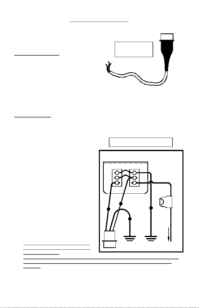
Connecting the power plug for Optimax Systems
Wiring Diagram For Optimax Systems
(RP242, RP244, & RP906)
The power plug should be included with your power
pak and comes complete with an 8-12” wiring
harness. This will be connected to the outlet on
your pak labeled PWR . Connect these wires as
follows:
BASIC ON/OFF WIRING:
(This setup is typically used for most “On/Off” applications)
A. The black wire should be connected to a good
chassis ground.
B. The red wire from your power plug should be
connected to +12VDC through your on/off
switch (optional).
C. If you are only operating your power pak with
an On/Off switch, you should leave the white
wire unconnected a nd terminate it with a wire
nut to run on constant high power.
------If you intend to utilize the HI/LO option follow the instructions below-----------
For HI/LO Operation: Make your connections as illustrated below, using the optional
A. The black (or blue) wire from your power plug on the pak should be connected to a good
chassis ground, as should the black wire from terminal 3 of SW1 on the switch panel.
B. The red wire from your power plug will
connect to the red wire extending from
terminal 2 of SW1.
C. The fused lead from terminal 1 of SW1
on the switch panel will connect to your
+12VDC power supply.
D. The white wire from the power plug
allows utilization of the HI/LO
(Day/Night Mode) option. It will be
connected to the white wire from
terminal 1 of SW2 on the switch panel.
When the white wire is connected to
power through SW2 the pak will
operate in “Night Mode” (low power).
E. When properly wired, SW1 will be on
the left side (Front View) and switch the
pack on and off. SW2 will be located
on the right side of the switch panel
and will be used to select between low
or high power.
F. Please note: When utilizing the HI/LO
option, only apply power (+12VDC) to
the white wire when
the pak is on. Applying constant voltage to the white wire from the PWR plug, while the
pak is switched off, may result in damage to the circuitry of the pak and will void the
warranty.
#SP3860-2H-OP switch available from your dealer.
PWR
CONNECT0R
POWER PLUG FOR
RP242, RP244,
AND RP906
Red = Power
Black or Blue = Ground
White = HI/LO Option
SP3860-2H-OP SWITCH PANEL (REAR VIEW)
(for use with the RP242, RP244, or RP906 Strobe Paks)
LOW
3
2
1
HIGH
SW2
WHITE
BLUE
BLACK or
RED
WHITE
PLUGS
INTO
POWER
PAK
POWER
CONNECTOR
(Connect to +12VDC for Low Power)
Utilizing the HI/LO Option
ON
3
2
1
OFF
SW1
RED
GOOD
CHASSIS
GROUND
BLACK
GOOD
CHASSIS
GROUND
15 AMP
FUSE
CONNECT TO +12 VDC
3
 Loading...