

Page 1
BKDLXT
Constellation Thinline Auxiliary LED Lights
The BKDLXT series heads utilize special connectors designed for use
with the BKLD418-2 controller (sold separately).
BKLD418
Installation Notes
• The installer must have a firm knowledge of basic electricity, vehicle electrical systems,
and emergency equipment.
• If you need to drill any holes when installing this light, please take care to check that
BOTH SIDES of your drilling surface are clear from obstructions, to ensure that you do
not damage your vehicle and or pre-existing wiring.
• Choose a mounting location away from any air bag deployment areas.
• Controls should be placed within convenient reach of the driver.
• Use only soap and water when cleaning this product. Use of other chemicals may
discolor the lens and/or housing, thus diminishing the output of the light. Lenses that
have become discolored should be replaced immediately!
• DO NOT use a pressure washer to clean this light. Use of a pressure washer may
damage the light and WILL VOID THE WARRANTY.
Wiring Notes
When wiring your lights, it is recommended that you take the following
• Keep LED modules and any radios as far away from each other as possible.
• Separate the radio wires and the LED wires.
• The Ground, Power, and Synchronization wires should be bound tightly together as
they run from light to light, through your switchbox, and finally to the battery.
precautions to reduce any Electromagnetic Interference (EMI).
Important
: This product is used to warn traffic. Improper use may result in
vehicular collision, personal injury and/or death. Star Headlight & Lantern Co.,
Inc., and its subsidiaries shall not be held responsible for damages directly or
indirectly caused by improper use of this product.
PLIT520 REV. - 8/27/14
Page 2
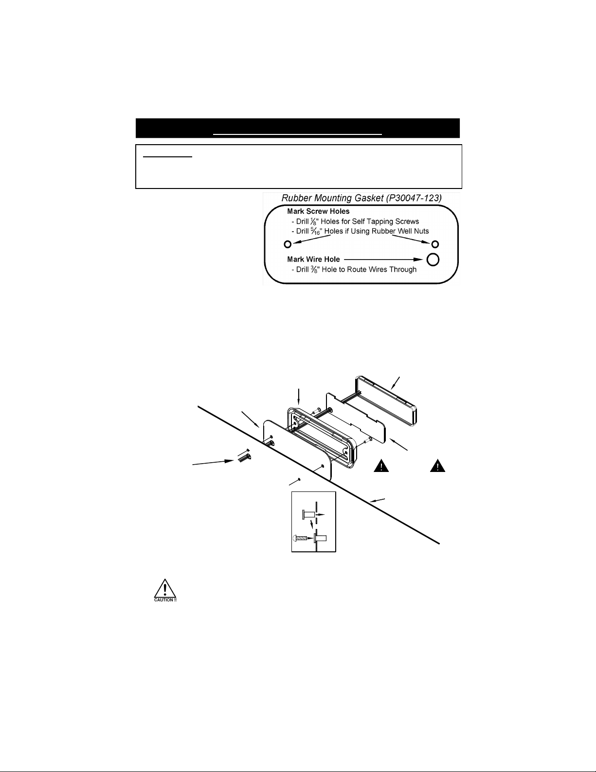
Surface Mounting Instructions
Please Note: These instructions are provided as a general guideline only. Some
vehicles may require special mounting, wiring, and/or weather-sealing. This is the
sole responsibility of the installer. Star Headlight & Lantern Co., Inc. assumes no
responsibility for the integrity of the installation for this or any of its products.
1. Use the gasket as a template
to mark your mounting holes.
2. Determine whether you are going to use the self-tapping screws or the machine screws
and well nuts.
• Use the self tapping screws for applications where the mounting surface is a minimum
of .060” (1/16”) thick and is composed of a material that will provide sufficient “bite” for
the self tapping screw.
• Use the machine screws and well nuts if your surface is less than .060” thick and/or
composed of a material insufficient for securing with self tapping screws.
3. Route the wires as
shown to the right:
Rubber Mounting Gasket
Bezel
LED Array
4. Seal the wire hole with
silicone to prevent your
wires from becoming
damaged.
WELL NUT
INSTALLATION
Foam Compression Gasket
IMPORTANT
Mounting Surface
5. If you are using the well nuts, push the
enclosed rubber well nuts through the
holes until the bottom side of the wider
lip rests on the surface of the vehicle.
6. Review the mounting diagram and use the appropriate screws to mount the bezel.
• Check the gasket to ensure it is resting flat and that there are no gaps
between the light and the mounting surface.
• Take extreme caution not to over tighten the screws!!! Over tightening
of the screws can strip the holes and result in a faulty mount.
7. Once the bezel is firmly attached to the mounting surface, seat the foam compression
gasket inside of it. Carefully feed any loose wire into the wire hole and press the LED
head into the bezel.
-2-
Page 3

Pattern Programming and Synchronization
You can synchronize up to six Constellation lights using the BKLD418-2 (sold separately).
• Lights with the SAME phase flash together (simultaneous).
• Lights with DIFFERENT phases flash opposite one another (alternate).
1. Connect all lights you want to flash
simultaneously to the BKLD418-2 and
power it up by connecting the Black wire
to ground and the Red wire to power.
2. Touch and release a screwdriver across
both Pattern Programming Pins to change
patterns.
3. After programming, remove power and disconnect the lights from the BKLD418-2.
4. Connect all of the other lights you want to flash opposite from (alternate with) the lights
you just programmed to the BKLD418-2 and power it up.
5. Touch and release a screwdriver to both Pattern Programming Pins to change patterns
until you get to the same Pattern Type, but the opposite Phase.
6. Remove power, connect all lights, and power up to test.
Single Mode
Alternating Pattern
(Programmed for opposite Phases)
Light 1
Light 2
(OFF)(ON)
(Solid Colored)
Simultaneous Pattern
(Programmed for same Phase)
Split Mode
In/Out Pattern
(Programmed for opposite Phases)
Light 2Light 1 Light 2
(ON)(OFF)
TIME
(Dual Colored)
Back & Forth Pattern
(Programmed for same Phase)
Light 1 Light 2Light 1
Please Note: Solid colored BKDLXT lights are programmed for Single Mode and dual
colored BKDLXT lights are programmed for Split Mode.
Flash Pattern #
Flash Pattern #
Phase 1
1 11 A
2 12 B
3 13 C
4 14 D
5 15 E
6 16 F
7 17 G
8 18 H
9 19 I
10 20 J
Pattern Shortcuts: Short Pattern Select Pins for indicated
time.
Steady Burn: Not in pattern cycle. Only accessible through
N/A
Pattern Type
Phase 2
Fast Singleflash (1.9 CPS)
Flicker flash (1.7 CPS)
Post pop (1.4 CPS)
PSU-flicker (0.4 CPS)
Random (1.9 CPS) (DEFAULT PATTERN)
Quadflash (1.0 CPS)
Quadflash
Singleflash (1.0 CPS)
Doubleflash (1.0 CPS)
Delta-Omega (0.3 CPS)
Steady
Pattern Description
w/Post-Pop (1.0 CPS)
(see below)
Pattern 11
Pattern 16
12 sec or 4 flashes
18 sec or 6 flashes
Shortcut
Pattern 1
(Phase 1)
3 sec or 1 flash
(Phase 2)
9 sec or 3 flashes
Pattern 6
(Phase 1)
6 Sec or 2 flash
(Phase 2)
:
:
:
:
shortcut.
-3-
Page 4

Steady Burn Programming
Programming Steady Burn Pattern in Single Mode:
1. Connect the heads you wish to be steady burn to the BKLD418-2 and power it up.
2. Hold a screwdriver across both Pattern Programming Pins until the light(s) blink(s)s six
times (approximately 18 seconds), then release it. The light(s) should change to the
Steady Burn pattern.
3. To exit Steady Burn pattern touch and release a screwdriver to both Pattern
Programming Pins.
Programming Steady Burn Pattern in Split Mode:
1. Connect heads, apply power, and program for Steady Burn as described above for
Single Mode. One of the two halves will become steady, while the other flashes.
2. To change the pattern on the flashing side, touch and release a screwdriver to both
Pattern Programming Pins.
3. To flip-flop the steady side and the flashing sides, hold a screwdriver across both
Pattern Programming Pins until the light flashes 5 times (approximately 15 seconds) and
then release it.
4. To exit Steady Burn pattern hold a screwdriver across both Pattern Programming Pins
until the light(s) blink(s) six times (approximately 18 seconds), then release it.
The manufacturer warrants this LED light against factory defects in material and workmanship for five years
LED FIVE YEAR LIMITED WARRANTY
after the date of purchase. The owner will be responsible for returning to the Service Center any defective
item(s) with the transportation costs prepaid. The manufacturer will, without charge, repair or replace at its
option, products, or part(s), which its inspection determines to be defective. Repaired or replacement
item(s) will be returned to the purchaser with transportation costs prepaid from the service point. A copy of
the purchaser's receipt must be returned with the defective item(s) in order to qualify for the warranty
coverage. Exclusions from this warranty include, but are not limited to, domes, and/or the finish. This
warranty shall not apply to any light, which has been altered, such that in the manufacturer's judgment, the
performance or reliability has been affected, or if any damage has resulted from abnormal use or service.
There are no warranties expressed or implied (including any warranty of merchantability or fitness), which
extend this warranty period. The loss of use of the product, loss of time, inconvenience, commercial loss or
consequential damages, including costs of any labor, are not covered. The manufacturer reserves the right
to change the design of the product without assuming any obligation to modify any product previously
manufactured.
This warranty gives you specific l egal rights. You might also have additional rights that may vary from state to
state. Some states do not allow l imitations on how long an implied warranty lasts. Some states do not allow
the exclusion or l imitation of incidental or consequential damages. Therefore, the above limitation(s) or
exclusion(s) may not apply to you.
If you have any questions concerning this or any other product,
please contact our Customer Service Department at (585) 226-9787.
If a product must be returned for any reason, please contact our Customer Service Department to
obtain a Returned Material Authorization number (RMA #) before you ship the product back.
Please write the RMA # clearly on the package near the mailing label.
Due to continuous product improvements, we must reserve the right to change any specifications and information, contained in this
manual at any time without notice. Star Headlight & Lantern Co., Inc. makes no warranty of any kind with regard to t his manual,
including, but not limited to, t he implied warranties of merchantability and fitness for a particular purpose. Star Headlight &
Lantern Co., Inc. shall not be liable for errors contained herein or for incidental or consequential damages in connection with the
furnishing, performance, or use of this manual.
NOTICE
-4-
 Loading...