

Page 1
INSTALLATION AND INSTRUCTION MANUAL
MODEL 9100LED MINIBAR
Due to continuous product improvements, we must reserve the right to change any specifications and information,
NOTICE
contained in this manual at any time without notice. Star Headlight & Lantern Co., Inc. makes no warranty of any
kind with regard to this manual, including, but not limited to, the implied warranties of merchantability and fitness
for a particular purpose. Star Headlight & Lantern Co., Inc. shall not be liable for errors contained herein or for
incidental or consequential damages in connection with the furnishing, performance, or use of this manual.
Please Note: These instructions are provided as a general guideline only. Specific
mounting, wiring, and/or weather-sealing may be necessary and are the sole
responsibility of the installer. Star Headlight & Lantern Co., Inc. assumes no
responsibility for the integrity of the installation for this or any of its products.
PLIT470 REV. - 11/17/11
Page 2
Permanent Mounting Instructions
1. IMPORTANT: Please read all of the following instructions before installing your new
warning light.
2. CAUTION: All of our DC powered warning lights are polarity sensitive. These lights are
polarity protected only if the appropriate fuse is used. All wires connected to the positive
terminal of the battery should be fused at the battery for their rated load. Testing the
light before this fuse is properly installed will void the warranty on the light.
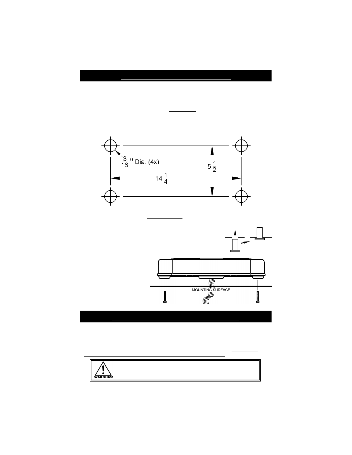
3. Permanent mount lights are mounted using four bolts that screw into molly well nuts in
each corner of the minibar. Mark the four mounting holes (and the center wire hole, if
you will be needing one). Mark the holes on the corners of a 14-1/2” x 5-1/2” rectangle.
4. Check the underside of the marked locations to ensure that you do not damage any
wires or other components. Drill a 3/16”" hole in the four marked spots for the mounting
bolts, and one in the center for your wires (if applicable).
CAUTION: Take care not to drill through the headliner below.
5. If the 4 threaded molly well nuts are not already installed in the
base of your bar, install them by pressing one into each of the
four holes found on the corners of the base of the light until the
lip rests on the bottom surface of the base.
6. Route your wires through the
center hole (if applicable) and
attach the light using the four
enclosed bolts. Insert the bolts
from below, through the holes
you drilled in the mounting
surface and screw them into
the molly well nuts on the light.
Tighten until snug.
Vacuum Magnet Mounting Instructions
If you are mounting the light on the roof of your vehicle, take extreme care to ensure that
the magnet is firmly seated on your roof, and that the pull of the magnet is sufficient to
secure the light in place. Since the composition of the metal in the roofs of different
vehicles may vary, as well as the contour, texture, and/or condition, Star cannot
guarantee the ability of the light to remain in place on a moving vehicle. It is the sole
responsibility of the owner to ensure the warning light is secure.
Care should be taken when routing the cig plug cord so that it does not
interfere with the proper operation of the driver-side or passenger-side
airbag! Failure to heed this warning may result in serious or fatal injury.
-1-
Page 3

Hard Wire Instructions
Black - (Ground) Connect to the negative side of the battery.
(Perm Mount Models)
Purple - (Optional - High/Low) Used to switch the light between High and Low power.
• Leave disconnected for High Power only (cover with wirenut or tape).
• Connect to Ground for Low Power only.
• Connect to Ground through a switch for High/Low switching option.
White - (Synchronization) Used to synchronize two lights together. If you are only installing
one unit, cut the White wire short and tape the end. If you will be synchronizing
two or more approved synchronizable lights, leave the white wire disconnected for
now. Connect the white wires from both units together ONLY AFTER
PROGRAMMING them for the same pattern (see Pattern Programming).
Red - (Power) Connect to +12-24 VDC through your switch. Be sure to use a 10 amp
Red w/Green - (Pattern Select) Touch and release to +12-24 VDC to change patterns.
fuse when connecting the switch to the positive side of the power supply.
Pattern Programming
1. To begin the programming sequence, power up the light so that it is flashing.
2. To change the flash pattern, press and release the Pattern Select Button
(cig plug models only) or briefly touch and release the Red w/Green Stripe
wire to +12-24VDC (hard-wired versions only). Repeat this to scroll
through the patterns listed below. The cycle repeats after the last pattern.
There are several patterns that you can
“jump” to via programming shortcuts. Touch
and hold the Red w/Green Stripe Wire to
+12/24VDC (or hold the Pattern Select
Button) for the length of time that corresponds
to the pattern you would like to jump to.
3. Once you find the pattern you wish to display, tape off the Red w/Green wire (hard-wire
only) and deactivate the light. This will store the selected pattern.
Flash
Pattern #
1
2
3
4
5
6
7
8
9
10
11
12
13
14
15
16
17
18
19
20
Pattern
Type
K
L
M
N
O
F
G
H
I
J
C
E
P
R
S
G
G
U
V
NONE
Alternating Flicker †
Alternating Fast Doubleflash
Alternating Tripleflash
Alternating PSU Flicker
Alternating PSU Random
Alternating Quadflash ††
Alternating Quadflash w/Post-Pop
Alternating Singleflash
Alternating Doubleflash
Alternating Variable
Post Pop
Random
Alternating Quintflash †††
Alt. Fast Doubleflash, Alt. Flicker
Alt. Quad, Alt. Flicker, Alt. Double, Flicker
Sim. Quad w/Post Pop (Phase 1) ††††
Sim. Quad w/Post Pop (Phase 2)
Alt. Triple, Alt. Non-Synch Double, Alt. Quint, Flicker
Steady burn one side, Other side Single Flash
Cycle All
† = Programming Shortcuts 1, 2, 3, and 4 (see table above)
Hold For Unit Blinks Shortcut to
3 seconds
6 seconds
9 seconds
12 seconds 4 times
1 time
2 times
3 times
Pattern 1
Pattern 6
Pattern 13
Pattern 16
Pattern List CPS
1.0
3.3
2.5
0.7
0.6
1.0
1.0
1.0
1.0
0.3
1.4
0.4
1.2
N/A
N/A
1.0
1.0
N/A
1.0
N/A
-2-
Page 4

Parts
Outer Dome ( * = color) 910-3*
Dome Gasket (Neoprene Cord) /ft P30047-145
Cig Plug (Mag Mount Only) 920-PAT18HI
Mag Mount Kit (4 Magnets) 910-177K
Vacuum Magnet 920-16V
LED FIVE YEAR LIMITED WARRANTY
The manufacturer warrants this LED light against factory defects in material and
workmanship for five years after the date of purchase. The owner will be responsible for
returning to the Service Center any defective item (s) with the transportation costs
prepaid. The manufacturer will, without charge, repair or replace at its option,
products, or part(s), which its inspection determines to be defective. Repaired or
replacement item(s) will be returned to the purchaser with transportation costs prepaid
from the service point. A copy of the purchaser's receipt must be returned with the
defective item(s) in order to qualify for the warranty coverage. Exclusions from this
warranty include, but are not limited to, domes, and/or the finish. This warranty shall not
apply to any light, which has been altered, such that in the manufacturer's judgment,
the performance or reliability has been affected, or if any damage has resulted from
abnormal use or service.
There are no warranties expressed or implied (including any warranty of merchantability
or fitness), which extend this warranty period. The loss of use of the product, loss of time,
inconvenience, commercial loss or consequential damages, including costs of any
labor, are not covered. The manufacturer reserves the right to change the design of
the product without assuming an y obligation to modify any product previously
manufactured.
This warranty gives you specific legal rights. You might also have additional rights that
may vary from state to state. Some states do not allow limitations on how long an
implied warranty lasts. Some states do not allow the exclusion or limitation of incidental
or con sequential damages. Therefore, the above limitation(s) or exclusion(s) may not
apply to you.
If you have any questions concerning this or any other product, please contact our
Customer Service Department at (585) 226-9787.
If a product must be returned for any reason, please contact our
Customer Service Department to obtain a Returned Materials Authorization
number (RMA #) before you ship the product back.
Please write the RMA # clearly on the package near the mailing label.
-3-
 Loading...