

Page 1

INSTALLATION AND INSTRUCTION MANUAL
®
LIGHTBARS
LIGHTBARS
LIGHTBARSLIGHTBARS
Owner's Manual & Installation
Owner's Manual & Installation
Owner's Manual & Installation Owner's Manual & Installation
Instructions
Instructions
InstructionsInstructions
PLITSTR328 REV D 5/22/12
Page 2
Please Note: These instructions are provided as a general guideline only. Specific
mounting, wiring, and/or weather-sealing may be necessary and are the sole
responsibility of the installer. Star Headlight & Lantern Co., Inc. assumes no
responsibility for the integrity of the installation for this or any of its products.
Due to continuous product improvements, we must reserve the right to change any specifications and information,
NOTICE
contained in this manual at any time without notice. Star Headlight & Lantern Co., Inc. makes no warranty of any
kind with regard to this manual, including, but not limited to, the implied warranties of merchantability and fitness
for a particular purpose. Star Headlight & Lantern Co., Inc. shall not be liable for errors contained herein or for
incidental or consequential damages in connection with the furnishing, performance, or use of this manual.
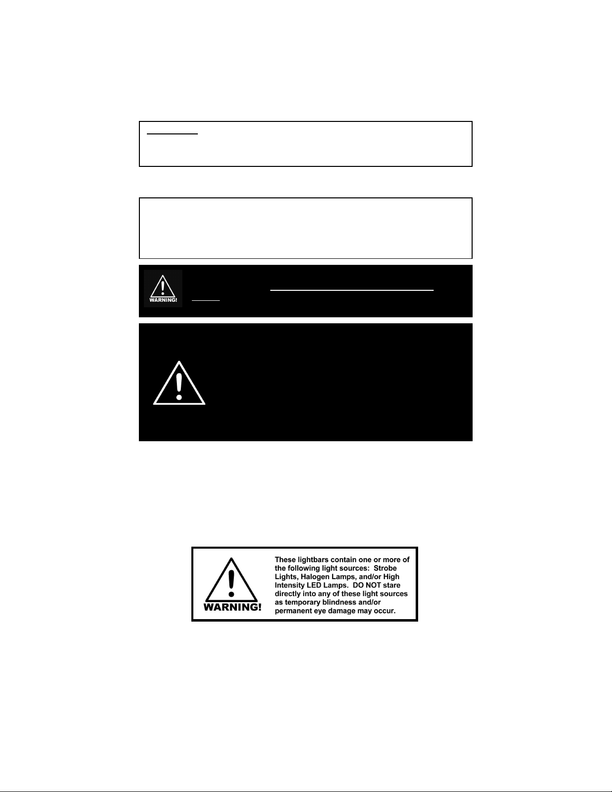
I
t is the sole responsibility of the owner to ensure the lightbar is
mounted securely. Check your light every time you enter the
vehicle to ensure that it is mounted securely. The manufacturer
assumes no responsibility for the secure mounting of this light.
When mounting your lightbar, please be sure to keep any radio frequency
sensitive equipment at least 20” from the bar and power cable(s). This is
especially critical in lightbars utilizing strobes. Our strobe power supplies
have been designed to limit RFI emissions, but certain very sensitive
equipment may still be affected. Symptoms may include, but are not
limited to, sporadic operation and degraded performance. Star Headlight
& Lantern Co., Inc. cannot assume any responsibility for any radio
frequency induced malfunction or damage to any radios, sirens, lightbars,
or any other equipment mounted within 20” of a strobe lightbar. Any
antennae mounted in the proximity of the lightbar may cause your radio to
suffer the aforementioned results.
-i-
Page 3

WARNINGS i
QUICK-INSTALL WIRING GUIDE 1
Table of Contents
MOUNTING INSTRUCTIONS 2
(For Mounting see Mounting Bracket Manual)
WIRING INSTRUCTIONS 2-9
Wire Harness Replacement 2-3
Electrical Connections 4
Wire Functions 5
Remote Power Supply Connections for Linear Strobe Heads 6-9
PATTERN PROGRAMMING 10-14
Strobe Pack Patterns 10
LED Patterns 11-14
PARTS 15-16
TROUBLESHOOTING 17-20
SERVICE
(Warranty)
21
-ii-
Page 4
QUICK-INSTALL WIRING GUIDE
All lightbars are shipped with a Wire Harness Assembly Checklist that is unique to your bar and will
define what each wire controls. You can also use the chart below for general reference.
Please note: Depending upon the components in your lightbar, the wire colors used in your
harness may differ slightly from the chart below.
Wire Harness Usage Chart
LIGHT(S) WIRE COLOR AWG
Connect to Negative Side of Battery
-12 VDC /Ground/Neutral Black 10
Connect to +12VDC
Rotating Halogen Lights Orange 14
Secondary Rotator Orange w/Black Stripe 14
360° Strobe, 360° Halo, or Strobe Power Pack* Red 14
Front Strobe Heads On/Off
Rear Strobe Heads On/Off
Pattern Select (Strobe and/or LED)‡ Red w/Green Stripe 22
Alternate Strobe Pack PWR Red w/Black Stripe 14
LED Flasher Power
LED High/Low Control Purple 18
Front Take-Down/Work Lights Green w/Yellow Stripe 14
Rear Floods/Work Lights White w/Orange Stripe 14
Front Alternating Flashers White w/Brown Stripe 16
Rear Alternating Flashers White 16
Driver’s Side Alley Light Blue 16
Passenger Side Alley Light Gray 16
Left Turn Signal Yellow 16
Right Turn Signal Green 16
Tail Lights & ID Marker Lights Brown 18
Intersection Clearing Lights White w/Blue Stripe 18
Alternate Power Red w/White Stripe 14
Traffic Director † †
‡ Please note: If you have a lightbar with a strobe pack or LED flasher, the
(4-Head Packs Only)
(4-Head Packs Only)
(LDF369 or LDF398)
* White w/Green Stripe 22
* Black w/Green Stripe 22
Orange w/Red Stripe 16
* See Remote Strobe Power Supply Connection section on pages 7-10
‡
See Pattern Programming section on page 11-13
†
Separate Bundled 9-Conductor Cable
Red w/Green Stripe wire is only used when programming the flash pattern.
This wire MUST NOT be connected to continuous +12VDC!!! Once the
pattern has been selected, tape the end of this wire off. (See page 11)
Minimum
-1-
Page 5
Mounting Instructions
Please review the separate Mounting Bracket manual that
is also enclosed with your bar for mounting instructions.
Wiring Instructions
PLEASE NOTE: If you are using the existing 15-foot cable supplied with the lightbar,
you may skip to the Electrical Connections section on page 4.
Wire Harness Replacement
If the wire supplied is too short, Star recommends direct wiring to the terminal block on
the inside of the lightbar, rather than making connections to the end of the wire that is
supplied. This lightbar is designed so that no wire connectors are needed and only a few
common tools are necessary in order to do this. Direct wiring allows the wire connections
to the lightbar to be made in a clean and dry environment, avoiding any problems that may
arise due to weathering on external connections. There is also an increase in voltage loss
with the addition of each connection. Wiring directly inside the lightbar reduces the number
of connections. However, making connections to the wires already provided is an
acceptable alternative, as long as these connections are good electrical connections and
are resistant from weathering effects. For direct wiring into the lightbar, follow the
instructions listed below.
1. Use the Wire Harness Assembly Checklist that was shipped with your lightbar or the Wire
Usage Table shown on page 1 to determine how many wires you will need to run.
2. After identifying the necessary wires, select appropriate wire sizes and colors.
3. Locate the end of the lightbar that has the external wires entering the base of the lightbar.
The black terminal block(s), which you will be making your wire terminations to, should
also be located at this same end.
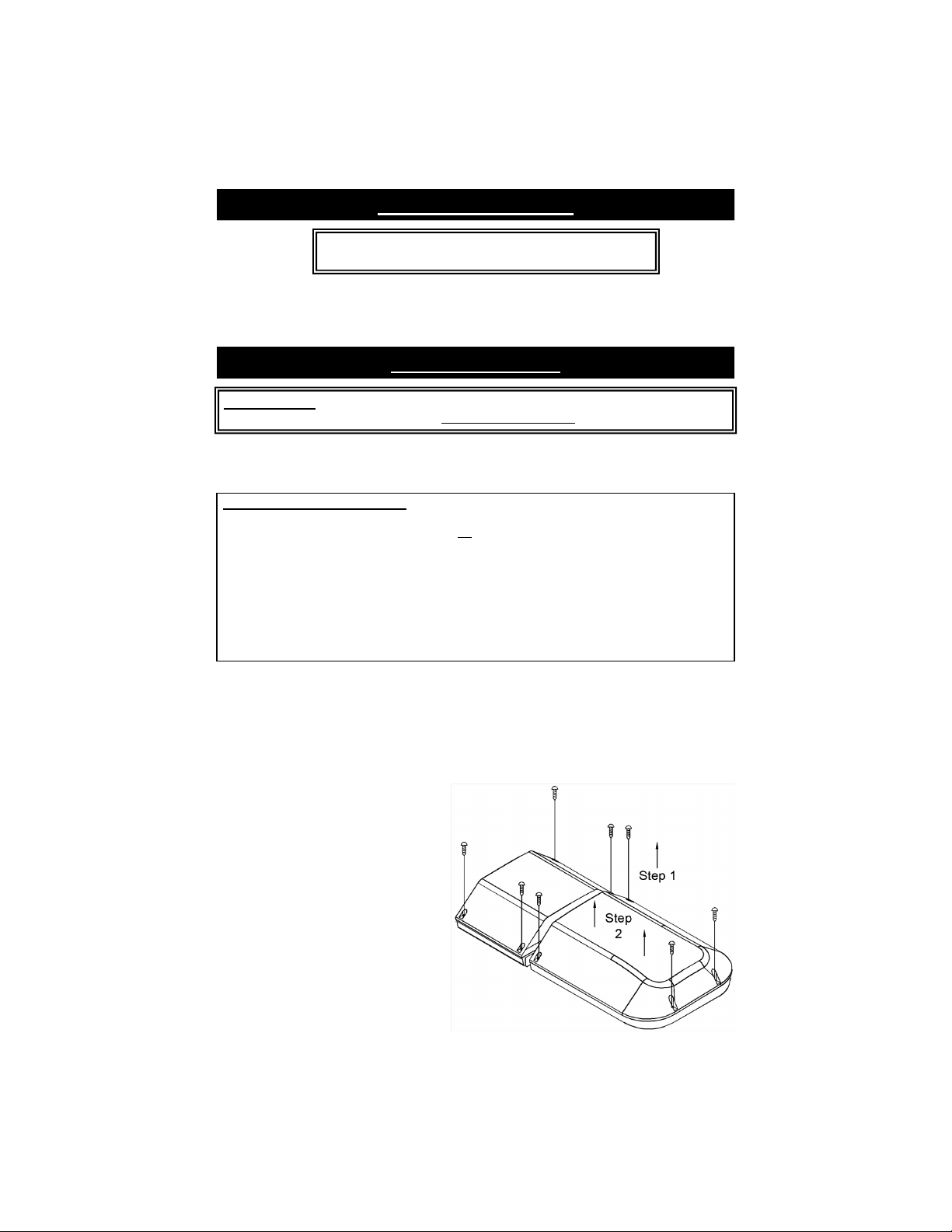
4. Remove the dome lens at this end of the lightbar:
Step 1 : Loosen the four screws
holding each dome on.
Step 2 : Lift the dome off of the base
exposing the interior
components.
Step 3 : When all work is completed,
reverse the steps to reinstall
the dome, taking care that the
gasket is properly aligned.
-2-
Page 6
(Wire Harness Replacement CONT’D)
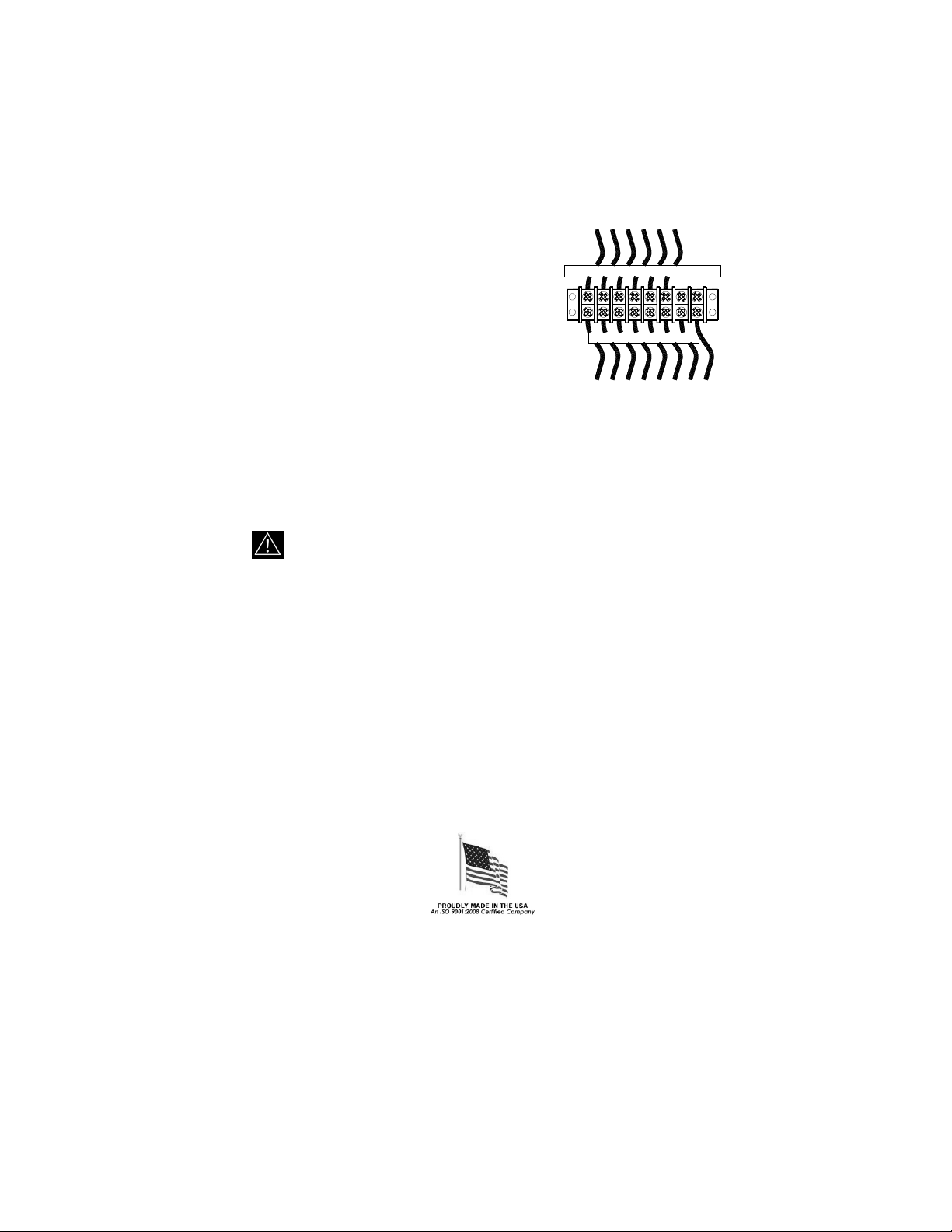
5. All of the wires coming from outside of the lightbar are
terminated on the same side of the terminal block and
the wires leading to the internal components terminate
on the opposite side of the terminal block. Loosen the
From Lightbar Components
screws on the terminal block and remove only those
wires that exit the lightbar through the hole in the
base. There may be “dead” wires from the harness
connected to the terminal block inside your lightbar, but
there will be no wires connected to the terminal across
from them. These are extra wires in the harness that are
not used. Replacing these wires in your new harness is
From Wire Harness
These
Remove
optional.
6. Run the new external wires up through the wire bushing into the base and into the
terminal block(s). The function of each of the colored wires in the original wiring harness
is listed in the Wire Harness Usage Table on page 1. There should also be a label next
to the terminal block indicating which color wire should be connected to each terminal.
7. Strip each wire 1/4". Connect the external wires to the proper poles of the terminal
block by inserting the stripped portion of the wire under the rising clamp screw and
tightening down the screw. No wire terminals are needed for connecting wires to this
terminal block.
Be sure to check that no strands of wire are loose and shorting
to the adjacent terminal or to the base of the lightbar.
The correct wire size and color listed in the table on page 1 corresponds directly with the wiring
of the lightbar. All switches used should be rated for at least 125% of their rated load.
8. When all work is completed, reverse Steps A-C in #4 to reinstall the dome, taking care
that the gasket is properly aligned.
9. Once your new wire harness has been connected to the lightbar, you may continue to
the Electrical Connections section.
-3-
Page 7
Electrical Connections
All standard lightbar models are designed for 12VDC negative ground vehicles
only. Reverse polarity will cause serious damage to the lightbar and/or vehicle.
Contact the automotive dealer if there are any doubts about the polarity of your vehicle.
RF INTERFERENCE
Please take the following steps to help eliminate any Radio Frequency Interference (RFI)
with your two-way radio.
• DO NOT run the power wire for the lightbar along same path as any antenna wires.
• DO NOT run the power wire for the lightbar along same path as any radio power wires.
• DO NOT tap power for the lightbar off of the radio power wires.
• DO NOT mount the lightbar within 20” of any antennae. Sometimes mounting the
lightbar or antenna over by just one foot can make a large difference in the interference.
• Ensure the black wire from the lightbar has a good connection to the negative side of
the battery.
Use the Wire Harness Usage Table on page 1 to identify the wire colors
and connect the appropriate wires to your switches supplying +12VDC.
• For all standard lightbars, 15 feet of cable is supplied with the bar. All wires are color
coded and sized at the correct gauge. If this length is not sufficient, it is recommended
that the wire harness be completely replaced with the only connections to be made
directly at the terminal block inside the lightbar. This will reduce the number of wire
connections and help prevent any weathering problems on these connections. Refer to
the Wire Harness Replacement section on pages 2-3 for further instructions on this.
• CAUTION: All wires and switches should be rated for at least 125% of their
maximum current load. In addition, all wires connected to the positive terminal of the
battery should be fused at the battery for 125% of their rated load. The load can be
calculated by adding all lamp wattages and dividing by 13. (Load <Amps> = Total
Watts / 13 volts) Do not use 1/4" diameter glass fuses, as they are not suitable for
continuous duty above 20 amps. A table of recommended wire colors and wire sizes is
provided on page 1. If you are unsure of the current draw, please contact our Customer
Service Department.
• TESTING THE LIGHTBAR BEFORE IT IS PROPERLY FUSED & INSTALLED WILL
VOID THE WARRANTY!!
• The black ground wire should be connected to the negative terminal of your vehicle’s
battery. This wire should be at least #10 AWG wire and be as short as possible in order
to minimize the voltage loss in this wire and reduce any chance of overheating.
• The Wire Harness Usage Table on page 1 lists the different wire colors and lights
controlled by those wires. Your harness may contain unused wires. The “dead” wires in
the harness will be connected to the terminal block inside your lightbar, but there will be
no wires connected to the terminal across from them. These “dead” wires can be used
for additional components that may be added at some point in the future, or they may be
used to separately switch components that are currently wired together.
• Since many of the lightbars we build have custom components, occasionally wire colors
may slightly vary. If you are unsure of the function of a particular wire, you may test the
function by grounding the black wire and applying +12VDC to the wire in question. Be
sure to use a 20-amp fuse when testing.
-4-
Page 8
Wire Functions
PLEASE NOTE: There are three different harnesses that could be installed on your lightbar.
Please review the Quick-Install Wiring Guide on page 1 for proper connection of your wires.
Your harness will contain all of the colored wires, the drain wire, and the foil shield, but
most applications will not use every wire. The “dead” wires in the harness will be
connected to the terminal block inside your lightbar, but there will be no wires connected
to the terminal across from them. These “dead” wires can be used for additional
components that may be added at some point in the future, or they may be used to
separately switch components that are currently wired together.
Black: (GROUND) - The black wire is the ground wire and MUST be connected
on EVERY lightbar.
Red: (Power/+12VDC) - The red wire provides the main power to the LED
flashers and/or strobe packs. Connect the red wire directly to continuous
+12VDC through a high-current fuse.
Please Note: When the red wire is connected to +12VDC the pack
will draw a small current (50 mA). If your vehicle will be
sitting for extended periods of time (i.e. more than a
few days), it is recommended the red wire be routed
through a switch or ignition switched relay.
Bare Wire: (Drain/GROUND) - This wire will help eliminate RFI. We recommend that it
be connected to ground.
Purple: (High/Low Power) - The purple wire is optional and can be used to switch
LED applications to low power. Connect the purple wire to ground to
operate the bar under low power.
Red w/Green: (Pattern Select/Touch and Release to +12VDC) - The red w/green stripe
wire is used to select the flash pattern of your LEDs or strobes. It will
normally be left unconnected. (For more detailed instructions, see
Pattern Programming on pages 8-10).
Please note: If you have a lightbar with a strobe pack or LED
flasher, the Red w/Green Stripe wire is only used when
programming the flash pattern. This wire MUST NOT be connected
to continuous +12VDC!!! Once the pattern has been selected, tape
the end of this wire off. (See pages 8-10)
All Other Colors: The remaining wires are typically On/Off controls for the lights shown in the
corresponding Quick-Install Wiring Guide on the page 1. Most applications
will not use every color wire.
Connect the wires that your lightbar utilizes to +12VDC through your switches
(not included). The “dead” wires (not needed) will be connected to the terminal
block inside your lightbar, but there will be no wires connected to the terminal
across from them. These wires do not need to be connected at the other end
of the harness.
-5-
Page 9

Remote Strobe Power Supply Connections For Linear Strobe Heads
If your lightbar contains linear strobe heads, follow the instructions below for proper wiring
of the strobe power supply. Please note that any additional lights in your lightbar must
also be connected to +12VDC through a switch. This section only discusses the proper
wiring of the strobe power supplies. For each strobe head configuration, you will be shown
two ways to wire the lightbar:
1. All strobe heads turn On and Off together
2. Separate activation of Front and Rear facing strobe heads
Lightbars with Two or Four Linear Strobe Heads
4 2
RP249-L
3
1
Four wires in your cable harness control the strobe power supply and the strobe heads
connected to it: The functions of those wires are as follows:
Red - Power to the strobe power supply
White w/Green Stripe - On/Off control for Front Linear Strobe Heads
Black w/Green Stripe - On/Off control for Rear Linear Strobe Heads
Red w/Green Stripe - Pattern Select
Activating All Strobe Heads Together
(MOST APPLICATIONS)
To turn on all four heads connected to the power supply together, connect the Red, White
w/Green Stripe, and Black w/Green Stripe together through your switch. When the switch
is thrown, all of your strobes will flash. (#1 & #4 will alternate with #2 & #3)
Harness from
Lightbar
Red
White w/Green
On/Off
SWITCH
CONNECT
TO +12 VDC
Black w/Green
Touch and Release To
Red w/Green
+12VDC to Change Pattern
DO NOT PERMANANENTLY
CONNECT Red w/Green
!
Stripe TO +12VDC!!!
Proceed to the Pattern Programming section on page 11 to program the flash pattern of your
strobe pack.
-6-
Page 10

(Strobe Pack Connections For Lightbars With 4 Linear Heads CONT’D)
Activating the Front and Rear Strobes Separately
If you would like the ability to switch the Front Strobes On and Off separate from the Rear
Strobes, connect the White w/Green Stripe wire to the switch that will activate your Front
Strobes, and connect the Black w/Green Stripe wire to the switch that will activate your
Rear Strobes.
The Red wire must be connected to constant +12VDC.
Please Note: When the red wire is connected to +12VDC the pack will draw a small
current (50 mA). If your vehicle will be sitting for extended periods of time
(i.e. more than a few days), it is recommended this wire be routed through
a switch or a high-current ignition switched relay.
Harness from
Lightbar
Front Strobes
On/Off Switch
White w/Green
Rear Strobes
On/Off Switch
Black w/Green
Red
Please Note: When the Red wire is connected to +12VDC the pack will
draw a small current (50 mA). If your vehicle will be sitting for extended
periods of time (i.e. more than a few days), it is recommended the Red wire
be routed through a switch or a high-current ignition switched relay.
CONNECT TO CONSTANT +12 VDC
CONNECT
TO +12 VDC
CONNECT
TO +12 VDC
Touch and Release To
Red w/Green
+12VDC to Change Pattern
DO NOT PERMANANENTLY CONNECT
!
Red w/Green Stripe TO +12VDC!!!
Note: If you have power to both White w/Green and Black w/Green #1 & #4 will flash together
alternating with #2 & #3. For two outlet packs, the two heads will alternate.
Proceed to the Pattern Programming section on page 11 to program the flash pattern of your
strobe pack.
-7-
Page 11

(Strobe Pack Connections For Lightbars With Linear Heads CONT’D)
Lightbars with Eight Linear Strobe Heads
4A
RP249-L
Front
(Pack A)
4B
3B 2B
2A3A
RP249-L
Rear
(Pack B)
1A
1B
Three wires in your cable harness control the strobe power supplies and the strobe heads
connected to them: The functions of those wires are as follows:
Red - Front Linear Strobe Heads On/Off
Red w/Black Stripe - Rear Linear Strobe Heads On/Off
Red w/Green Stripe - Pattern Select
Note: Heads #1 & #4 will flash together alternating with #2 & #3.
Activating All Strobe Heads Together
(MOST APPLICATIONS)
Harness from
Lightbar
To turn on all eight heads
connected to the power supply
together, connect the Red and
Red w/Black Stripe wires together
through your On/Off switch.
When the switch is thrown, all of
your strobes will flash. (#1 & #4
will alternate with #2 & #3)
Proceed to the Pattern
Programming section on page 11
Red
Red w/Black
Red w/Green
On/Off
SWITCH
CONNECT
TO +12 VDC
Touch and Release To
+12VDC to Change Pattern
DO NOT PERMANANENTLY
CONNECT Red w/Green
!!!!
Stripe TO +12VDC!!!
to program the flash pattern of your
strobe packs.
Activating Front and Rear Strobes Separately
To turn on your front strobe
Harness from
Lightbar
separately from your rear
strobes, connect the Red and
Red w/Black Stripe wires
through two separate switches.
Red
When one switch is thrown, only
the front strobes will flash. (#1 &
#4 will alternate with #2 & #3).
When the other switch is thrown
the rear strobes will flash.
Proceed to the Pattern
Programming section on page 11
Red w/Black
Red w/Green
to program the flash pattern of your
strobe pack.
-8-
Front Strobes
On/Off Switch
Rear Strobes
On/Off Switch
+12VDC to Change Pattern
DO NOT PERMANANENTLY
CONNECT Red w/Green
!
Stripe TO +12VDC!!!
CONNECT
TO +12 VDC
CONNECT
TO +12 VDC
Touch and Release To
Page 12

(Strobe Pack Connections For Lightbars With Linear Heads CONT’D)
Lightbars with Ten or Twelve Linear Strobe Heads
4A 3A
RP249-L
Front
(Pack A)
3B4B
(Pictured above is one example of a bar with 12 linear strobe heads)
RP249-L
Center
(Pack C)
4C
3C
RP249-L
Rear
(Pack B)
2C
1C
2A 1A
1B2B
Four wires in your cable harness control the strobe power supplies and the strobe heads connected
to them: The functions of those wires are as follows:
Red w/Black Stripe
Activating Front and Rear Strobes Separately
(RECOMMENDED FOR MOST APPLICATIONS)
Red w/White Stripe
Red w/Green Stripe
To turn on your front strobe heads
Red
- Front Linear Strobe Heads On/Off
- Rear Linear Strobe Heads On/Off
- Constant Power (+12 VDC) for Center Strobe Pack
- Pattern Select
Harness from
Lightbar
separately from your rear strobes,
connect the Red w/White Stripe wire to
constant +12VDC.
Please Note: When the Red w/White
Stripe wire is connected to +12VDC the
pack will draw a small current (50 mA). If
your vehicle will be sitting for extended
Red
Red w/Black
Front Strobes
On/Off Switch
Rear Strobes
On/Off Switch
CONNECT
TO +12 VDC
CONNECT
TO +12 VDC
periods of time (i.e. more than a few days),
it is recommended the Red w/White Stripe
wire be routed through a switch or a highcurrent ignition switched relay.
Then connect the Red and Red w/Black
Stripe wires through two separate
switches. When one switch is thrown,
only the front strobes will flash. (#1 & #4
will alternate with #2 & #3). When the
Red w/White
Please Note: When the Red w/White Stripe wire is connected to +12VDC
the pack will draw a small current (50 mA). If your vehicle will be sitting for
extended periods of time (i.e. more than a few days), it is recommended the
Red w/White Stripe wire be routed through a switch or a high-current
ignition switched relay.
Red w/Green
CONNECT TO CONSTANT +12 VDC
Touch and Release To
+12VDC to Change Pattern
DO NOT PERMANANENTLY CONNECT
!
Red w/Green Stripe TO +12VDC!!!
other switch is thrown the rear strobes will flash.
Proceed to the
Pattern Programming
section on page 11 to program the flash pattern of your
strobe pack.
Activating All Strobe Heads Together
To turn on all of the strobe heads in your
lightbar together, connect the Red, Red
w/Black Stripe, and Red w/White Stripe
wires together through your switch.
When the switch is thrown, all of your
strobes will flash. (#1 & #4 will alternate
with #2 & #3).
Please note: For this application,
your switch MUST be able to handle
30 amps. This configuration is
usually not recommended, since
most switches are not capable of
handling such a heavy load.
Proceed to the
Pattern Programming
section on page 11 to program the flash pattern of your
strobe pack.
Harness from
Lightbar
Red
Red w/Black
Red w/White
Red w/Green
On/Off
SWITCH
DO NOT PERMANANENTLY
CONNECT Red w/Green
!!!!
Stripe TO +12VDC!!!
CONNECT
TO +12 VDC
Touch and Release To
+12VDC to Change Pattern
-9-
Page 13

Pattern Programming
● Lightbars with strobes or LEDs can be programmed with the user’s choice of flash
pattern.
● If you have both strobes and LEDs in your lightbar,
pack(s) and LED flasher(s) must be done separately
● If you have multiple strobe packs or multiple LED flashers, all of the strobe packs can be
programmed together and all of the LED flashers can be programmed together or each
strobe pack or LED flasher can also be programmed separately, if you desire different
patterns for each.
1. To program the flash pattern turn
Strobe Pack Flash Patterns
only
the strobe pack(s) on that you wish to program.
2. Briefly touch the red w/green stripe wire to +12VDC and release it. Continue to briefly
touch and release this wire to +12VDC until you find the pattern desired. The pattern
lists for the strobe packs can be found below.
3. Once you have the pattern you like, turn the pack off. The pack will remember the
pattern next time it is activated.
4. Repeat steps 1-3 for each additional strobe pack you wish to program.
5. Once your programming is complete, tape the end of the red w/green stripe wire so that
it does not come into contact with +12VDC.
Pattern Warning Pattern Style
1 Alternating Five-Flash
2 Pseudo-Random
3 Alternating Singleflash
4 Alternating Doubleflash
5 Alternating Quadflash
The strobe packs are defaulted for Five-Flash mode. You can scroll through pseudorandom, singleflash, doubleflash, quadflash, and back to five-flash by touching and
releasing the red w/green stripe wire to +12VDC.
Please note:
If you have only the corner strobes activated (white w/yellow wire or white w/
red wire), heads 1 and 4 will alternate (see the center lightbar layout diagram on page
2). If you have only the front or rear strobes activated (brown w/yellow or brown w/
red) then heads 2 and 3 will alternate. If you activate the corners AND the fronts or
rears at the same time, heads 1 and 4 will flash together, opposite of 2 and 3.
Automatic Power Up Head Check
Each 4-outlet power pack comes with a safety feature which checks for proper operation of each
individual strobe head each time you turn on the strobe pack. This feature works by quickly
flashing each head once separately and determining if any of the heads did not flash. If two heads
normally flash together, and one fails and does not flash during the start up test, the strobe pack
will automatically reduce the output power to that particular side so that the “other” remaining
head(s) isn’t over powered. The power to that side will be reduced until the strobe pack is turned
off and on again and the faulty head tests good.
The 4-outlet strobe pack will check all four heads each time the pack is turned on EVEN if the head
select feature is being used and only two heads are to be activated. After checking all four heads,
the pack will begin flashing normally. It takes approximately 0.250 sec. to check all four heads.
Note: If you replace the non-working head, it is necessary to cycle power to the pack
before that head and the one that flashes with it will start flashing again at full
power. (You should never replace a defective head with the pack activated!!)
programming of the strobe
.
(default)
-10-
Page 14

LED Patterns
Depending upon the design of your lightbar, several different flashers can be used to flash your
LED lights. Please check the interior of the light and locate the part number of the flasher(s) that
is/are used in your lightbar. Refer to the corresponding section(s) to program the flash pattern of
your flasher.
LEDs in your lightbar are programmed using the Red w/Green stripe wire. If you have LEDs
controlled by an external flasher (LDF369, LDF398, LDF375-1, or LDF375-2), the pattern will be set
by touching the Red w/Green wire to +12VDC. If you have Halo 360º LEDs, you will set the pattern
by touching the Red w/Green wire to ground.
LED Pattern Selection for Remote LED Flashers
1. Power up the LED heads you wish to program by applying power to the appropriate wire (s)
(usually Orange w/Red Stripe for remote flashers).
2. Briefly touch the Red w/Green stripe wire to +12VDC and release it, repeating this to
scroll through the patterns listed below. The cycle will repeat itself after the last pattern.
3. Once you find the pattern you wish to select, leave the Pattern Select wire
disconnected and turn the LEDs off. This will store the selected pattern.
8-Terminal LDF369 Flash Patterns
1. Slow W arn
2. Alt. Doubleflash, Flicker
3. All Double, Alt. Pre-Pop Triple, Slow Warn
4. Alternating Doubleflash, Non-S ynch
5. Alt. Triple, Alt. Pre-Pop Triple, Flicker
6. Alt. Quad, Flicker, Alt. Double, Flicker
7. Alt. Pre-Pop Quint, Alt. Quint, Flicker
8. All Tripleflash
9. Alt. Quadflash w/Post Pop
10. All Quadflash w/Post Pop
11. Alt. Quintflash
12. One Side Steady/Other Side Singleflash
13. Alt. Pre-Pop Quintflash
14. All Flicker
15. Alt. PSU Flicker
16. One Side Steady/Other Side Short-Long †
17. One Side Rapid Fire, Other Side Pop
† =
California Title 13 Approved w/Red Steady/Blue Flashing
NOTE: If you would like to reset the pattern to the factory default (Pattern 5), simply connect the Pattern
Select wire to +12VDC for five seconds, then release it, and the default pattern will be restored.
(Default)
†
(touch Red w/Green to +12VDC)
18. Comet 1
19. Alt Long Singleflash (Medium W arn)
20. Alt. Short - Alt. Long
21. Slow Warn, Alt. Tripleflash
22. Slow W arn, Super Fast Warn
23. All Doubleflash, Alt. Doubleflash
24. All Double, Alt. Double, Flicker
25. Fast W arn
26. Superfast Warn
27. Warn Fade
28. Pre-Pop W arn
29. All Singleflash
30. Alt. Tripleflash
31. All Quintflash
32. One Side Pop, Other Side Rapid Fire
33. Comet 2
34. Delta Omega
35. Cycle All Patterns
20-Terminal LDF398 Flash Patterns
1 Pursuit Mode
2 Alternating Slow Single (1-5 vs 6-10)
3 Alternate Pursuit Mode
4 Alternating Quad Flash (1-5 vs 6-10)
5 Alternating Triple (1,2,6,7,8 vs 3,4,5,9,10)
6 Alternating Quint (1,2,6,7,8 vs 3,4,5,9,10)
7 Simultaneous Slow Single (All Modules)
8 Simultaneous Fast Single (All Modules)
9 Simultaneous Triple Flash (All Modules)
10 Simultaneous Quad Flash (All Modules)
11 Simultaneous Quint Flash (All Modules)
12 Simultaneous Fast Triple Flash (All Modules)
13 Simultaneous Fast Qui nt Flash (All Modules)
14 In/Out Single (1,2,9,10 vs 3-8)
15 In/Out Triple (1,2,9,10 vs 3-8)
(Default)
(touch Red w/Green to +12VDC)
16 In/Out Quint (1,2,9,10 v s 3-8)
17 In/Out Single (1,2,3,8,9,10 vs 4-7)
18 In/Out Triple (1,2,3,8,9,10 vs 4-7)
19 In/Out Quint (1,2,3,8,9,10 vs 4-7)
20 1-5 Steady; 6-10 Single Flash
21 1-5 Steady; 6-10 Slow Single Flash
22 6-10 Steady; 1-5 Single Flash
23 6-10 Steady; 1-5 Slow Single Flash
24 Sequential Back And Forth
25 Sequential In/Out
26 Burst All w/ Alternating Burst
27 Alternating Burst w/ Sim. Double Then Quint
28 Simultaneous Burst w/ Alt. Double Then Quint
29 Hyper-Random
30 Demo
(Cycle Through Patterns 1-4,6-9,13-20,25-29)
Please Note: You can reset the flash pattern back to the default mode (Pattern 1 – Pursuit) by holding
the red w/green Pattern Select wire to +12VDC for 5 seconds, then releasing it.
-11-
Page 15

(Remote LED Flasher Pattern Programming CONT’D)
20-Terminal LDF375-1 Flash Patterns
(Used for Front and Rear Versa Star and Batwing Heads)
(touch Red w/Green to +12VDC)
Pattern Warning Pattern Style
2 Alternating Slow Single (1-5 vs 6-10)
3 Alternate Pursuit Mode
4 Alternating Quad Flash (1-5 vs 6-10)
5 Alternating Triple (1,2,6,7,8 vs 3,4,5,9,10)
6 Alternating Quint (1,2,6,7,8 vs 3,4,5,9,10)
7 Simultaneous Slow Singl e (All Modules)
8 Simultaneous Fast Single (All Modules)
9 Simultaneous Triple Flash (All Modules )
10 Simultaneous Quad Flash (All Modules)
11 Simultaneous Quint Flash (All Mod ules)
12 Simultaneous Fast Triple Flash (All Modules)
13 Simultaneous Fast Quint Flash (All Modules)
14 In/Out Single (1,2,9,10 vs 3-8)
15 In/Out Triple (1,2,9,10 vs 3-8)
16 In/Out Quint (1,2,9,10 vs 3-8)
17 In/Out Single (1,2,3,8,9,10 vs 4-7)
18 In/Out Triple (1,2,3,8,9,10 vs 4-7)
19 In/Out Quint (1,2,3,8,9,10 vs 4-7)
20 1-5 Steady; 6-10 Single Flash
21 1-5 Steady; 6-10 Slow Single Flash
22 6-10 Steady; 1-5 Single Flash
23 6-10 Steady; 1-5 Slow Single Flash
24 Sequential Back And Forth
25 Sequential In/Out
26 Burst All w/ Alternating Burst
27 Alternating Burst w/ Simultaneous Double Then Quint
28 Simultaneous Burst w/ Alternating Double Then Quint
29 Hyper-Random
30 Pre-Pop Triple Flash
31 Alternating Pre-Pop Triple Flash
32 Demo (Cycle Through Patterns 1-4,6-9,13-20,25-29)
1 Pursuit Mode
(1 flash/3 sec default)
(3 flashes/9 sec default)
(Title 13 Approved)
(Title 13 Approved)
(2 flashes/6 sec default)
(Title 13 Approved)
(Title 13 Approved)
(Title 13 Approved)
(Title 13 Approved)
Please Note: At any time during the programming sequence, you can reset the flash
pattern back to any of the default patterns (Pattern 1, 18, or 24) by holding
the red w/green Pattern Select wire to +12VDC until the heads flash the
specified number of times, then releasing it.
Each LED flasher has 20 output terminals (10 pairs). The two terminals in each pair are
electrically connected and will flash at the same time. The numbers in parenthesis in the
list above indicate which output pairs flash together vs. the pairs they flash opposite of.
-12-
Page 16

(Remote LED Flasher Pattern Programming CONT’D)
10-Terminal LDF375-2 Flash Patterns
(Used for Versa Star or Batwing Alley Lights and Takedown/Pursuit Lights)
(touch Red w/Green to +12VDC)
Pattern Warning Pattern Style
2 Alternating Slow Single (1,3 vs 2,4)
3 Alternate Pursuit Mode
4 Alternating Quad Flash (1,3 vs 2,4)
5 Alternating Triple (1,3 vs 2,4)
6 Alternating Quint (1,3 vs 2,4)
7 Simultaneous Slow Singl e (All Modules)
8 Simultaneous Fast Single (All Modules)
9 Simultaneous Triple Flash (All Modules )
10 Simultaneous Quad Flash (All Modules)
11 Simultaneous Quint Flash (All Mod ules)
12 Simultaneous Fast Triple Flash (All Modules)
13 Simultaneous Fast Quint Flash (All Modules)
14 In/Out Single (1,3 vs 2,4)
15 In/Out Triple (1,3 vs 2,4)
16 In/Out Quint (1,3 vs 2,4)
17 Simultaneous Double Flash, Post-Pop
18 Simultaneous Triple Flash, Post-Pop
19 Simultaneous Quint Flash, Post-Pop
20 Alternating Double Flash, Post-Pop (1,3 vs 2,4)
21 Alternating Triple Flash, Post-Pop (1,3 vs 2,4)
22 Alternating Quint Flash, Post-Pop (1,3 vs 2,4)
23 Alternating Pre-Pop Qui nt Flash (1,3 vs 2,4)
24 Sequential Back And Forth
25 Sequential In/Out
26 Burst All w/ Alternating Burst
27 Alternating Burst w/ Simultaneous Double Then Quint
28 Simultaneous Burst w/ Alternating Double Then Quint
29 Hyper-Random
30 Demo (Cycle Through Patterns 1-4,6-9,13-20,25-29)
1 Pursuit Mode
(1 flash/3 sec default)
(Title 13 Approved)
(Title 13 Approved)
(2 flashes/6 sec default)
(3 flashes/9 sec default)
The numbers in parenthesis in the list above indicate which output pairs flash
together vs. the pairs they flash opposite from.
Please Note: Please Note: At any time during the programming sequence, you can reset
the flash pattern back to any of the default patterns (Pattern 1, 18, or 24) by
holding the red w/green Pattern Select wire to +12VDC until the heads flash
the specified number of times, then release it.
-13-
Page 17

(LED Pattern Programming cont’d)
360º Halo Head Flash Patterns
(touch Red w/Green to Ground)
1. Power up the LED heads you wish to program by applying power to the appropriate wire (s)
(usually Red for Halo heads).
2. Briefly touch the Red w/Green stripe wire to ground and release it, repeating this to scroll
through the patterns listed below. The cycle will repeat itself after the last pattern.
3. Once you find the pattern you wish to select, leave the Pattern Select wire
disconnected and turn the LEDs off. This will store the selected pattern.
360º Halo™ Flash Patterns
(touch Red w/Green to ground)
Flash
Pattern
Pattern #
1 K
2 L Fast Doubleflash 3.3
3 M Tripleflash † 2.5
4
5
6 F
7 G
8 H
9 I
10 J Variable AKA Delta-Omega 0.3
11 C Post pop 1.4CPS † 1.4
12 E Random 0.4CPS 0.4
13 K
14 L Fast Doubleflash 3.3
15 M Tripleflash † 2.5
16
17
18 F
19 G
20 H Singl eflash †‡ 1
21 I
22 J Variable AKA Delta-Omega 0.3
23 C Post pop 1.4CPS † 1.4
24 E Random 0.4CPS 0.4
NA N/A Steady NA
† - Approved patterns for SAE J845
‡ - California Title 13
To set the light to one of the
for the appropriate time as stated in pattern list.
Phase Pattern Description CPS Pattern Defaults
Type
N
A5
O
A6
N
A5
O
A6
Flicker † 1
PSU Flicker (Non-Rotating Models)
CCW Rotation 1 (Rotating Models) †
PSU Random (Non-Rotating Models)
CCW Rotation 2 (Rotating Models)
1
Quadflash †‡
Quadflash w/Post-Pop †‡
Singleflash †‡
Doubleflash †‡
Flicker † 1
PSU Flicker (Non-Rotating Models)
CW Rotation 1 (Rotating Models) †
PSU Random (Non-Rotating Models)
CW Rotation 2 (Rotating Models)
2
Quadflash †‡
Quadflash w/Post-Pop †‡
Double flash †‡
Pattern Defaults,
hold the P attern Select wire to GROUND
0.7
1.3
0.6
2.7
0.7
1.3
0.6
2.7
3Sec
(Non-Rot ating Only)
3Sec
(Rotating Only)
9Sec
6Sec
(Non-Rot ating Only)
9Sec
(Rotating Only)
12Sec
18Sec
1
1
1
1
1
1
1
-14-
Page 18

Parts
Bulbs and Tubes
LST129-4
4.5" LINEAR STROBE TUBE
LST129-7
7" LINEAR STROBE TUBE
ST3901-7
360° STROBE HEAD
2073-795X
50-WATT HALOGEN BULB
(Rotators, Work Lights , Takedowns, Flashers, etc.)
2073-1157
STOP-TURN-TAIL BULB
2073-H27
27-WATT HALOGEN BULB
(LOWER LEVEL)
2073-94
INCANDESCENT DIRECTIONAL
ARROW BULB
Mirrors
820-29C
MEDIUM V-MIRROR FOR CENTER
SECTION OF INTERCEPTOR
820-29
MEDIUM V-MIRROR FOR INTERCEPTOR
820-292
MEDIUM DOUBLE V-MIRR OR FOR
INTERCEPTOR
920-29
LARGE V-MIRROR
820-2*
R
L
LIGHTNING MIRROR FOR INTERCEPTOR
(*=L or R)
920-30
WALL MIRROR
(*=L or R)
Miscellaneous
820-39-PB
DIRECT MOUNT KIT
HOOK MOUNTS
THESE ARE PICTURE D IN THE HOOK
MOUNT MANUAL AND WOR K IN
CONJUNCTION WIT H THE 820-39P*
* = COLOR (White, Blac k, Clear, or Gray)
30047-61
DOME GASKETING (1 FOOT)
30053-33
TOP DOME SCREWS
920-37
SINGLE ID/MARKER LIGH T FOR 820-38-1
820-36
TRIPLE I.D./MARKER LIGHT BRACKET ONLY
TRIPLE I.D./MARKER LIGHT BRACKET
WITH THREE 920-27 ID LIGHTS
820-38-1
Please note that these it ems are not drawn to scale. Many have been enlarged to show more detail
(2.1 amps)
(2.1 amps)
(1 amp)
(0.33 amps)
(1 amp)
(1 amp)
Domes, Filters, and Lenses
820-21-*
UPPER END DOME
(*= A, B, C, G, or R)
820-22-*
UPPER CENTER DOME
(*= A, B, C, G, or R)
820-21L-*
LOWER INTERCEPTOR/SABRE
END DOME (*= A, B, C, G, or R)
820-22L-*
LOWER INTERCEPTOR/SABRE
CENTER DOME (*= A , B, C, G, or R)
920-100-*
COLOR FILTER FOR ROTA TORS
(*=A,B,G,R)
LSF4.5-*
COLOR FILTER FOR 4.5" SH3964
STROBE HEAD (*=A,B,G,R)
LSF7-*
COLOR FILTER FOR 7" SH3967
STROBE HEAD (*=A,B,G,R)
820-100LL-*
COLOR FILTER FOR LOWER
LEVEL LIGHTS (*=A,B,G,R)
333-*
DOME FOR 360° STROBE HEAD
(*= A, B, C, G, or R)
Power Supplies/Flashers
RP249
(9 amps)
4-HEAD REMOTE STROBE PAK
RP249A
(7 amps)
2-HEAD REMOTE STROBE PAK
820-181-SBQ
2-HEAD REMOTE STRO BE PAK and
REPLACEMENT 820-29 V-Mirror
TD77-2
TRAFFIC DIRECTOR C ONTROL BOX
LDC-TD
LED CONVERTER CIRC UIT FOR TD77-2
WHEN USED w/M-Tech HEADS
FM3662
2.9 FPS HALOGEN FLASHER
LDF398
8-OUTPUT LED FLASHER FOR M-TECH HEADS
(20 OUTPUT TERMINALS)
LDF369
2-OUTPUT LED FLASH ER FOR ALL LED HEADS
EXCEPT M-TECH & VE RSASTAR (8 OUTPUT TERMINALS)
LDF288-ICL
LED ICL FLASHER FOR A LL LED HEADS
(8 OUTPUT TERMINALS)
LDF375-1
8-OUTPUT LED FLASHER w/CRUISE
FOR VERSASTAR AND BATWING HEADS
(20 OUTPUT TERMINALS)
LDF375-2
8-OUTPUT LED FLASHER FOR
ALLEYS & TDP VERSASTA R AND BATWING HEADS
(10 OUTPUT TERMINALS)
LDF389
STT Controller for Lower Level Linear
LED Heads (820-14D1-R)
(2 amps)
-15-
Page 19

(Parts cont’d)
HR
FHR
RSH
LH1
LH2
L8H1
L8H2
DH
920-99 OR 920-99F
80FPM OR 160FPM HALOGEN
ROTATOR
ST3901-7
360° REMOTE STROBE HEAD
S920HL-1 or S920-HL2
360° 4-LED HALO HEAD
S920H8L-1 or S920-H8L2
360° 8-LED HALO HEAD
920-51
UPPER LEVEL DIRECTIONAL HALOGEN
(FLOOD/TAKEDOWN/PURSU IT)
520-51LED
UPPER LEVEL DIRECTIONAL LED
(FLOOD/TAKEDOWN/PURSU IT)
SH3964
4" LINEAR STROBE HEAD FOR
INTERCEPTOR LIGHTBARS
SH3967
7" LINEAR STROBE HEAD FOR
INTERCEPTOR LIGHTBARS
LSF-EC-*
LINEAR STROBE ENDCAP
620-D1 or 620-D1V
M-Tech LED Lighthead ( Standard or Value)
620-D1AL or 620-D1ALV
M-Tech LED Lighthead w/Left Ang le Reflector
(Standard or Value)
620-D1AR or 620-D1ARV
M-Tech LED Lighthead w/Right Angle Reflector
(Standard or Value)
620-D1LEC or 620-D1LECV
M-Tech LED Lighthead w/Left Endc ap
(Standard or Value)
620-D1REC or 620-D1RECV
M-Tech LED Lighthead w/Right End cap
(Standard or Value)
620-D1EC or 620-D1ECV
M-Tech LED Lighthead w/Endcaps
(Standard or Value)
620-D3 or 620-D3V
M-Tech LED 3-Lighthead End Asse mbly
(Standard or Value)
620-D2 or 620-D2V
M-Tech LED 2-Lighthead End Asse mbly
(Standard or Value)
620-D3EC or 620-D3VEC
M-Tech LED 3-Lighthead End Asse mbly
(Standard or Value)
220-ECL
M-TECH LEFT ENDCAP W/LENS
220-ECR
M-Tech Right Endcap w/Lens
S820-308UL-4*
BATWING LED w/UPP ER LEVEL BRACKET
S820-DLX6UL-1*
DLX6 INNER LED w/ UPPER LEVEL BRACKET
(0.8 amps max)
(0.8 amps max)
(0.8 amps max)
(0.8 amps max)
(0.8 amps max)
(0.8 amps max)
(1.6 amps max)
(1.6 amps max)
(1.6 amps max)
Lower Level ComponentsUpper Level Components
820-14 or 820-14LDH
LDH
LOWER LEVEL DIRECTIONAL HAL OGEN LIGHT
(WORKLIGHT/TAKED OWN/PURSUIT/ICL/ALLEY)
820-14STT
STT
LOWER LEVEL STOP/TAIL/TU RN
820-14D1-*
LOWER LEVEL SI NGLE LED ARRAY
(*=A,B,R,BR)
820-14D2-*
LOWER LEVEL DOU BLE LED ARRAY
(*=A,B,R,BR)
820-14D3-*
LOWER LEVEL TRI PLE LED ARRAY
(*=A,B,R,BR)
S520-308-4*
BATWING LED HEAD ONLY
S520-DLX6-1*
DLX6 LED HEAD ONLY
(FOCUSED OPTICS)
S520-DLX6-2A
AMBER DLX6 HEAD ONLY
FOR TRAFFIC DIRECTOR
S520-DLX6-3*
DLX6 LED HEAD ONLY
(MEDIUM OPTICS - FRONT/REAR )
S520-DLX6-4*
DLX6 LED HEAD ONLY
(WIDE SPREAD OPTICS - CORNERS)
520-308LL-4*
BATWING LED w/L OWER LEVEL BRACKET
520-DLX6LL-1*
DLX6 LED w/LOW ER LEVEL BRACKET
S520-DLX6-HK
DLX6 ALLEY LIGHT HOOD
Switches and Switchboxes
SP3860-1
Single Switch Switch-Panel
SP3860-2
Double Switch Switch-Panel
SP3860-3
Triple Switch Switch-Panel
SP3860-4
4-Switch Switch-Panel
SP1515
Black 4-Switch Switch Panel
SB1515
Black 4-Switch Switch-Box
SP3015
Black 4-Switch Switch Panel
(30A/20A/20A/20A)
SB3015
Black 4-Switch Switchbox
(30A/20A/20A/20A)
SB4020
WORK
LEFT
RIGHT
ROTATORS
STROBES
FLASHERS
LIGHTS
ALLEY
ALLEY
Black 6-Switch Switch Panel
(One 40A - Five 20A)
SB4040
TAKE
CORNER
GRILL
HEADLIGHT
MODE
1 2 3
DOWN
LIGHTS
LIGHTS
FLASHER
Black 4-Switch Switch Pan el w/Slide
(20A)
Please note that these items ar e not drawn to scale. Many have been enlarged to show more detail
-16-
Page 20

Troubleshooting
If a light on your bar fails to work, please refer to this section to help solve your problem.
If you still cannot resolve your problem, please contact our Customer Service
Department at 585-226-9787.
The chart below contains some basic guidelines for troubleshooting any problems you may
experience with your bar. The section following the chart will explain in further detail how to
perform some of the troubleshooting tasks.
Symptom:
One rotator spins but won't
light up
One rotator does not spin and
does not light up
More than one rotator does
not spin and does not lig ht up
One single LED light is Out LED Head needs to be replaced
One LED head does not flash Check wiring between LED head and flasher unit
Multiple LED heads not
flashing
One flashing light out
Multiple flashi ng lights out
One remote s trobe head out Check the strobe head
Multiple strobe heads out
Check bulb
Check the power wire running between the rotator and the terminal
block
Check the ground wire on the rotator
Check power to terminal block
Check the ground
Possible Solutions
Check LED head
Check power to terminal block
Check that the bar is properly grounded
Check power from terminal block to LED flasher unit
Check that the LED flasher unit is grounded properly
Check bulb
Check power wire from flasher unit to bulb
Check that the bulb is grounded
Check power to terminal block
Check that the bar is properly grounded
Check power from terminal block to flasher unit
Check that the flasher unit is grounded properly
Check the cable from the remote pack to the strobe head
Check power to terminal block
Check power to strobe pack Power Outlet (PW R)
Check power to strobe pack Control wires (CTRL)
Check that the pack is properly grounded
Check that the Red w/Green stripe wire IS NOT connected to +12VDC.
-17-
Page 21

(Troubleshooting cont’d)
Determining if the bar is properly grounded:
1. While the bar is turned on, using a test meter, measure the voltage from the base of the bar
itself to the negative post of the battery or a good chassis ground if the battery can’t be easily
reached. You may need to scrape away a bit of anodizing or paint in order to ensure a good
connection with the probe of your test meter.
2. If the difference shown is greater than .25 volts, then your ground is not sufficient.
3. If the ground is insufficient, locate the ground wire connection in your lightbar by removing the
dome over the section where the wires enter the bar. Please follow the appropriate dome
removal instructions listed earlier in this manual when removing this dome. The ground wire is
the large (10AWG) black wire attached to the inside of the lightbar base with a ring terminal.
Check the integrity of the connection of the ground wire to both the lightbar base and at the
other end to a good chassis ground.
4. While inspecting the ground wire connections you should also check that the wire itself is not
damaged. Carefully inspect the wire along its entire length, paying special attention to those
areas where the wire passes through any holes that may have sharp edges that can damage
the wire and the areas where the wire makes any sharp bends.
Checking the power to the terminal block
(Determining if the proper voltage is reaching your bar):
1. Locate the terminal block in your lightbar
To Lightbar Components
by removing the dome over the section
where the wires enter the bar. Please
follow the appropriate dome removal
instructions listed earlier in this manual
when removing this dome. After entering
the bar, the wires will be connected to the
terminal block with a number of small
Phillips head screws.
2. With the bar turned on, use a test meter to test
3. Be sure to test each wire that comes into the
4. Carefully inspect each wire in the terminal
From Wire Harness
the voltage at the terminal block. A nominal
12.5 volts should be present. Low voltage can
cause erratic flashing in strobe heads or even
complete failure of the heads. A minimum of
10.5 volts should be present for the pack to
operate properly. Low voltage in strobe lights,
flashing lights, or LEDs can result in lowered
intensity or even complete failure.
terminal block for proper voltage.
block. Check that the ends of the wires
have not frayed and shorted against one
another or against the base. This may
Blue
White w/Brown
White w/Blue
Green w/Yellow
Red
Red w/Black
Red w/White
Red w/Green
Harness
Black w/Green
White w/Green
Orange
White
Orange w/Red
Gray
Black
Bare
Blue
White w/Brown
White w/Blue
Green w/Yellow
Red (
PWR Plug Strobe Pack 1
Red (
PWR Plug Strobe Pack 2
Red w/White
Red (
CTRL Plug
To
CTRL Power Plug
CTRL Power Plug
LED Flasher
)
)
)
)
Components
From
Wire
Lightbar
Black (
White (
Orange
White
Red (
Gray
Black
Bare
cause lights to operate inadvertently or
may result in the failure of lights.
(271STROBE Cable Shown)
)
)
-18-
Page 22

(Troubleshooting cont’d)
Checking one non-working strobe or LED head:
If a problem exists in only one head
there may be an open electrical connection in the wiring harness or strobe head.
, a strobe tube or LED head may have burned out, or
1. Check connections at and between the strobe pack and the faulty strobe head or between
the flasher unit and LED head, including all wiring.
2. Disconnect both the faulty head and a working head.
3. Check the faulty head by connecting it into the side you just unplugged the working head
from. If the faulty head still does not work, then the head is bad and will need to be replaced.
4. If the head that was not flashing works when connected to the other side, the problem
probably lies in the power pack or flasher unit. Verify this by plugging the other head (the
original working head you just unplugged) into the side that previously had the non-working
head.
Checking multiple non-working strobe heads:
If the problem exists in only your strobe heads, and none of your strobe heads are
flashing, follow these steps to determine the problem:
1.
Check all fuses
, including those at the battery, at the switch panel, in the dash, and
on the pack (if applicable). The strobe power supplies all have automotive “blade”
type fuses. Remove these fuses, and check them to confirm they have not blown.
Replace any blown fuses with only fuses of identical values. Replacing the fuse with
the wrong rating may damage your pack and/or vehicle, and will void your warranty.
2.
Check the power and ground wires to your pack.
With the vehicle turned off and
while the pack is running, measure the voltage across the red wire (pin 1) and the
black wire (pin 2) of the
PWR
connector on the power pack (the one with the Black,
Black, and Purple wires). Push the probes of the test meter down into the connector
at the wire entry points to contact the terminals for the measurement. A nominal 12.5
volts should be present. Low voltage to the pack can cause erratic flashing or even
complete failure of the heads. A minimum of 10.5 volts should be present for the
pack to operate properly. If you do not have proper voltage present, your power or
ground is bad. Continue to step 3. If your pack is receiving sufficient voltage then
skip to step 5.
BLACK (GROUND)
RED (+12 VDC)
POWER
PURPLE (High/Low)
BLACK (GROUND)
BLACK (Power)
3.
Test the Power to the power supply from the terminal block.
If sufficient voltage
is not reaching the pack, and you have already determined that proper voltage is
reaching your terminal block, perform the following tests: With the vehicle turned off
and while the pack is running, measure the voltage drop in the red wire by taking a
reading from pin 1 of your Power connector (Red wire) and the corresponding wire on
the terminal block. If this reading exceeds 0.25 volts then there is a poor connection
between the terminal block and your power supply in the red wire and it should be
checked.
4.
Check the Ground wire on the pack.
troubleshoot the connections between pin 2 (black wire) of the
If you still have not located the problem,
PWR
connector on the
power pack and the lightbar base, while the lightbar is running. If this reading
exceeds 0.25 volts then there is a poor connection between the pack and the lightbar
base in the black wire and it should be checked.
-19-
Page 23

(Troubleshooting cont’d)
5.
Check that the proper voltage is reaching the necessary CTRL inputs.
Check
that the proper voltage is reaching the Black wire (across from the Black w/Green
stripe wire on the Terminal Block) and White wire (across from the White w/Green
stripe wire on the Terminal block) of the
CTRL
plug on your strobe pack with the
vehicle turned off, and while the bar is running. Measure the voltage across the Black
wire (pin 2) on the CTRL plug
(NOT THE POWER PLUG)
and the negative terminal
of your battery. Push the probes of the test meter down into the connector at the wire
entry points on the pack side of the connectors to contact the terminals for the
measurement. Note this reading. A nominal 12.5 volts should be present. A
minimum of 10.5 volts should be present for the pack to operate properly. Also,
check the voltage on the White wire. If your pack is receiving sufficient voltage to
both wires then continue to step 6. If you do not have proper voltage present on
either wire, check the wiring to the connector.
WHITE
BLACK
RED
6. C
heck the CTRL connector to be sure that +12VDC is not applied the Red wire.
CONTROL
WHITE (Heads 2 & 4)
BLACK (Heads 1 & 3)
RED (Pattern Select)
The Red wire on the CTRL connector of the strobe pack is used for pattern select.
The patterns are changed by touching AND RELEASING this wire to +12VDC. A
constant voltage applied to the Red wire on the CTRL connector will prevent the
strobe pack from flashing.
7.
Check each strobe head.
If the leads in one of the heads have shorted out, the
output voltage of the other heads may be held down as well. To test for this, unplug
all of the heads and plug them in individually, one at a time. If your problem is a result
of a shorted head, then the other heads should function properly if the faulty head is
no longer connected. Note: A burned out strobe tube does not cause a short and will
not affect the operation of the remaining heads. If the problem is not with a shorted
head and if proper voltage is reaching the pack, the problem is most likely internal to
the pack.
8. If sufficient voltage is not reaching the pack perform the following tests: With the
vehicle turned off and while the pack is running, measure the battery voltage
battery
. A nominal 12.5 volts should exist. Note this voltage. If this voltage is below
at the
10.0 volts the pack will not function properly and the problem is with the battery. This
reading should not be more than 1-1.25 volts higher than the reading in the 4th step. If
there is an excessive difference then continue on to the next step.
9. With the vehicle not running and the lightbar on, measure the voltage in the red wire
by taking a reading from the positive side of the battery to pin 1 of your switch. If this
reading exceeds 0.25 volts then there is a poor connection between the switch and
the battery in the red wire and it should be checked.
10. If you still have not located the problem, troubleshoot the connections between the
good chassis ground and pin 2 (black or blue wire) of the
PWR
connector on the
power pack, while the lightbar is running. If this reading exceeds 0.25 volts then there
is a poor connection between the switch and the ground in the black wire and it should
be checked.
11. This same procedure can be used to check the wires between the terminal block and
the pack. Place one probe on the terminal at the terminal block and the other probe
into the terminal with the corresponding wire color in the connector on the pack. Once
again if any of the readings exceed 0.25 volts then you should check those wires and
their connections.
-20-
Page 24

Service
ONE YEAR LIMITED WARRANTY
The manufacturer warrants each new product, under normal use, against factory defects in material and
workmanship for one year after the date of purchase. The manufacturer warrants the LED components in this
light against factory defects in material and workmanship for five years after the date of purchase. The
owner will be responsible for returning to the Service Center any defective item(s) with the transportation
costs prepaid. The manufacturer will, without charge, repair or replace at its option, products, or part(s),
which its inspection determines to be defective. Repaired or replacement item(s) will be returned to the
purchaser with transportation costs prepaid from the service point. A copy of the purchaser's receipt must be
returned with the defective item(s) in order to qualify for the warranty coverage. If a copy of the receipt is
not provided, the warranty period shall cover five years from the date of manufacture.
Exclusions from this warranty include, but are not limited to, bulbs, strobe tubes, domes, and/or the finish. This
warranty shall not apply to any light, which has been altered, such that in the manufacturer's judgment, the
performance or reliability has been affected, or if any damage has resulted from abnormal use or service.
This warranty does not apply to defect or damage occurring as a result of disaster, accident, abuse, misuse,
lightning, power surges, or failure to follow instructions in any enclosed manuals. Any damage or defects
occurring as a result of any unauthorized service or repairs by unauthorized persons shall be excluded from
this warranty.
There are no warranties expressed or implied (including any warranty of merchantability or fitness), which
extend these warranty period. The loss of use of the product, loss of time, inconvenience, commercial loss or
consequential damages, including costs of any labor, are not covered. The manufacturer reserves the right
to change the design of the product without assuming any obligation to modify any product previously
manufactured.
This warranty gives you specific legal rights. You might also have additional rights that may vary from state to
state. Some states do not allow limitations on how long an implied warranty lasts. Some states do not allow
the exclusion or limitation of incidental or consequential damages. Therefore, the above limitation(s) or
exclusion(s) may not apply to you.
LED FIVE YEAR LIMITED WARRANTY
If you have any questions concerning this or any other product, please contact our
Customer Service Department
at (585) 226-9787.
If a product must be returned for any reason, please contact our Customer Service
Department to obtain a Returned Materials Authorization number (RMA #) before you ship
the product back. Please write the RMA # clearly on the package near the mailing label.
-21-
 Loading...