

Page 1
INSTALLATION AND INSTRUCTION MANUAL
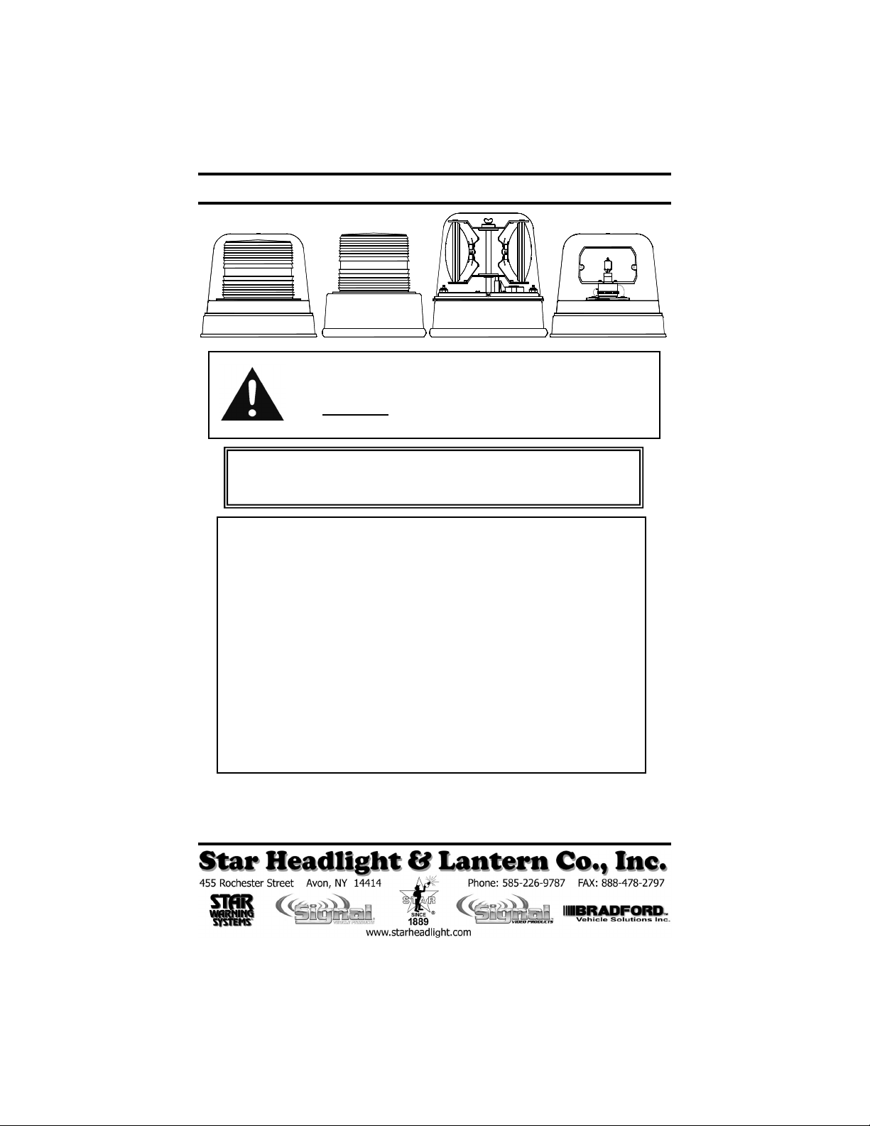
200A SERIES
200C SERIES
200E SERIES
400A
450A SERIES
CAUTION: All of our DC powered warning lights are polarity sensitive.
These lights are polarity protected only if the appropriate fuse is used.
All wires connected to the positive terminal of the battery should be
fused at the battery for their rated load. Testing the light before this
fuse is properly installed will void the warranty on the light.
These lights are standard negative ground. Isolated or floating units for
positive ground vehicles are clearly labeled and are available upon request. In
this case connect the power to the proper polarity as marked on the wires.
ONE YEAR LIMITED WARRANTY
The manufacturer warrants each new product against factory defects in material and
workmanship for one year after the date of purchase. The owner will be responsible for returning
to the Service Center any defective item(s) with the transportation costs prepaid. The
manufacturer will, without charge, repair or replace at its option, products, or part(s), which its
inspection determines to be defective. Repaired or replacement item(s) will be returned to the
purchaser with transportat ion costs prepaid from the service po int. A copy of the purchaser's
receipt must be returned with th e defective item(s) in order to qualify for the warranty coverage.
Exclusions from this warranty include, but are not limited to, bulbs, strobe tubes, domes, and/or the
finish. This warranty shall not apply to any light, which has been altered, such that in the
manufacturer's judgment, the performance or reliability has be en affected, or if any damage has
resulted from abnormal use or service.
There are no warranties expressed or implied (including any warranty of merchantability or fitness),
which extend this warranty period. The loss of use of the product, loss of time, inconvenience,
commercial loss or consequential damages, including costs of any labor, are not covered. The
manufacturer reserves the right to change the design of the product without assuming any
obligation to modify any product previously manufactured.
This warranty gives you specific le gal rights. You might also h ave additional rights that may vary
from state to state. Some states do not allow limitations on how long an implied warranty lasts.
Some states do not allow the exclusion or limitation of incidental or consequential damages.
Therefore, the above limitation(s) or exclusion(s) may not apply to you.
If you have any questions concerning this or any other product,
please contact our Customer Service Department at (585) 226-9787.
If a product must be returned for any reason, please contact our Customer Service Department
to obtain a Returned Materials Authorization number (RMA #) before you ship the product back.
Please write the RMA # clearly on the package near the mailing label.
PLITSTR101 REV. E 9/16/11
Page 2
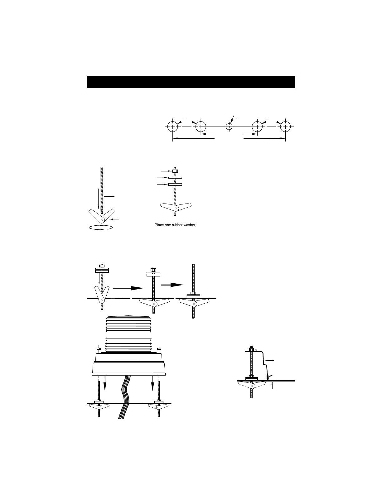
Mounting Toggle Wing Models
1. Your new warning light comes complete with a rubber mounting gasket, 2 toggle wings,
2 threaded rods, 2 neoprene washers, 2 steel washers, 2 nuts, and 2 self-locking nuts.
2. Mark two mounting holes on
7” centers for the 400A, and
450A Series or 3½” centers
5
" DIA.
8
for the 200C or 200E series
and mark a spot for the wire
hole centered directly
between them.
3. Drill a 5/8" hole in the outer two marked locations. Then drill a 3/8" hole in the center
marked location for your wires to run through. CAUTION: Take care not to drill through
the headliner of the vehicle.
NUT
STEEL WASHER
RUBBER WASHER
THREADED ROD
4. Attach the rubber mounting gasket
around the base of the light.
5. Carefully remove the lens by
removing the three screws at the base
of the lens. Lift off the lens and
remove it taking care to ensure you do
not lose or destroy the lens gasket.
6. Attach a toggle wing to one end of one
of each of the threaded rods.
7. Place the rubber and steel washers
around each of the threaded rods
according to the diagram to the left.
Screw toggle wing
and threaded rod
together
TOGGLE WING
one steel washer, and
one nut on each rod
8. Then push the toggle wing through the top of one of the outer holes in the mounting
surface until it opens under the mounting surface.
WIRE HOLE
3
8
3½" CENTERS
7" CENTERS
" DIA.
5
" DIA.
8
Insert the threaded rod
and toggle wing
through the mounting
surface
MOUNTING SURFACE
Route wires through center hole, slide
light over rods, and secure with nuts
Tighten the nut,
securing the rod in
place
9. Tighten the nut down such
that it seats the steel washer
firmly against the rubber
washer, and the mounting
surface, holding the rod in
place. Repeat this for each
threaded rod.
10. Route the wires through the center hole, align
the outer holes in the base with the threaded
rods and slide the base onto the rods.
11. Fasten one of the
self-locking nuts to
each of the threaded
rods and tighten
until snug.
12. Once all of the nuts are tight and the base is
secure, reattach the outer lens(es).
-1-
SELF -LO CKI NG NUT
BASE
MOUNT ING
GAS KET
MOUN TING
SURF ACE
Page 3

Mounting Plastic Base Models
Remove the 4 screws in the
side of the Aluminum housing
and slide the plastic base out
Gasket
Plastic Mounting Base
3 Locate the various knockouts on the bottom
of the base and determine which mounting
holes will work best for your application.
Clear the knockouts using a punch or other
appropriate tool.
4. Using the plastic mounting base as a
template, mark the appropriate holes on the
mounting surface. Take care to ensure that
the base does not move while you are
marking each of the holes.
1. Remove the four screws in the side
of the aluminum housing.
2. Slide the plastic base out of the
aluminum case. Take care not to
damage the gasket when separating
the plastic base from the aluminum
case.
0.196" Diameter
on 2.975" Radius
3 @ 120°
0.264" Diameter
on 2.5" Radius
2 @ 180°
101-AP
0.261" Diameter
on 3.125" Radius
3 @ 120°
1" NPT THREADED
PIPE MOUNT
0.189" Diameter
on 1.75" Radius
2 @ 180°
5. Remove the plastic mounting base and drill a 3/8" hole in the marked locations. Then, if
applicable, drill a 3/8" hole for the wires in the center of the outer holes.
CAUTION: Take care not to drill through the headliner of the vehicle below.
6. Push the enclosed rubber well nuts through the outer holes until the
bottom side of the wider lip rests on the surface of the vehicle.
7. Route the wires through the center hole, if applicable and align the holes with the well
nuts. Install the screws through the base, into the well nuts, and tighten until snug.
8. Once the plastic mounting base is installed on the vehicle, you may replace the light on
the base and reinstall the four screws that affix the light to the plastic mounting base.
-2-
Page 4

Wiring
1. For 110/120VAC models, the black and white wires may be connected either way
(polarity is not important).
2. For all other models, the black or white wire on your light is the ground lead and should
be connected to a good chassis ground.
3. The red wire on your light should be connected to the positive side of the power through
a fused switch, checking your warning light for proper voltage and amperage.
4. If you are installing a single-flash, 12-48 VDC, or rotating model, you are now finished
and may skip the remaining steps.
5. For strobe models with a purple wire:
If your light comes with a purple wire, it has the ability to switch between Low and High
power (if desired).
To run on High Power Only:
Connect the Purple wire with the
Black wire to Ground.
To run on Low Power Only:
Disconnect the Purple wire (or
cut it short and tape it off).
If you intend to make use of the
High/Low option through a switch,
refer to the wiring diagram to the
right for proper connections using
a two-switch switch panel
available from Star. When the
purple wire is grounded through
your switch, the light will operate
under High Power.
LED Indicator
These lights also have an LED Diagnostic Indicator.
The LED indicator is designed to flash when the strobe
tube should be flashing. If a strobe light is not working,
troubleshooting becomes easy with this new LED.
Simply examine the circuit when power is applied to it.
If the strobe tube is not
flashing, but the LED is flashing, you have a bad strobe
tube. If the LED is not flashing, the circuit is either not
receiving the proper voltage, or the circuit has failed.
Pattern Select Jumper
The circuits now found in these lights have a jumper on them allowing the end user to select
the desired flash pattern (singleflash, doubleflash, or quadflash). If you wish to change the
pattern, activate the light and follow the instructions below.
1. The Pattern Select Jumper is stored on pins 1 & 2.
2. To change the pattern, remove the jumper from pins 1 & 2,
momentarily place it over pins 2 & 3, then remove it. The
pattern should advance to the next.
3. Continue to touch and release the jumper to pins 2 & 3 to
cycle through the patterns:
4. Once you have selected a pattern, replace the jumper on
Singleflash Doubleflash Quadflash
pins 1 & 2.
SP3860-2H SWITCH PANEL (REAR VIEW)
WARNING
BLACK
GOOD
CHASSIS
GROUND
LIGHT
HIGH
LOW
RED
PURPLE
PURPLE
MALE TERMINAL
3
2
1
RED
(FOR BLACK WIRE)
3 2 1
MALE TERMINAL
(FOR BLACK WIRE)
3 2 1
ON
3
2
1
OFF
SW1SW2
S8070-159-14
RED LEAD w/FEMALE TERMINAL
PATTERN SELECT
JUMPERS
MALE TERMINAL
(FOR PURPLE WIRE)
PATTERN SELECT
BLACK
10 AMP
FUSE
CONNECT RED
FUSED LEA D TO
+12 VDC
(FOR RED WIRE)
3 2 1
S8070-159-14
RED LEAD w/FEMALE TERMINAL
JUMPERS
3 2 1
MALE TERMINAL
(FOR PURPLE WIRE)
(FOR RED WIRE)
GOOD
CHASSIS
GROUND
DIAGNOSTIC
LED
DIAGNOSTIC
LED
-3-
 Loading...