

Page 1
274
274----RCK
274274
RCK
RCKRCK
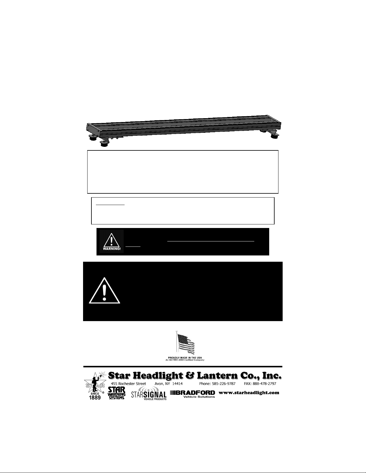
Universal Rooftop Mounting Rack
NOTICE
Due to continuous product improvements, we must reserve the right to change any specifications
and information, contained in this manual at any time without notice. Star Headlight & Lantern
Co., Inc. makes no warranty of any kind with regard to this manual, including, but not limited to,
the implied warranties of merchantability and fitness for a particular purpose. Star Headlight &
Lantern Co., Inc. shall not be liable for errors contained herein or for incidental or consequential
damages in connection with the furnishing, performance, or use of this manual.
Please Note: These instructions are provided as a general guideline only. Some
vehicles may require special mounting, wiring, and/or weather-sealing. This is the
sole responsibility of the installer. Star Headlight & Lantern Co., Inc. assumes no
responsibility for the integrity of the installation for this or any of its products.
It is the sole responsibility of the owner to ensure the lightbar is
mounted securely. Check your light every time you enter the
vehicle to ensure that it is mounted securely. The manufacturer
assumes no responsibility for the secure mounting of this light.
When mounting your lightbar, please be sure to keep any radio frequency
sensitive equipment at least 20” from the bar and power cable(s). This is
especially critical in lightbars utilizing strobes. Our strobe power supplies have
been designed to limit RFI emissions, but certain very sensitive equipment
may still be affected. Symptoms may include, but are not limited to, sporadic
operation and degraded performance. Star Headlight & Lantern Co., Inc.
cannot assume any responsibility for any radio frequency induced malfunction
or damage to any radios, sirens, lightbars, or any other equipment mounted
within 20” a strobe lightbar. Any antennae mounted in the proximity of the
lightbar may cause your radio to suffer the aforementioned results.
PLITSTR184 REV. D 12/20/12
Page 2
Prior to starting your installation, please read through all of the instructions to
familiarize yourself with the installation of the bar AND any components that you may
be mounting to the bar. Based upon your application, determine whether you wish to
install the bar on the vehicle first, then add your components, or whether you wish to
install any or all of your components onto the bar first.
Tow Mounts
If your bar came equipped with the tow mounts, simply loosen
the 4 nuts securing each mount, slide it to the desired position,
and re-tighten them.
Hook Mounts
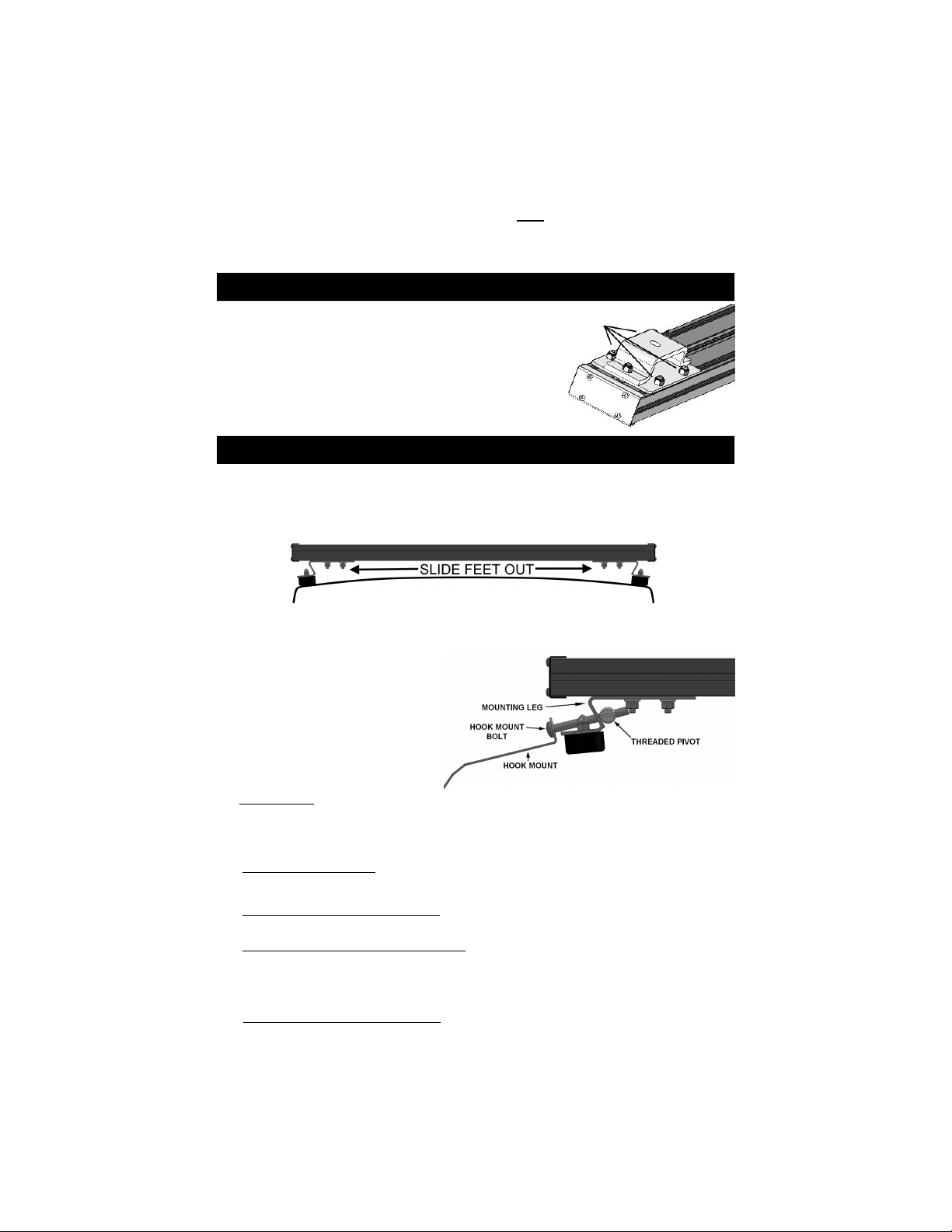
1. Carefully place your lightbar in position onto the roof of the vehicle and slightly loosen
the nuts that hold the mounting legs to the extrusion. The tabs on the mounting feet can
be bent slightly to an angle that matches the curvature of the roof, if necessary.
2. Slide the mounting brackets (legs) as close to the edge of the roof as possible.
3. Once the lightbar is in the correct position, level front to back and centered side-to-side,
tighten hex nuts securing the mounting brackets to the extrusions.
4. Attach the optional hook mounts to
each bracket using the bolt
provided with the mounts. Slip the
bolt through the hole in the hook
mount bracket and through the
hole in the mounting leg, then
screw it into the threaded pivot in
the mounting leg.
Please Note: For some applications, the bolt we provide may not be long
5. If using a Gutter Hook, tighten the bolt on one mounting bracket until the hook is just
under the gutter. Repeat this on the other side. Then alternate sides, tightening each
bolt approximately 1/2 turn until the mount is secure.
Do not over-tighten either mount! It is not necessary to dimple the roof in order to
achieve a secure, stable mount.
6. If you are installing a gutterless hook, tighten the bolt until the gutterless hook lip just
touches the inside lip of door jamb. Drill two or three holes and install the two sheet
metal screws through the enclosed rubber washers to secure the gutterless hook on the
inside lip of the door jamb. Repeat this for the other side of the bar. Then alternate
sides, tightening each bolt approximately 1/2 turn until the mount is secure.
Do not over-tighten either mount! It is not necessary to dimple the roof in order to
achieve a secure, stable mount.
enough. If the mounting brackets are fully extended and the hook
mounts still will not reach the edge of the vehicle, you may use a
longer 5/16"-18 bolt obtained locally.
-2-
Page 3

Component Installation
Installation of most optional components will require temporary removal of the end caps to
slide bolts onto the extrusion and/or to run wiring inside the extrusions. Proceed as follows:
1. Remove the four screws
securing one of the endcaps on
the 274-RCK and slide the
endcap off.
If you have a traffic director
version, remove the endcap
from the end OPPOSITE the
cable.
When reinstalling, ensure the
gasket is seated properly so
that it will not leak.
2. If you wish to route any wires from your components
around the bottom of the extrusion and inside of it,
it is recommended that you remove the front
extrusion to allow for easy access to the
inside of the rear extrusion.
A. Loosen any nuts that secure any mounting plates/brackets to the front extrusion.
(shown with optional traffic director)
B. Loosen the two nuts on each mounting bracket that secures the
mounting brackets to the front extrusion.
C. Remove the four screws securing
both endcaps to the extrusion and
slide the endcaps off.
D. Slide the front extrusion off the bolts attaching
the mounting legs and strobe light plate.
3. If necessary, slide the plastic “window” out of the rear
extrusion exposing the inside of the rear extrusion. (Your
rack may come with the window separate.)
-3-
Page 4

(Component Installation CONT’D)
4. Determine where you wires from your
components will wrap under the bar and enter
the extrusion and cut the plastic window to the
desired length.
• Using a sharp utility knife, heavily score a
“snap” line on the plastic.
• Bend the plastic back and forth about the
scored line until it breaks.
5. Route the wires from the first light under the extrusions (or over the top of the extrusion,
if applicable), connect them to the appropriate wires from the harness, and tuck the
connectors into the extrusion.
6. Measure the distance to the
wires from the next light and cut
another length of the plastic
window. Slide it into the
designated slot in the extrusion
as close as possible to the wires
from the first light.
7. Repeat steps 4-6 for each light you need to connect, cutting the last plastic window
piece to extend to the end of the extrusion.
8. Once all plastic window pieces are in place, slide the front extrusion over the bolts and
back onto the assembly.
9. If you are adding mounting plates/brackets, slide any
appropriate bolts into each slot based upon your application(s).
10 Replace the end cap and re-install the screws.
DO NOT OVER-TIGHTEN THE SCREWS. IF THE
SCREW HOLES ARE STRIPPED, THE SECURE
MOUNTING OF YOUR COMPONENTS MAY BE
COMPROMISED.
-4-
 Loading...