

Page 1
INSTALLATION AND INSTRUCTION MANUAL
SAEJ1318 Class II : 255TS, 255TC, 257TS, 257TC (Quadflash Mode)
255HTC (Red)
SAEJ1318 Class I : 255HTC (Amber/Blue/Clear)
Please Note: These instructions are provided as a general guideline only. Some
vehicles may require special mounting, wiring, and/or weather-sealing. This is the
sole responsibility of the installer. Star Headlight & Lantern Co., Inc. assumes no
responsibility for the integrity of the installation for this or any of its products.
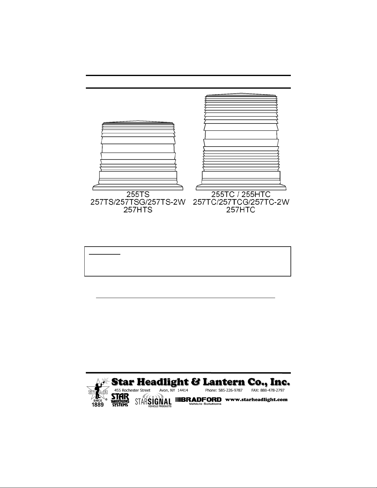
Model VDC Strobe Tube Circuit Dome Cig Plug
255TS 12-48 129 181-T-DQ 297TS-* N/A
255TSM 12 129 181-T-DQ 297TS-* 176-SW
255TC 12-48 129 181-T-DQ 295TC-* N/A
255TCM 12 129 181-T-DQ 295TC-* 176-SW
255HTC 12-24 129 181-HT-DQ 295TC-* N/A
255HTCM 12 129 181-HT-DQ 295TC-* 176-SW
257TS 12-48 129 181-T-DQ 297TS-* N/A
257TSM 12 129 181-T-DQ 297TS-* 176-SW
257TC 12-48 129 181-T-DQ 295TC-* N/A
257TCM 12 129 181-T-DQ 295TC-* 176-SW
257TSG 12-24 129 181-Q7-12 297TS-* N/A
257TCG 12-24 129 181-Q7-12 295T C-* N/A
257TS-2W 12-24 129 181-Q7-12 297TS-* N/A
257TC-2W 12-24 129 181-Q7-12 295TC-* N/A
257HTC 12-24 129 181-HT-DQ 295TC-* N/A
257HTS 12-24 129 181-HT-DQ 297T S-* N/A
PARTS
PLITSTR288 REV H 7/30/12
Page 2
Mounting
1. Your new warning light comes complete with one foam mounting gasket, one wire
grommet, two wire splicing terminals (only one with the 257TSG and 257TCG), three
mounting screws, three lock washers, and three hex nuts.
2. These warning lights come equipped with a combination base, allowing the light to be
mounted on either a 1" NPT conduit pipe or permanently mounted. For NPT pipe, mount
the light using the threaded entrance hole in the base of the light, and then skip to the
Electrical Connections below. For the permanent mount, proceed to Step 3.
3. Before installing this light onto a flat surface, it is recommended that you seal up the pipe
mount hole with a small amount of RTV. This will help prevent water damage.
4. Using the base as a template, mark three holes (on a 2.975" radius) on the mounting surface.
5. Remove the base and drill a 7/32" hole in the marked spots.
CAUTION: Take care not to drill through the headliner of the vehicle below.
6. If your wires will not be routed through the mounting surface skip to Step 8. If you are
routing your wires through the mounting surface, drill a 3/8 “ hole in the center for the wires.
7. Remove the headliner from the inside of the vehicle, if applicable. Insert the enclosed
rubber wire grommet into the center hole and route the wires through the grommet.
8. Align the outer holes of the base with the holes in the mounting surface, install the
screws and nuts, and tighten until snug. If you are installing the self-grounding
257TSG or 257TCG, be sure to scrape away the paint under the head of one of the
screws so that a good electrical connection is made.
Electrical Connections
CAUTION: All of our DC powered warning lights are polarity sensitive. These lights are
polarity protected only if the appropriate fuse is used. All wires connected to the positive
terminal of the battery should be fused at the battery for their rated load. Testing the light
before this fuse is properly installed will void the warranty on the light.
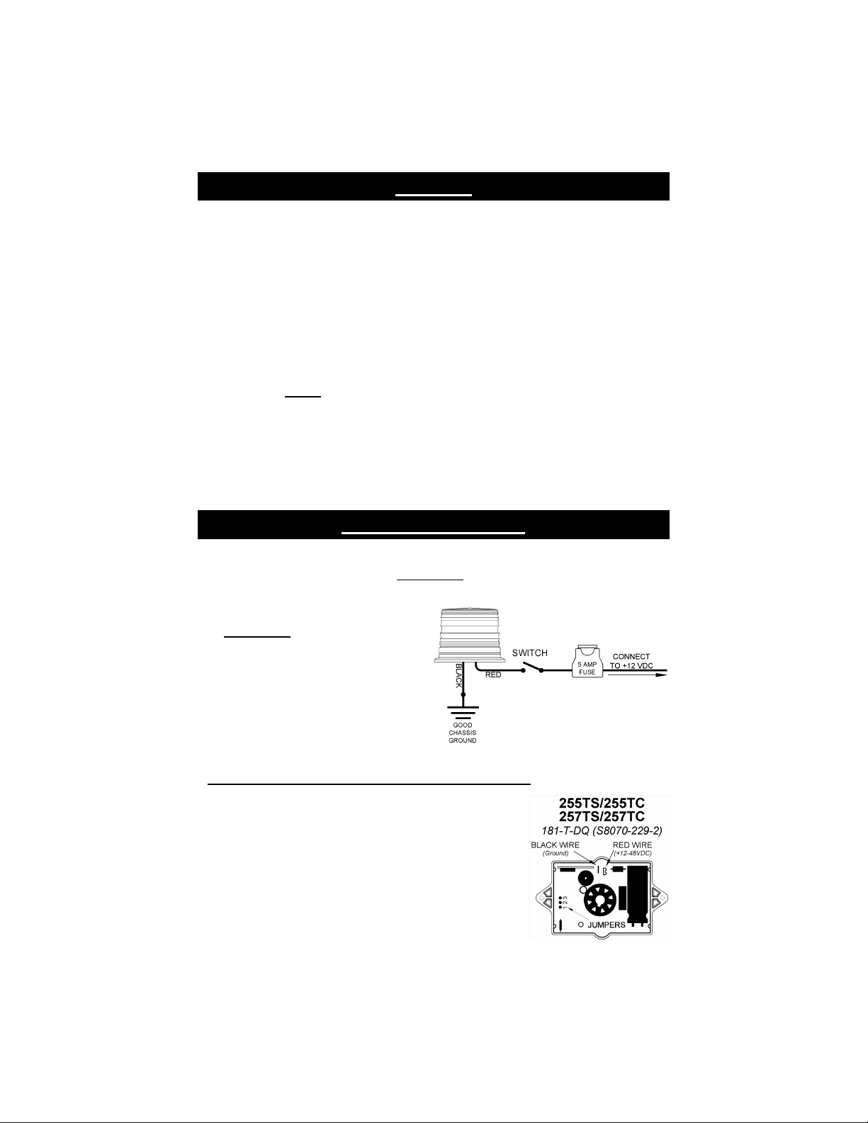
1. Connect the black wire to a good chassis
ground.
(Please note: The 257 series is self-
grounding and the black wire is
connected to the base. Be sure to
scrape away the paint under the head
of one of the mounting screws so that
a good electrical connection is made.)
2. Connect the red wire to the positive side of
your power source through a switch and a
5 Amp fuse. Be sure to check your light for
proper voltage.
255TS/255TC and 257TS/257TC Pattern Programming
Prior to shipping these models are set for quadflash mode. You
can use an internal jumper on the circuit to change the flash
pattern to singleflash or doubleflash, if desired.
1. Remove the jumper from pins 2 and 3 and briefly touch it
to pins 1 and 2 (about 1 second) and release it. The flash
pattern will advance to the next pattern.
2. Repeat touching and releasing to scroll through the patterns:
SingleflashDoubleflashQuadflash
3. Place the jumper back on pins 2 and 3 when the desired
pattern is set.
-1-
Page 3

257TSG/257TCG and 257TS-2W/257TC-2W Series Programming Options
Pattern Select
1. Remove the jumper from pins 1 & 2, momentarily
place it over pins 2 & 3, then remove it. The
pattern should advance to the next.
2. Touch and release the jumper to pins 2 & 3 to
cycle through the patterns:
SingleflashDoubleflashQuadflash
3. Once you have selected a pattern, replace the
jumper on pins 1 & 2.
High/Low Select
Use the High/Low Select Jumper to switch the
operation of the light between Low and High Power.
High Power = Jumper on Pins 1 & 2
Low Power = Jumper on Pins 2 & 3
255HTC, 257HTC, and 257HTS Features
Pattern Select
Use the Pattern Select Jumper to switch the
operation of the light between doubleflash or
Quadflash.
Quadflash = Jumper on Pins 1 & 2
Doubleflash = Jumper on Pins 2 & 3
Diagnostic LED
The LED indicator is designed to flash when
the strobe tube should be flashing. If a
strobe light is not working when power is
applied to it, but the LED is flashing, you
have a bad strobe tube. If the LED is not
flashing, the circuit is either not receiving the
proper voltage, or the circuit has failed.
Photocell
There is a built-in photocell which will
automatically switch the light to low power
during “night” (or low light) conditions
when such a high intensity is not required.
-2-
Page 4

Magnet Mount Lights
WARNING!!!! Care should be taken when positioning any warning light on the roof, dash, or
instrument panel of the vehicle, so that the light and/or cord does not interfere with the proper
operation of any airbags! Failure to heed this warning may result in serious or fatal injury.
If you are mounting the light on the roof of your vehicle, take extreme care to ensure that the magnet
is firmly seated on your roof, and that the pull of the magnet is sufficient to secure the light in place.
As the composition of the metal in the roofs of different vehicles may vary, as well as the contour,
texture and/or condition, Star cannot guarantee the ability of the light to remain in place upon a
moving vehicle. It is the sole responsibility of the owner to ensure the warning light is secure.
• CAUTION: Please be sure to check that your cigarette plug outlet is properly fused.
Testing the light before this fuse is properly installed will void the warranty on the
light.
• Once the light is secured, route your cord such that it does not interfere with the vision of
the driver or the operation of any controls, including, but not limited to, the steering
wheel, gear shifter, and/or airbag.
• This light has been factory tested and approved. If the light fails to work when the plug is
inserted into the cigarette plug socket, twist the plug a few times to remove any ash or
other deposits which might be preventing a good contact from being made. If the
problem persists, check for a fuse inside of the plug itself. If present, remove the fuse
from the circuit, check to see if it has blown, and clean the lighter socket and contact
surfaces. Reconnect the fuse and test the light again.
The manufacturer warrants each new product against factory defects in material and workmanship for one
year after the date of purchase. The owner will be responsible for returning to the Service Center any
defective item(s) with the transportation costs prepaid. The manufacturer will, without charge, repair or
replace at its option, products, or part(s), which its inspection determines to be defective. Repaired or
replacement item(s) will be returned to the purchaser with transportation costs prepaid from the service
point. A copy of the purchaser's receipt must be returned with the defective item(s) in order to qualify for the
warranty coverage. Exclusions from this w arranty include, but are not limited to, bulbs, strobe tubes, domes,
and/or the finish. This warranty shall not apply to any light, which has been altered, such that in the
manufacturer's judgment, the performance or reliability has been affected, or if any damage has resulted
from abnormal use or service.
There are no warranties expressed or implied (including any warranty of merchantability or fitness), which
extend this warranty period. The loss of use of the product, loss of time, inconvenience, commercial loss or
consequential damages, including costs of any labor, are not covered . The manufacturer reserves the right
to change the design of the product without assuming any obligation to modify any product previously
manufactured.
This warranty gives you specific l egal rights. You might also have additional rights that may vary from state to
state. Some states do not allow limitations on how long an implied warranty lasts. Some states do not allow
the exclusion or l imitation of incidental or consequential damages. Therefore, the above limitation(s) or
exclusion(s) may not apply to you.
If you have any questions concerning this or any other product,
please contact our Customer Service Department at (585) 226-9787.
If a product must be returned for any reason, please contact our Customer Service Department to
obtain a Returned Materials Authorization number (RMA #) before you ship the product back.
Please write the RMA # clearly on the package near the mailing label.
-3-
ONE YEAR LIMITED WARRANTY
 Loading...