

Page 1
250C Series
250A Series
PLITSTR42 REV. H 8/31/10
Page 2
INSTALLATION INSTRUCTIONS
1. IMPORTANT: Please read all of the following instructions before installing your new
Star warning light.
2. CAUTION: All of our DC powered warning lights are polarity sensitive. These lights
are polarity protected only if the appropriate fuse is used. All wires connected to the
positive terminal of the battery should be fused at the battery for their rated load.
Testing the li ght before this fuse is properly installed will void the warranty on
the light.
3. Your new Star warning light comes complete with a foam mounting gasket, two
mounting screws, two lock washers, and two rubber well nuts.
4. Remove the foam gasket from the shipping box. Each gasket comes furnished with
three holes, two outer and a center hole. (NOTE: You might have to stretch the
gasket to find the location of the three holes.) Place the gasket in the exact position
the light is to be mounted.
5. Using the gasket as a template, mark three holes on the mounting surface. Take care
to ensure that the gasket does not move while you are marking each of the three
holes.
6. Remove the gasket and drill a 3/8" hole in the two outer locations only.
CAUTION: Take care not to drill through the headliner of the vehicle below.
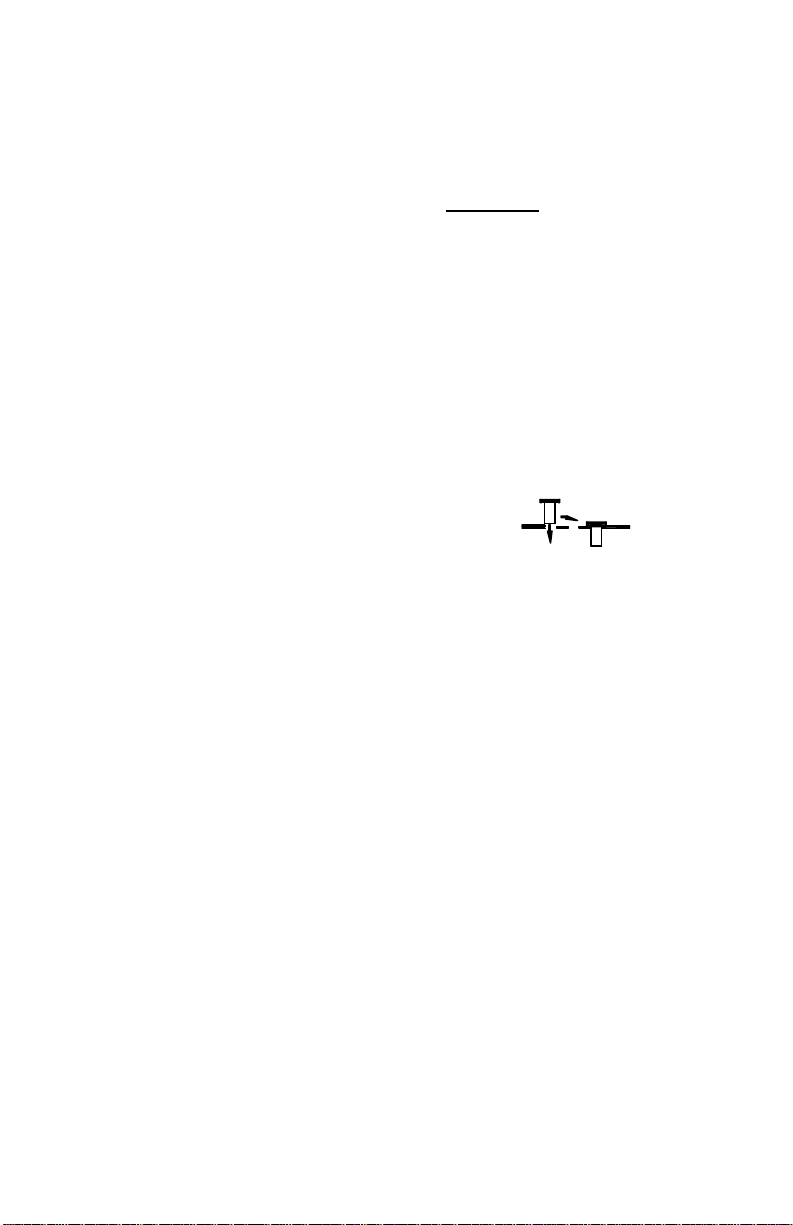
7. Push the enclosed rubber well nuts through the holes
in the vehicle until the bottom side of the wider lip rests
on the surface of the vehicle.
8. For external wiring of your new Star Strobe skip to Step 9. For internal wiring,
proceed as follows: Remove the headliner from the inside of the vehicle. Drill a 3/8"
hole in the center marked location. Route the wires through this hole.
9. Place the light on the mounting surface and align the holes in the base with the well
nuts. Install the two screws and tighten until snug.
10. The black or white wire is the ground lead and should be connected to a good chassis
ground.
11. Connect the red wire from the strobe to your switch, checking the label on the warning
light for proper voltage. Be sure to fuse your switch at the battery.
If you are installing a single flash model or a model with a photocell, you are
finished and may skip the remaining step.
If you are using the HI/LO opt ion continue to Step 12.
If you intend to operate the light on only low power, leave the purple wire
unconnected and place a wire nut on the end.
If you intend to operate the light under high power only, connect the purple wire to
your black wire which is connected to the good chassis ground (refer to the top
diagram on the next page). Skip the remaining steps.
12. If you intend to make use of the HI/LO option, refer to the wiring diagram on the
next page for proper connections using a two -switch switch panel with two single-pole,
two position switches. (This switch panel is available from Star—order part #SP38602H).
If you have any questions concerning this or any other Star product,
please contact our Customer Service Department at (585) 226-9787.
Page 3

WIRING DIAGRAM FOR STAR STROBE MODELS w/HIGH-LOW OPTION
(Red, Black, and Purple wires present)
A two-switch switch-panel is required to utilize the High/Low power option.
Make your connections as illustrated below.
SP3860-2H SWITCH PANEL (REAR VIEW)
HIGH
3
2
PURPLE
1
LOW
PURPLE
WARNING
BLACK
GOOD
CHASSIS
GROUND
LIGHT
RED
RED
ON
OFF
SW1SW2
3
2
1
10 AMP
FUSE
BLACK
CONNECT RED
FUSED LEAD TO
+12 VDC
GOOD
CHASSIS
GROUND
Special Features
(excludes S-Series single flash only and H-Series high-power lights )
Pattern Programming
The circuits now found in the 250A, 250C,
and 250S series lights have a jumper on
them allowing the end user to select the
desired flash pattern (singleflash,
doubleflash, or quadflash). If you wish to
change the pattern, activate the light and
follow the instructions below.
1. The Pattern Select Jumper
is stored on pins 1 & 2.
2. To change the pattern, remove the
jumper from pins 1 & 2, momentarily
place it over pins 2 & 3, then
remove it. The pattern should
advance to the next.
3. Continue to touch and release the jumper to pins 2 & 3 to cycle through the patterns:
4. Once you have selected a pattern, replace the jumper on pins 1 & 2.
Please Note: Some circuits may have only two pins. For those circuits, store the jumper on one of the pins, and
singleflashà doubleflashàquadflash
use the jumper on the two pins for programming.
High/Low Jumper
Mag mount models will come with a jumper that automatically defa ults the light to High
Power. To only run on Low Power, move the High/Low Select Jumper from pins 1 & 2 to
pins 2 & 3.
LED Indicator
These lights also have an LED Diagnostic Indicator. The LED indicator is designed to
flash when the strobe tube should be flashing. If a strobe light is not working,
troubleshooting becomes easy with this new LED. Simply examine the circuit when power
is applied to it. If the strobe tube is not flashing, but the LED is flashing, you have a bad
strobe tube. If the LED is not flashing, the circuit is either not receiving the proper voltage,
or the circuit has failed.
MALE TERMINAL
(FOR BLACK WIRE)
3 2 1
HIGH/LOW SELECT
JUMPERS
RED LEAD w/FEMALE TERMINAL
(FOR RED WIRE)
PATTERN SELECT
JUMPERS
3 2 1
MALE TERMINAL
(FOR PURPLE WIRE)
DIAGNOSTIC
LED
Page 4

ONE YEAR LIMITED WARRANTY
If you are mounting the light on the roof of your vehicle, take extreme care to ensure that the magnet
WARNING!!!
! Care should be taken when positioning any warning light on the roof, dash, or instrument
is firmly seated on your roof, and that the pull of the magnet is sufficient to secure the light in place.
As the composition of the metal in the roofs of different vehicles may vary, as well as the contour,
texture and/or condition, Star cannot guarantee the ability of the light to remain in place upon a
moving vehicle. It is the sole responsibility of the owner to ensure the warning light is secure.
panel of the vehicle, so that the light and/or cord does not interfere with the proper
operation of any airbags! Failure to heed this warning may result in serious or fatal
Magnet Mount Lights
• CAUTION: Please be sure to check that your cigarette plug outlet is properly fused.
Testing the light before this fuse is properly installed will void the warranty on
the light.
• Once the light is secured, route your cord such that it does not interfere with the
vision of the driver or the operation of any controls, including, but not limited to, the
steering wheel, gear shifter, and/or airbag.
• This light has been factory tested and approved. If the light fails to work when the
plug is inserted into the cigarette plug socket, twist the plug a few times to remove
any ash or other deposits which might be preventing a good contact from being
made. If the problem persists, check for a fuse inside of the plug itself. If present,
remove the fuse from the circuit, check to see if it has blown, and clean the lighter
socket and contact surfaces. Reconnect the fuse and test the light again.
The manufacturer warrants each new product, under normal use, against factory defects in material and
workmanship for one year after the date of purchase. The owner will be responsible for returning to the
Service Center any defective item(s) with the transportation costs prepaid. The manufacturer will, without
charge, repair or replace at its option, products, or part(s), which its inspection determines to be defective.
Repaired or replacement item(s) will be returned to the purchaser with transportation costs prepaid from the
service point. A copy of the purchaser's receipt must be returned with the defective item(s) in order to
qualify for the warranty coverage.
Exclusions from this warranty include, bu t are not limited to, bulbs, strobe tubes, domes, and/or the finish. This
warranty shall not apply to any light, which has been altered, such that in the manufacturer's judgment, the
performance or reliability has been affected, or if any damage has resulted from abnormal use or service.
This warranty does not apply to defect or damage occurring as a result of disaster, accident, abuse, misuse,
lightning, power surges, or failure to follow instructions in any enclosed manuals. Any damage or defects
occurring as a result of any unauthorized service or repairs by unauthorized persons shall be excluded from
this warranty.
There are no warranties expressed or implied (including any warranty of merchantability or fitness), which
extend this warranty period. The loss of use of the product, loss of time, inconvenience, commercial loss, or
consequential damages, including costs of any labor, are not covered. The manufacturer reserves the right
to change the design of the product without assuming any obligation to modify any product previously
manufactured.
This warranty gives you specific legal rights. You might also have additional rights that may vary from state to
state. Some states do not allow limitations on how long an implied warranty lasts. Some st ates do not allow
the exclusion or limitation of incidental or consequential damages. Therefore, the above limitation(s) or
exclusion(s) may not apply to you.
If you have any questions concerning this or any other Star product,
please contact our Customer Service Department at (585) 226 -9787.
If a product must be returned for any reason, please contact our Customer Service Department
to obtain a Returned Materials Authorization number (RMA #) before you ship the product to Star.
Please write the RMA # clearly on the package near the mailing label.
 Loading...