

Page 1

INSTALLATION AND INSTRUCTION MANUAL
Models
Models
ModelsModels
2364LED, 2464LED and 2564LED
®
Plus Lightbars
PLIT429 REV. D 11/11/13
Page 2
!
When mounting your lightbar, please be sure to keep any radio frequency
sensitive equipment at least 20” from the bar and power cable(s). This is
especially critical in lightbars utilizing strobes. Our strobe power supplies
have been designed to limit RFI emissions, but certain very sensitive
equipment may still be affected. Symptoms may include, but are not
limited to, sporadic operation and degraded performance. Star Headlight
& Lantern Co., Inc. cannot assume any responsibility for any radio
frequency induced malfunction or damage to any radios, sirens, lightbars,
or any other equipment mounted within 20” of a strobe lightbar. Any
antennae mounted in the proximity of the lightbar may cause your radio to
suffer the aforementioned results.
PLEASE NOTE: THE DIRECT MOUNT IS THE STANDARD
MOUNT INCLUDED WITH THE LIGHTBAR.
THE HOOK MOUNTS MUST BE USED ON ALL POLICE AND/
OR OTHER EMERGENCY VEHICLES!!!
THE HOOK MOUNTS ARE SOLD SEPARATELY. THEY ARE
NOT INCLUDED WITH EACH LIGHTBAR. THEY MUST BE
ORDERED SEPARATELY. SEE THE ACCOMPANYING
HOOK MOUNT MANUAL FOR A COMPLETE LIST OF
AVAILABLE MOUNTS AND KNOWN VEHICLE
APPLICATIONS.
I
t is the sole responsibility of the owner to ensure the lightbar is
mounted securely. Check your light every time you enter the
vehicle to ensure that it is mounted securely. The manufacturer
assumes no responsibility for the secure mounting of this light.
This light uses state-of-the-art Light Emitting Diode (LED) technology. This warning
light is comprised of ultra-high intensity LEDs that are operated by a micro-controller
to efficiently produce light output with lifetimes up to 100,000 hours.
-i-
Page 3

Please Note: These instructions are provided as a general guideline only. Specific
mounting, wiring, and/or weather-sealing may be necessary and are the sole
responsibility of the installer. Star Headlight & Lantern Co., Inc. assumes no
responsibility for the integrity of the installation for this or any of its products.
Table of Contents
WARNINGS i
QUICK-INSTALL WIRING GUIDE 1-2
MOUNTING INSTRUCTIONS 3
(For Mounting see Mounting Bracket Manual)
WIRING INSTRUCTIONS 3-6
Direct Wiring Guide 3-4
Electrical Connections 5
Wire Functions 6
PATTERN PROGRAMMING 7-9
Flash Patterns 8
Synchronization 9
TROUBLESHOOTING 9
PARTS 10-11
SWITCHES 12
WARRANTY 13
SERVICE 13
Due to continuous product improvements, we must reserve the right to change any specifications and information,
contained in this manual at any time without notice. Star Headlight & Lantern Co., Inc. makes no warranty of any
kind with regard to this manual, including, but not limited to, the implied warranties of merchantability and fitness
for a particular purpose. Star Headlight & Lantern Co., Inc. shall not be liable for errors contained herein or for
incidental or consequential damages in connection with the furnishing, performance, or use of this manual.
-ii-
NOTICE
Page 4
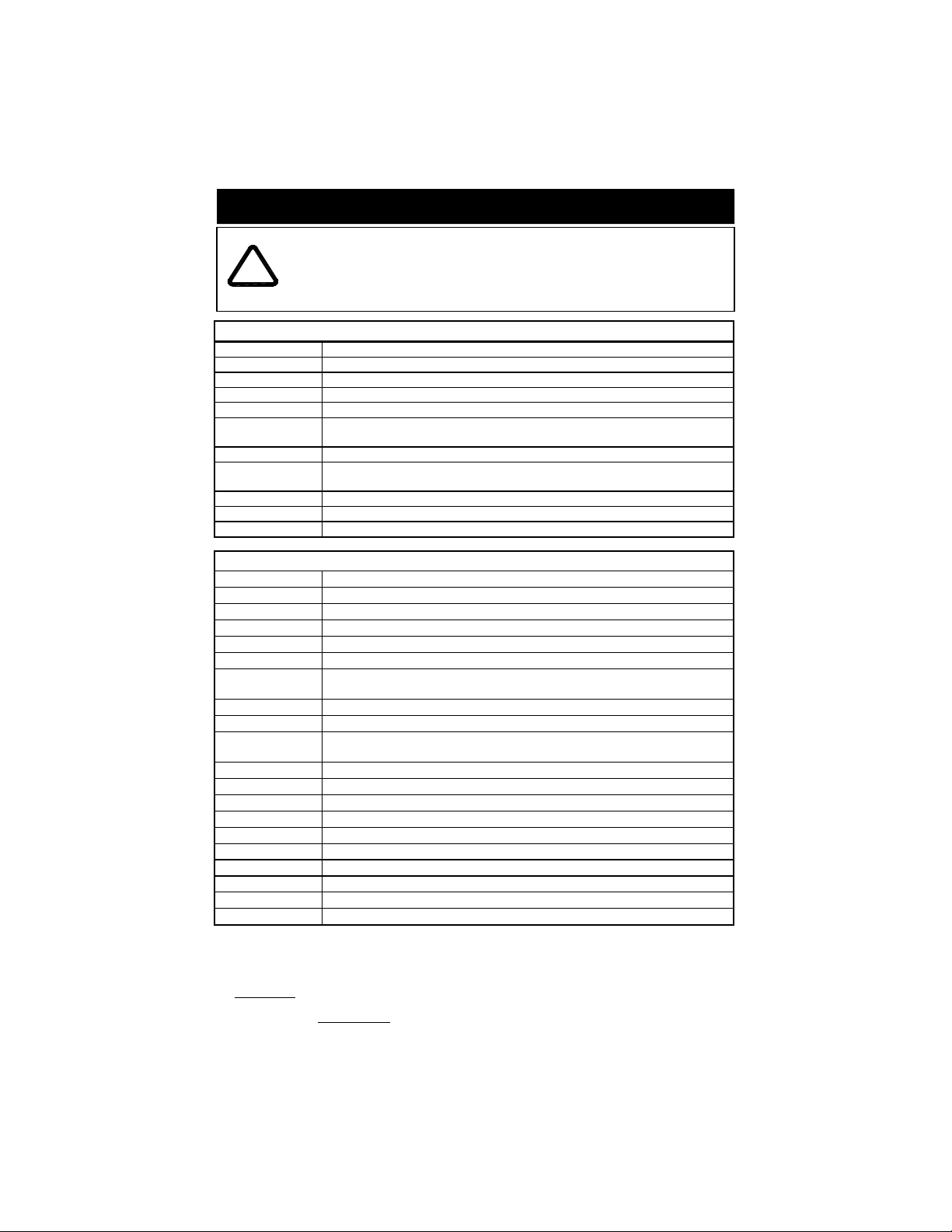
QUICK-INSTALL WIRING GUIDE
WIRE COLORS AND FUNCTIONS WILL VARY FROM HARNESS TO
HARNESS. PLEASE BE SURE TO CORRECTLY IDENTIFY YOUR
HARNESS AND USE THE CORRESPONDING TABLE. IN ADDITION, ALL
!
LIGHTBARS ARE SHIPPED WITH A WORKSHEET THAT IDENTIFIES THE
FUNCTION FOR EACH WIRE COLOR IN THAT SPECIFIC LIGHTBAR.
11-Wire Harness
Green w/Yellow Driver Side Scene Lights
White w/Brown Passenger Side Scene Lights
Brown Rear Enable (Turns on Rear Facing M-Tech Plus™ Lights)
Orange Front Enable (Turns on Front Facing M-Tech Plus™ Lights)
White Synchronization (Used to synchronize two or more lights together)
Green
Purple High/Low Select (Optional - Ground for low intensity)
Red w/Green
Red
Black Ground (Connect to the negative side of the battery)
Bare Ground (Shield - Connect to a good chassis ground)
Passenger Side Pattern Select (Touch and release to +12-24 VDC to
change patterns)
Driver Side Pattern Select (Touch and release to +12-24 VDC to change
patterns)
Power (Connect to constant +12-24 VDC †)
20-Wire Harness Wiring
Blue Driver Side Alley Light (Switched +12VDC Only)
White w/Blue ICL Power (Intersection Clearing Lights) or Scene Lights
White w/Yellow Front Corner (Controls any lights in the front corners other than ICL)
Orange w/Yellow
Brown w/Yellow Not Used or Optional Component
Red
Red w/Green
Purple Optional - High/Low (Ground for low intensity)
Green w/Yellow Front Center (Controls any lights in the front centers)
Red/Black
White w/Brown Alt. Front Center (Controls any alternate lights in the front centers)
Green w/Red Rear Center (Controls any lights in the rear centers)
Brown w/Red Not Used or Optional Component
Orange w/Red Rear Enable (Turns on Rear Facing M-Tech Plus™ Lights)
White w/Red Synchronization (Used to synchronize two or more lights together)
Yellow w/Black Alt. LED 1 (Controls any alternate LED lights)
White w/Black Alt. LED 2 (Controls any additional alternate LED lights)
Gray
Black Ground (Connect to the negative side of the battery)
Bare Ground (Shield - Connect to a good chassis ground)
† -
The Red wire MUST be connected to +12VDC for the front and rear warning LEDs to operate. If you
are NOT utilizing a separate Front and Rear enable function, you may connect the Red wire, along with
the Front enable wire and Rear Enable wire to +12-24VDC through your On/Off switch.
If you ARE using a separate Front and Rear Enable function, connect this wire to constant +12-24VDC.
Please note: When the red POWER wire is connected to constant power the light will draw a small
current (20 mA). If your vehicle will be sitting for extended periods of time (i.e. more than a few days), it
is recommended all power wires be routed through an ignition switched power source.
Front Enable (Turns on Front Facing M-Tech Plus™ Lights)
Power (Connect to constant +12-24 VDC †)
Passenger Side Pattern Select (Touch and release to +12-24 VDC to
change patterns)
Driver Side Pattern Select (Touch and release to +12-24 VDC to
change patterns)
Passenger Alley (Switched +12VDC Only)
(271-PHANTOM)
(271RAZOR)
-1-
Page 5
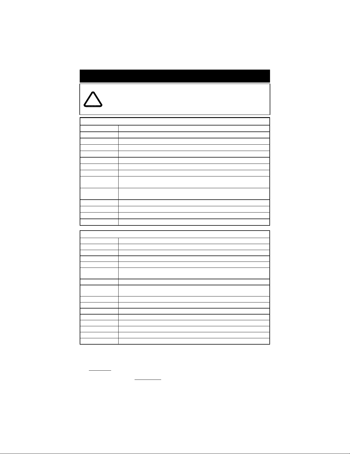
QUICK-INSTALL WIRING GUIDE
WIRE COLORS AND FUNCTIONS WILL VARY FROM HARNESS TO
HARNESS. PLEASE BE SURE TO CORRECTLY IDENTIFY YOUR
HARNESS AND USE THE CORRESPONDING TABLE. IN ADDITION, ALL
!
LIGHTBARS ARE SHIPPED WITH A WORKSHEET THAT IDENTIFIES THE
FUNCTION FOR EACH WIRE COLOR IN THAT SPECIFIC LIGHTBAR.
14-Wire Harness Wiring
Light Blue Optional - High/Low (Ground for low intensity)
Orange Rear Enable (Turns on Rear Facing M-Tech Plus™ Lights)
Yellow Left Stop (+12VDC Only - Used only if you have STT lights in your bar)
Green Right Stop (+12VDC Only - Used only if you have STT lights in your bar)
White w/Orange Work Lights (+12VDC Only - Used only if you have worklights in your bar)
Brown Tail (+12VDC Only - Used only if I.D. or STT lights are in your bar)
Red
Red w/White
Red w/Green
Black w/Green
White w/Green Front Enable (Turns on Front Facing M-Tech Plus™ Lights)
Gray Synchronization (Used to synchronize two or more lights together)
Black Ground (Connect to the negative side of the battery)
Bare Ground (Shield - Connect to a good chassis ground)
Power (Connect to constant +12-24 VDC †)
Scene Lights
Passenger Side Pattern Select (Touch and release to +12-24 VDC to
change patterns)
Driver Side Pattern Select (Touch and release to +12-24 VDC to
change patterns)
16-Wire Harness Wiring
Light Blue Driver Side Alley Light (Switched +12VDC Only)
White w/Brown Pursuit (Used only if Pursuit lights are in your bar)
White w/Blue ICL Power (Intersection Clearing Lights)
Green w/Yellow Takedowns (Used only if Takedown lights are in your bar)
Red
Red w/Black
Red w/White Synchronization (Used to synchronize two or more lights together)
Red w/Green
Black w/Green Rear Enable (Turns on Rear Facing M-Tech Plus™ Lights)
White w/Green Front Enable (Turns on Front Facing M-Tech Plus™ Lights)
Orange Not Used or Optional Component
White Rear Flashers (Used only if Rear Flashers are in your bar)
Orange w/Red Optional - High/Low (Ground for low intensity)
Gray
Black Ground (Connect to the negative side of the battery)
Bare Ground (Shield - Connect to a good chassis ground)
† -
The Red wire MUST be connected to +12VDC for the front and rear warning LEDs to operate. If you
are NOT utilizing a separate Front and Rear enable function, you may connect the Red wire, along
with the Front enable wire and Rear Enable wire to +12-24VDC through your On/Off switch. If you
ARE using a separate Front and Rear Enable function, connect the Red wire to constant +12-24VDC.
Please note: When the red POWER wire is connected to constant power the light will draw a small
current (20 mA). If your vehicle will be sitting for extended periods of time (i.e. more than a few
days), it is recommended all power wires be routed through an ignition switched power source.
Power (Connect to constant +12-24 VDC †)
Driver Side Pattern Select (Touch and release to +12-24 VDC to
change patterns)
Passenger Side Pattern Select (Touch and release to +12-24 VDC to
change patterns)
Passenger Alley (Switched +12VDC Only)
(271-TOWBAR)
(271-STROBE)
-2-
Page 6

Mounting Instructions
Please review the separate Mounting Bracket manual that
is also enclosed with your bar for mounting instructions.
Wiring Harness Replacement
All standard lightbar models are designed for 12VDC negative ground vehicles
only. Reverse polarity will cause serious damage to the lightbar and/or vehicle.
Contact the automotive dealer if there are any doubts about the polarity of your vehicle.
PLEASE NOTE: If you are using the existing wire harness supplied with the lightbar,
Standard Razor lightbars come with a 15-foot wiring harness. If the harness supplied with
the lightbar is not long enough for your application, Star recommends ordering the proper
cable of the desired length from the factory. Completely remove the pre-installed wire
harness and replace it with one that is the correct length.
•
Star recommends direct wiring to the terminal block on the inside of the lightbar,
rather than making connections to the end of the wire that is supplied.
•
This lightbar is designed so that when replacing the wire harness, no wire
connectors are needed and only a few common tools are necessary.
•
Direct wiring allows the wire connections to the lightbar to be made in a clean and
dry environment, avoiding any problems that may arise due to weathering on
external connections.
•
Wiring directly inside the lightbar reduces the number of connections. There is an
increase in voltage loss with the addition of each connection.
•
Making connections to the wires already provided is an acceptable alternative, as
long as these connections are good electrical connections and are resistant from
weathering effects.
1. Determine the number of wires that you will need to run. Your lightbar may not use all of
the wires in the harness that was shipped with the lightbar. Please note which functions
your bar has, then review the lists on pages 1-2 to determine which wires you will need
to connect. The bare drain wire in our harness is optional (but recommended) and is
only necessary if you are experiencing RFI problems.
2. Locate the end of the lightbar into which the wire harness runs.
The black terminal block(s), which you will be
making your wire terminations to, should also be
located at this same end.
3. Remove the dome lens at this end of the
lightbar:
Step A: Loosen the four screws holding
Step B: Lift the dome off of the base
Step C: When all work is completed,
each dome on.
exposing the interior components.
reverse the steps to reinstall the
dome, taking care that the gasket
is properly aligned.
-3-
Page 7

(Direct Wiring Guide CONT’D)
4. The wiring harness will connect to one or more terminal blocks inside the lightbar. All of
the wires coming from the harness are terminated on one side of the terminal block and
the wires leading to the internal components terminate on the opposite side of the
terminal block. The Wiring Guide on pages 1-2 lists the wire colors from the harness in
the same order as they are connected to the terminal block(s). Using the Wiring Guide,
note which end of the terminal block(s) the wires in your harness start from.
5. Loosen the screws on the HARNESS SIDE of the terminal block and remove the harness.
Remember that there may be “dead” wires from the harness connected to the terminal
block inside your lightbar, but there will be no wires connected to the terminal across from
them. These are extra wires in the harness that are not used. Replacing these wires in
your new harness is not necessary.
6. Run the new external wires up through the wire bushing into the base and to the terminal
block(s). Use the Wiring Guide to help determine where each of your new wires should
be connected.
7. Strip each wire 1/4". Connect the external wires to the proper poles of the terminal block
by inserting the stripped portion of the wire under the rising clamp screw and tightening
down the screw. Note that no wire terminals are needed for connecting wires to this
terminal block.
Be sure to check that no strands of wire are loose and shorting to the
adjacent terminal or to the base of the lightbar.
All switches used should be rated for at least 125% of their rated load.
Please note that your lightbar may have more or fewer
wires in the harness or from the lightbar, and it may or
may not use terminal jumpers as pictured below.
From Lightbar Components
These
Remove
From Wire Harness
BLACK
-4-
Page 8

Electrical Connections
All standard lightbar models are designed for 12VDC negative ground vehicles
only. Reverse polarity will cause serious damage to the lightbar and/or vehicle.
Contact the automotive dealer if there are any doubts about the polarity of your vehicle.
RF INTERFERENCE
Please take the following steps to help eliminate any Radio Frequency Interference (RFI)
with your two-way radio.
• DO NOT run the power wire for the lightbar along same path as any antenna wires.
• DO NOT run the power wire for the lightbar along same path as any radio power wires.
• DO NOT tap power for the lightbar off of the radio power wires.
• DO NOT mount the lightbar within 20” of any antennae. Sometimes mounting the
lightbar or antenna over by just one foot can make a large difference in the
interference.
• Ensure the black wire from the lightbar has a good connection to the negative side of
the battery.
• For all standard Razor lightbars, 15 feet of cable (plus a drain wire and a foil shield) is
supplied with the bar. All wires are color coded and sized at the correct gauge. If this
length is not sufficient, it is recommended that the wire harness be completely replaced
with the only connections to be made directly at the terminal block inside the lightbar.
This will reduce the number of wire connections and help prevent any weathering
problems on these connections. Refer to the Direct Wiring Guide on pages 3-4 for
further instructions on this.
• CAUTION: All wires and switches should be rated for at least 125% of their
maximum current load. In addition, all wires connected to the positive terminal of the
battery should be fused at the battery for 125% of their rated load. The load can be
calculated by adding all lamp wattages and dividing by 13. (Load <Amps> = Total
Watts / 13 volts) Do not use 1/4" diameter glass fuses, as they are not suitable for
continuous duty above 20 amps. If you are unsure of the current draw, please contact
our Customer Service Department.
• TESTING THE LIGHTBAR BEFORE IT IS PROPERLY FUSED & INSTALLED WILL
VOID THE WARRANTY!!
• The black ground wire should be connected to the negative terminal of your vehicle’s
battery. This wire should be as short as possible in order to minimize the voltage loss
in this wire and reduce any chance of overheating.
• Your harness will contain all of the colored wires in its corresponding harness. Most
applications though, will not use every wire. The “dead” wires in the harness will be
connected to the terminal block inside your lightbar, but there will be no wires
connected to the terminal across from them. These “dead” wires can be used for
additional components that may be added at some point in the future, or they may be
used to separately switch components that are currently wired together.
• Since many of the lightbars we build have custom components, and numerous different
harnesses are used, wire colors WILL vary. You can use the Wire Guide on pages 1-2
or the worksheet shipped with each bar to identify the function of each wire If you are
still unsure of the function of a particular wire, you may test the function by grounding
the black wire and applying +12VDC to the wire in question. Be sure to use a 20-amp
fuse when testing.
-5-
Page 9

Wire Functions
WIRE COLORS AND FUNCTIONS WILL VARY FROM HARNESS TO HARNESS.
PLEASE BE SURE TO CORRECTLY IDENTIFY YOUR HARNESS AND USE THE
CORRESPONDING TABLE IN THE WIRING GUIDE ON PAGES 1-2. IN ADDITION,
ALL LIGHTBARS ARE SHIPPED WITH A WORKSHEET THAT IDENTIFIES THE
!
FUNCTION FOR EACH WIRE COLOR IN THAT SPECIFIC LIGHTBAR.
Ground - Connect to the negative side of the battery.
Bare/Shield - Connect to the negative side of the battery.
Power (Red) - Connect to +12-24 VDC through your switch. Be sure to use a 10 amp fuse
when connecting the switch to the positive side of the power supply.
The Red wire MUST be connected to +12VDC for the front and rear M-Tech
Plus™ LEDs to operate.
Please note: When the red POWER wire is connected to constant power the
light will draw a small current (20 mA). If your vehicle will be sitting
for extended periods of time (i.e. more than a few days), it is
recommended all power wires be routed through an ignition
switched power source.
Front Enable - When the red POWER wire has power to it, applying +12VDC to the Front
Enable wire will switch the front M-Tech Plus™ lights on independently from the
Rear Enable - When the red POWER wire has power to it, applying +12VDC to the Rear
rear M-Tech Plus™ lights.
Enable wire will switch the rear M-Tech Plus™ lights on independently from the
front M-Tech Plus™ lights.
If you do not need independent control of the front and rear M-Tech
Plus™ lights, it is recommended that you connect all THREE wires
(Power, Front Enable, and Rear Enable) together through your switch.
Driver Side Pattern Select - Touch and release to +12-24 VDC to change the flash pattern
on the Driver side M-Tech Plus™ array (see page 7).
Passenger Side Pattern Select - Touch and release to +12-24 VDC to change the flash pattern
on the Passenger side M-Tech Plus™ array (see page 7).
High/Low - Used for switching between High and Low power.
• Leave disconnected for High Power only (cover with wirenut or tape).
• Connect to Ground for Low Power only.
Synchronization - Using this wire, two or more M-Tech Plus™ circuits or lights can
• Connect to Ground through a switch for High/Low switching.
be synchronized with one another. If you will be synchronizing two or more
units together, or synchronizing this light with other approved synchronizable
lights, leave the White/Red wire disconnected for now. Connect the White/
Red wires from all units together ONLY AFTER PROGRAMMING them for
the same pattern (see Pattern Programming on page 7).
Additional components - If your bar contains any additional components including, but not
limited to, those listed below, applying +12VDC to the appropriate
wire will activate those components:
•
Driver Alley
•
Passenger Alley
•
Intersection Clearing Lights
•
Takedown Lights
•
Pursuit Lights
•
Rear Flashers
•
Work Lights
•
Right Stop Lights
•
Left Stop Lights
•
Tail Lights
•
Scene Lights
•
I.D. Lights
•
Additional LED Lights
•
Additional Strobe Lights
•
Additional Rotating Lights
-6-
Page 10

Pattern Programming
Before changing the pattern, please review these key points about programming the lightbar:
• The lightbar consists of two separate circuits. One circuit controls the driver's side and the
other circuit controls the passenger's side.
• The driver's side circuit and passenger's side circuit are programmed with different wires.
The colors will vary depending upon your harness. Review the chart on pages 1-2 that
corresponds to your harness to identify the color of each of the programming wires.
• The two sides are usually programmed at the same time by connecting the two pattern
programming wires together. The only exception typically will be when you wish to set the
two sides for patterns that differ from one another.
• The default pattern for this lightbar will produce a Quadflash with Post Pop pattern that
alternates between the two halves of both the passenger side and driver side.
1. Connect both the Driver Side and Passenger Side Pattern Select wires together.
2. Power up the light so that it is flashing.
3. Touch and hold the Pattern Select Wires to +12-24VDC for 3 seconds. After 3 seconds, the
light should blink once and you should release the Pattern Select wires. This will set both
circuits to Pattern 1 (Alternating Flicker).
4. Touch the Pattern Select wires to +12-24VDC for one second and release them to scroll
through the patterns listed on the following page. The cycle will repeat itself after the last
pattern.
5. Once you find the pattern you wish to display, connect the Pattern Select wires to
ground and deactivate the light. This will store the selected pattern.
Programming Shortcuts
For quicker programming, you can skip directly to specific patterns in the programming
sequence. Touch and hold the Pattern Select wires to +12/24VDC for the length of
time that corresponds to the pattern you would like to jump to. Then release the
Pattern Select wires once the light blinks the appropriate number of times.
Length of Hold Unit Blinks Jumps to
3 seconds
6 seconds
9 seconds
12 seconds
15 seconds
If you wish to set the lightbar back to the factory default pattern(s), proceed below:
1. Follow Steps 1-2 above.
1 time
2 times
3 times
4 times
5 times
† -
Pattern 1
†† -
Pattern 6
††† -
Pattern 11 or 13
†††† -
Pattern 16
††††† -
Pattern 26
Restoring the Factory Default Pattern(s)
2. Instead of holding both Pattern Select wires to +12-24VDC for three seconds, as
indicated in Step 3 above, hold them to +12-24VDC for 6 seconds.
3. After 6 seconds, the light will blink twice.
4. Release the Pattern Select wires and both circuits will be programmed for Pattern 6
(Alternating Quadflash).
5. Touch the Pattern Select wires to +12-24VDC for one second and release them. This
will advance the circuits to Pattern 7 (Alternating Quadflash with Post Pop).
6. Connect the Pattern Select wires to ground and deactivate the light. This will store the
selected pattern(s).
-7-
Page 11

Flash Patterns
Flash
Pattern #
1 Alternating Flicker 1.0
2 Alternating Fast Double Flash 3.3
3 Alternating Triple Flash 2.5
4 Alternating PSU Flicker 0.7
5 Alternating PSU Random 0.6
6 Alternating Quad Flash 1.0
7 Alternating Quad Flash w/Post-Pop 1.0
8 Alternating Single Flash 1.0
9 Alternating Slow Double Flash 1.0
10 Alternating Variable 0.3
Alternating Post Pop (Amber Value versions)
11
Alternating Quintflash (All others)
Alternating Random (Amber Value versions)
12
Swing (All others)
Alternating Quintflash (Amber Value versions)
13
Alternating Fast Doubleflash, Alternating Flicker (All others)
Alternating Fast Doubleflash, Alternating Flicker
14
Alt. Quad, Alt. Flicker, Alt. Double, Flicker (All others)
Alt. Quad, Alt. Flicker, Alt. Double, Flicker
15
Counter Clockwise Rotation (All others)
16 Simultaneous Quad w/Post Pop (Phase 1) 1.0
17 Simultaneous Quad w/Post Pop (Phase 2) 1.0
18 Alt. Triple, Alt. Non-Synch Double, Alt. Quint, Flicker N/A
19 Steady burn one side, Other side Single Flash 1.0
20 Cycle All N/A
21 ☼ Quad w/Post Pop, Fast Double w/Post Pop ☼
22 ☼ Alternating Non-Synch Double ☼
23 ☼ Swing, Fli cker ☼
24 ☼ Slow Doubl e, Fast Double ☼
25 ☼ Alternating Fade ☼
26 ☼ Simultaneous Flicker (Phase 1) ☼
27 ☼ Simultaneous Flicker (Phase 2) ☼
28 ☼ Simultaneous Tripleflash (Phase 1 ☼)
29 ☼ Simultaneous Tripleflash (Phase 2) ☼
30 ☼ Simultaneous Doubleflash (Phase 1) ☼
31 ☼ Simultaneous Doubleflash (Phase 2) ☼
32 ☼ Simultaneous Quadflash (Phase 1) ☼
33 ☼ Simultaneous Quadflash (Phase 2) ☼
Sim. Quad (Phase 1), Alt. Triple,
34 ☼
Sim. Flicker (Phase 1), Alt. Fast Double ☼
Sim. Quad (Phase 2), Alt. Triple,
35 ☼
Sim. Flicker (Phase 2), Alt. Fast Double ☼
†, ††, †††, ††††, ††††† = Programming Shortcuts 1, 2, 3, 4, and 5 (see table on previous page)
* = Used for Synchronization
** = Cycles Per Second
Pattern Description CPS** Shortcut
†
3Sec
††
6Sec
†††
9Sec
†††
9Sec
(FOR AMBER VERSIONS)
††††
12Sec
†††††
15Sec
(Amber Value versions)
(Amber Value versions)
1.2
(FOR NON-AMBER VERSIONS)
1.3
N/A
N/A
2.5
N/A
3.4
N/A
N/A
0.8
1.0
1.0
2.5
2.5
1.0
1.0
1.0
1.0
N/A
N/A
The S8070-346-2**circuit, used in these lightbars, has low input voltage detection. With this feature the
lightbar senses the input voltage and flashes a fast pattern (approximately 16 cycles per second) to indicate
to the user that the battery voltage in getting low (less than 10V). Once the input voltage returns to normal
(greater than 12V) the unit will return to the normal flashing.
☼
Patterns 21-35 are NOT included in the Amber Value versions
-8-
Page 12

Synchronization
You can synchronize up to six total approved lights.
If you will be synchronizing your light with any of our products, please note the
following:
• All units that are to be synchronized MUST have the same Pattern.
• To check pattern compatibility with other products, review the Pattern List for
each product, noting the Pattern. Certain patterns are compatible with some lights, but not
compatible with others.
• Programmable Flash Patterns can vary between our different lights, but Patterns 6-10 are
fully compatible patterns with ALL of our other products.
• Program the Pattern(s) for each light PRIOR TO connecting the synchronization
wires together.
• All Synchronized Units must be switched ON/OFF by the same power switch.
Troubleshooting
Symptom Possible solutions
Flash Pattern is not changing Pattern select wire must be pulled to +12VDC to
Unit stuck in high power High/Low wire must be grounded to activate
Bar is not synchronizing with
other product
One single LED is out. The entire flasher board will need to be
One complete half of the bar is
out.
If the bar is experiencing erratic
flashing or side to side
synchronizing within the bar is
not working.
change pattern.
low power mode.
-Check to ensure all desired lights to be
synchronized have the capability of being
synchronized.
-Check to ensure synchronization wire is
connected to all units that are desired to be
synchronized.
-Check to ensure all lights to be synchronized
are set to same Pattern.
-Ensure that the entire system that is desired to
be synchronized is powered up at the same
time via the same switch.
-Ensure that the total amount of synchronizable
products in the system does not exceed 6 lights.
replaced.
-Check wiring to the flasher board that is
experiencing the problem.
-The entire LED board on that side may need to
be replaced.
-Ensure both sides are set to the same Pattern
Type.
-Ensure synchronization wire is connected
between both flasher boards internally.
-Ensure both flasher circuits in the bar are
powered from the same power switch.
-9-
Page 13

Parts
Please note that these items are not drawn to scale. Many have been enlarged to show
more detail.
-10-
Page 14

(Parts CONT’D)
*=COLOR
Please note that these items are not drawn to scale.
-11-
Page 15

Optional Switch Boxes
SP3860-1 SP3860-4
SP3860-2 SP3860-3
SP1515 SB1515
ROTATORS
ROTATORS
STROBES
SP3015
LEFT
STROBES
RIGHT
ALLEY
ALLEY
SB4020
LEFT
RIGHT
ALLEY
ALLEY
SB4020T
WORK
LIGHTS
WORK
LIGHTS
FLASHERS
FLASHERS
-12-
SB3015
GRILL
MODE
1 2 3
LIGHTS
SB4040
SB4425
HEADLIGHT
FLASHER
CORNER
LIGHTS
TAKE
DOWN
Page 16

Warranty
ONE YEAR LIMITED WARRANTY
The manufacturer warrants each new product, under normal use, against factory defects in material
and workmanship for one year after the date of purchase. The manufacturer warrants the LED
components in this light against factory defects in material and workmanship for five years after the
date of purchase. The owner will be responsible for returning to the Service Center any defective
item(s) with the transportation costs prepaid. The manufacturer will, without charge , repair or
replace at its option, products, or part(s), which its inspection determines to be defective. Repaired
or replacement item(s) will be returned to the purchaser with transportation costs prepaid from the
service point. A copy of the purchaser's receipt must be returned with the defective item(s) in order
to qualify for the warranty coverage. If a copy of the receipt is not provided, the warranty period
shall cover five years from the date of manufacture.
Exclusions from this warranty include, but are not limited to, bulbs, strobe tubes, domes, and/or the
finish. This warranty shall not apply to any light, which has been altered, such th at in the
manufacturer's judgment, the performance or reliability has been affected, or if any damage has
resulted from abnormal use or service. This warranty does not apply to defect or damage occurring
as a result of disaster, acciden t, abuse, misuse, lightning, power surges, or failure to follow instructions
in any enclosed manuals. Any damage or defects occurring as a result of any unauthorized service
or repairs by unauthorized persons shall be excluded from this warranty.
There are n o warranties expressed or implied (including any warranty of merchantability or fitness),
which extend these warranty period. The loss of use of the product, loss of time, inconvenience,
commercial loss or consequential damages, including costs of any labor, are not covered. The
manufacturer reserves the right to change the design of the product without assuming any
obligation to modify any product previously manufactured.
This warranty gives you specific legal rights. Y ou might also have additional rights that may vary from
state to state. Some states do not allow limitations on how long an implied warranty lasts. Some
states do not allow the exclusion or limitation of incidental or consequential damages. Therefore,
the above limitation(s) or exclusion(s) may not apply to you.
LED FIVE YEAR LIMITED WARRANTY
If you have any questions concerning this or any other product, please contact our
Customer Service Department at (585) 226-9787.
If a product must be returned for any reason, please contact our
Customer Service Department to obtain a Returned Materials Authorization
Number (RMA #) before you ship the product back.
Please write the RMA # clearly on the package near the mailing label.
-13-
 Loading...