

Page 1
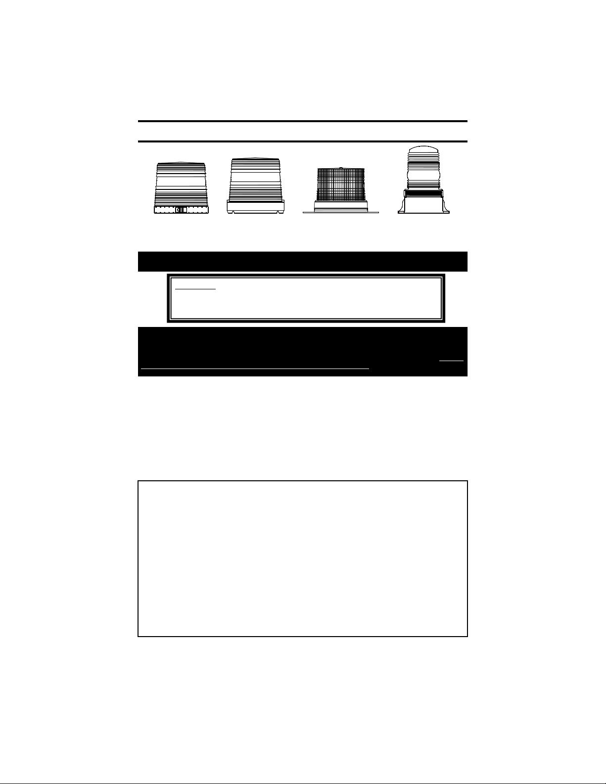
INSTALLATION AND INSTRUCTION MANUAL
200ZL
SERIES
201ZL
SERIES
203MVL
SERIES
204MVL
SERIES
Magnet Mounting
WARNING!!!! Care should be taken when positioning any warning light on the roof,
If you are mounting the light on the roof of your vehicle, take extreme care to ensure that the magnet is
firmly seated on your roof, and that the pull of the magnet is sufficient to secure the light in place. As the
composition of the metal in the roofs of different vehicles may vary, as well as the contour, texture and/or
condition, Star cannot guarantee the ability of the light to remain in place upon a moving vehicle. It is the
sole responsibility of the owner to ensure the warning light is secure.
• CAUTION: Please be sure to check that your cigarette plug outlet is properly fused.
Testing the light before this fuse is properly installed will void the warranty on
the light.
• This light has been factory tested and approved. If the light fails to work when the
plug is inserted into the cigarette plug socket, twist the plug a few times to remove
any ash or other deposits which might be preventing a good contact from being
made. If the problem persists, check for a fuse inside of the plug itself. If present,
remove the fuse from the circuit, check to see if it has blown, and clean the lighter
socket and contact surfaces. Reconnect the fuse and test the light again.
The manufacturer warrants this LED light against factory defects in material and workmanship for five years after
the date of purchase. The owner will be re sponsible for returning to the Service Center any defective item(s)
with the transportation costs prepaid. The manufacturer will, without charge, repair or replace at its option,
products, or part (s), which its inspection determines to be defective. Repaired or replacement item(s) w ill be
returned to the purchaser with transportation costs prepaid from the service point. A copy of the purchaser's
receipt must be returned with the defective item(s) in order to qualify for the warranty coverage. Exclusions
from this warranty include, but are not limited to, domes, and/or the finish. This warranty shall not apply to any
light, which has been altered, such that in the manufacturer's judgment, the performance or reliability has been
affected, or if any damage has resulted from abnormal use or service.
There are no warranties expressed or implied (including any warranty of merchantability or fitness), which extend
this warranty period. The loss of use of the product, loss of time, inconvenience, commercial loss or consequen-
tial damages, including costs of any labor, are not covered. The manufacturer reserves the right to change the
design of the product without assuming any obligation to modify any product previously manufactured.
This warranty gives you specific le gal rights. You might also have additional rights that may vary from state to
state. Some states do not allow limitations on how long an implied warranty lasts. Some states do not allow the
exclusion or limitation of incidental or consequential damages. Therefore, the above limitation(s) or exclusion(s)
may not apply to you.
dash, or instrument panel of the vehicle, so that the light and/or cord
does not interfere with the proper operation of any airbags! Failure to
heed this warning may result in serious or fatal injury.
LED FIVE YEAR LIMITED WARRANTY
PLITSTR383 REV. D 4/16/14
Page 2
All of our DC powered warning lights are polarity sensitive. These lights
are polarity protected only if the appropriate fuse is used. All wires
connected to the positive terminal of the battery should be fused at the
CAUTION !!
battery for their rated load. Testing the light before this fuse is
properly installed will void the warranty on the light.
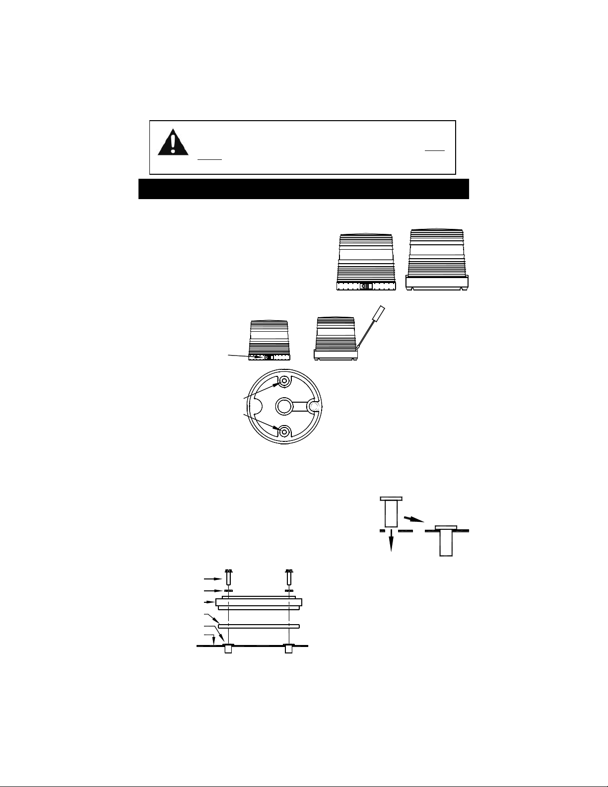
200ZL and 201ZL Permanent Mounting
1. Your new warning light comes complete with a
foam mounting gasket, two mounting screws,
two lock washers, and two well nuts.
2. These non-flanged lights come equipped with a
combination base, allowing the light to be
mounted on either a 1/2" NPT conduit pipe or
permanently mounted. For NPT pipe, mount the
light using the threaded entrance hole in the
base of the light, then skip to Step 11. For the
permanent mount, proceed to Step 3.
3. Carefully remove the dome as follows:
For models with a clamp
ring, use a Philip's head
screwdriver to remove the
screw in the clamp ring.
OR
For models without a clamp
ring, use a flathead
screwdriver to carefully pry
the dome off.
5. Remove the foam gasket from the
4. Examine the inside of
the base and use a
punch or drill to remove
the knock-outs present.
shipping box. Each gasket comes
furnished with three holes. (NOTE:
You might have to stretch the gasket to find the location of the holes.)
Place the gasket in the exact position the light is to be mounted
6. Using the gasket as a template, mark the holes on the mounting surface. Take care to
ensure that the gasket does not move while you are marking each of the holes.
7. Remove the gasket and drill a 3/8" hole in the outer two locations only.
CAUTION: Take care not to drill through the headliner of the vehicle below.
8. Push the enclosed rubber well nuts through the holes until the
bottom side of the wider lip rests on the surface of the vehicle.
9. If you are mounting the light on a vehicle and plan to wire it
through the roof of the vehicle remove the headliner from the
inside of the vehicle. Drill a 3/8" hole in the center marked
location. Place the light on the surface of the vehicle, routing
the wires through the hole.
Screw
Washer
Base of Light
Gasket
Well Nut
Mounting
Surface
10. To secure the light to your mounting
surface, align the holes with the well
nuts. Install the two screws through
the base, into the well nuts, and
tighten until snug.
11. Skip to the Wiring section.
-1-
Page 3

203MVL and 204MVL Permanent Mounting
Your new warning light comes
complete with the following:
Please note that these
models only use (2) of
the following: Mounting
screws, Lock washers,
(1) Light
(3) Mounting screws
(1) Foam mounting gasket
(1) Wire grommet
(2) Wire splicing terminals
1. Where applicable, carefully remove the headliner from the inside of the vehicle so that it
is not damaged during installation of the light.
2. Remove the foam gasket from the shipping box. Each gasket comes furnished with
mounting holes and a center wire hole. (NOTE: You might have to stretch the gasket to
find the location of the holes.) Place the gasket in the exact position the light is to be
mounted.
3. Using the gasket or base as a template, mark the mounting holes and the center hole for
the wires, if applicable, on the mounting surface. Take care to ensure that the gasket or
base does not move while you are marking each of the holes.
4. Drill a 3/16” hole in the marked spots
for the screws. If you are routing your
wires through the mounting surface,
drill a 5/16” hole in the center location
to route the wires through.
5. If applicable, insert the enclosed wire
grommet into the wire hole. If instead,
the wires will be running between the
base of the light and the mounting
Wire
Knockout
Bottom
View
surface, knock out the tab in the base
as pictured to the right.
and Hex nuts
Wire
Knockout
SP3860-1 LIGHTED SWITCH PANEL
(REAR VIEW)
(12 VDC ONLY !!!)
WARNING
LIGHT
ON
3
2
1
BLACK
RED
OFF
BLACK
GOOD
GOOD
CHASSIS
CHASSIS
GROUND
GROUND
FUSE
RED
5 AMP
TO +12 VDC
CONNECT
GOOD
GOOD
CHASSIS
CHASSIS
GROUND
GROUND
GREEN
Cut Short After
Pattern Selected
6. Place the light on the mounting surface, routing
the wires through the grommet if necessary.
Align the outer holes of the base with the holes
in the mounting surface, install the screws and
nuts, and tighten until snug.
Permanent Mount Wiring
1. The black wire is the ground lead and should be
connected to a good chassis ground.
2. Connect the red wire to the positive side of the
power through a switch and a 5 Amp fuse,
checking the label on the warning light for
proper voltage.
3. The Green wire is used for pattern selection.
Leave disconnected and see next page.
-2-
Page 4

Pattern Selection
Depending upon your model, pressing the pattern select button on the
cig plug, or touching the green wire to ground on hard-wired models, will
allow you to program the desired flash pattern.
The unit has 28 patterns to choose from. After the final pattern is
reached, the patterns will cycle through again. The UNIT will remember
the pattern it was in when turned off and display the same pattern when
re-activated.
Patterns
1. Slow Singleflash
2. Fast Singleflash
3. Superfast Singleflash
4. Beacon Fade
5. Pre Pops
6. Fast Doubleflash
7. Superfast Doubleflash
8. Fast Tripleflash
9. Fast Pre-Pop Tripleflash
10. Fast Quadflash
11. Fast Quadflash w/Post Pop
12. Quintflash
13. Pre-Pop Quintflash
14. Flicker
(DEFAULT)
For ease of navigation there are some patterns that you can skip to by holding the green
wire to ground (or pressing the Pattern Select button for mag mount models) for a multiple of
3 seconds, and then releasing it. For example, if at anytime you would like to go directly to
Pattern 1 (Slow Singleflash), simply touch the Pattern Select wire to ground for 3 seconds.
The LEDs should turn off when the green wire is connected to ground, then after 3 seconds,
the LED will flash once. Remove green wire form ground and the light will be in the Slow
Warn pattern.
Hold Pattern Select Button or
Touch Green Wire to Ground Light Flashes Pattern Becomes
3 seconds 1 Flash Pattern 1 - Slow Singleflash
6 seconds 2 Flashes Pattern 10 - Fast Quadflash
9 seconds 3 Flashes Pattern 21 - Fast Quadflash w/Post Pop,
Note: After programming the flash pattern, cut short and tape or cap off the Green wire
so that it does not come into contact with ground or power.
15. Delta Omega
16. Flicker-Flash
17. Super Combo/Mix Pattern
18. Slow Singleflash, Flicker
19. Fast Doubleflash, Fast Quadflash w/Post Pop Mix
20. Dual Quad w/Post Pop, Double, Quint, Quint, Flicker
21. Fast Quadflash w/Post Pop, Tripleflash, Flicker
22. Delta Omega, Flicker, Doubleflash
23. Medium Singleflash †
24. Medium Singleflash, Fast Singleflash †
25. Cycle all patterns
26. Steady On
27. Steady On (Low Power)
28. Medium Singleflash †
†
SAE Class 3 Approved Patterns when properly configured
Flash Pattern Shortcuts
Tripleflash, Flicker
If you have any questions concerning this or any other product,
please contact our Customer Service Department at (585) 226-9787.
If a product must be returned for any reason, please call the Customer Service
number listed above and ask for the Repair Department to obtain a Returned
Material Authorization number (RMA #) before you ship the product back. Please
write the RMA # clearly on the package near the mailing label.
-3-
 Loading...