

Page 1
INSTALLATION AND INSTRUCTION MANUAL
200AHL and 200AH8L Series 360° LED Lights
(4-LED Non-Rotating) (8-LED Rotating)
Please Note: These instructions are provided as a general guideline only. Specific mounting, wiring, and/
or weather-sealing may be necessary and are the sole responsibility of the installer. Star Headlight &
Lantern Co., Inc. assumes no responsibility for the integrity of the installation for this or any of its products.
featuring the
These lights are standard negative ground. Isolated or floating units for
positive ground vehicles are clearly labeled and are available upon request.
In this case connect the power to the proper polarity as marked on the wires.
CAUTION: All of our DC powered warning lights are polarity sensitive.
These lights are polarity protected only if the appropriate fuse is used.
All wires connected to the positive terminal of the battery should be
fused at the battery for their rated load. Testing the light before this
fuse is properly installed will void the warranty on the light.
PLIT447 REV. B 6/15/12
Page 2
Toggle Wing Mounted Models
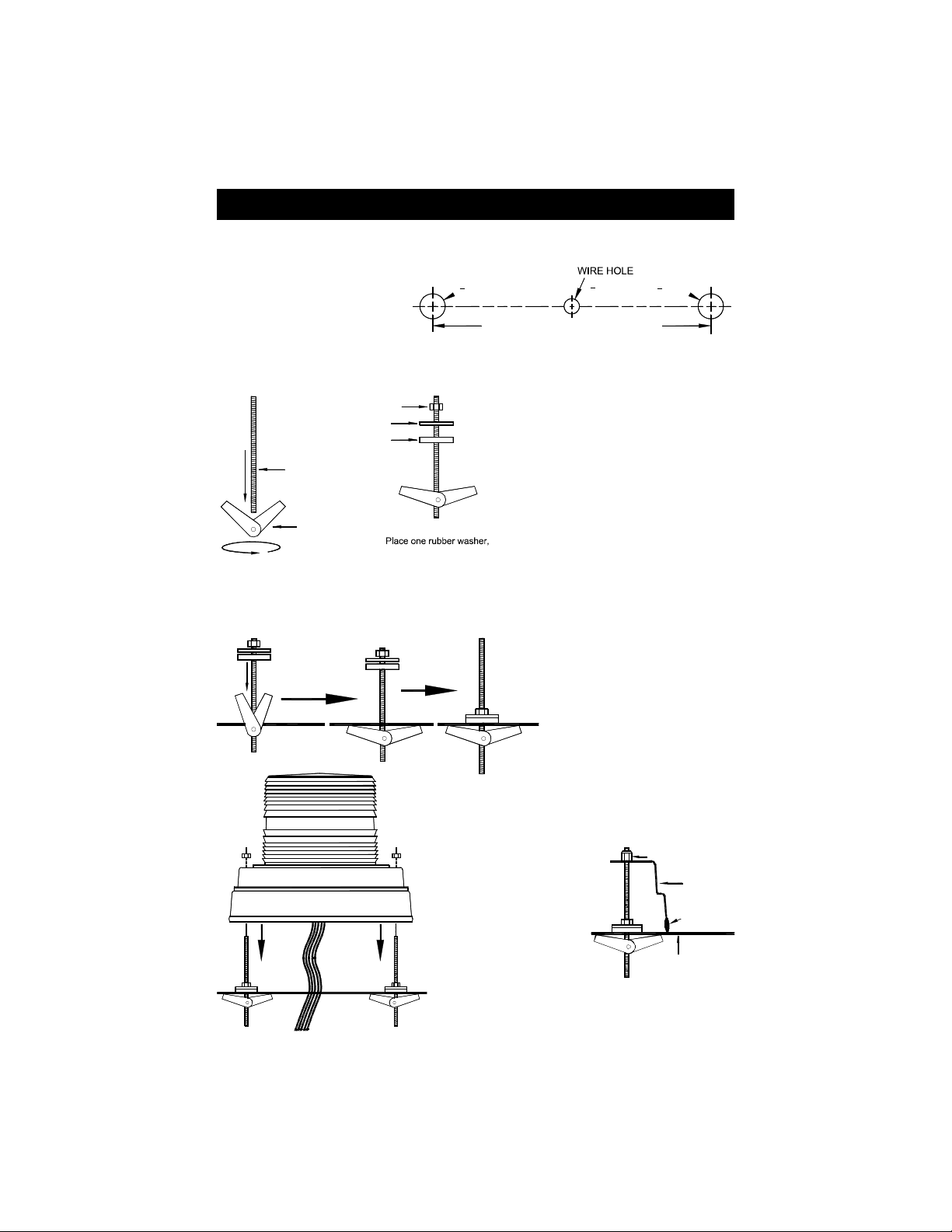
1. Your new warning light comes complete with a rubber mounting gasket, 2 toggle wings,
2 threaded rods, 2 neoprene washers, 2 steel washers, 2 nuts, and 2 self-locking nuts.
2. Mark two mounting holes on
7” centers and mark a spot
5
" DIA.
8
for the wire hole centered
directly between them.
7" CENTERS
3. Drill a 5/8" hole in the outer two marked locations. Then drill a 3/8" hole in the center
marked location for your wires to run through. CAUTION: Take care not to drill through
the headliner of the vehicle.
NUT
STEEL WASHER
RUBBER WASHER
THREADED ROD
4. Attach the rubber mounting gasket
around the base of the light.
5. Carefully remove the lens by
removing the three screws at the base
of the lens. Lift off the lens and
remove it taking care to ensure you do
not lose or destroy the lens gasket.
6. Attach a toggle wing to one end of one
of each of the threaded rods.
7. Place the rubber and steel washers
around each of the threaded rods
according to the diagram to the left.
Screw toggle wing
and threaded rod
together
TOGGLE WING
one steel washer, and
one nut on each rod
8. Then push the toggle wing through the top of one of the outer holes in the mounting
surface until it opens under the mounting surface.
3
" DIA.
8
5
" DIA.
8
Insert the threaded rod
and toggle wing
through the mounting
surface
MOUNTING SURFACE
Route wires through center hole, slide
light over rods, and secure with nuts
Tighten the nut,
securing the rod in
place
9. Tighten the nut down such
that it seats the steel washer
firmly against the rubber
washer, and the mounting
surface, holding the rod in
place. Repeat this for each
threaded rod.
10. Route the wires through the center hole, align
the outer holes in the base with the threaded
rods and slide the base onto the rods.
11. Fasten one of the
self-locking nuts to
each of the threaded
rods and tighten
until snug.
12. Once all of the nuts are tight and the base is
secure, reattach the outer lens(es).
-1-
SELF -LO CKI NG NUT
BASE
MOUNT ING
GAS KET
MOUN TING
SURF ACE
Page 3
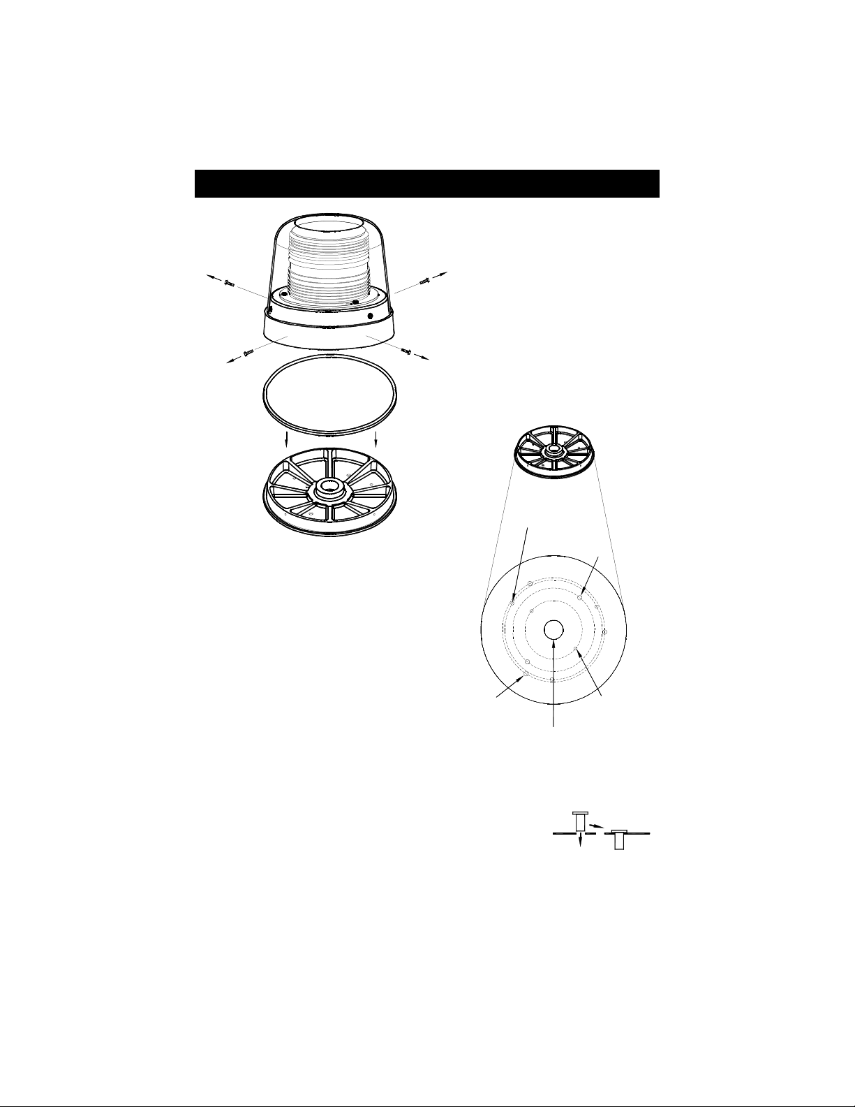
Plastic Base Mounted Models
Remove the 4 screws in the
side of the Aluminum housing
and slide the plastic base out
Gasket
Plastic Mounting Base
3 Locate the various knockouts on the bottom
of the base and determine which mounting
holes will work best for your application.
Clear the knockouts using a punch or other
appropriate tool.
4. Using the plastic mounting base as a
template, mark the appropriate holes on the
mounting surface. Take care to ensure that
the base does not move while you are
marking each of the holes.
1. Remove the four screws in the side
of the aluminum housing.
2. Slide the plastic base out of the
aluminum case. Take care not to
damage the gasket when separating
the plastic base from the aluminum
case.
0.196" Diameter
on 2.975" Radius
3 @ 120°
0.264" Diameter
on 2.5" Radius
2 @ 180°
101-AP
0.261" Diameter
on 3.125" Radius
3 @ 120°
1" NPT THREADED
PIPE MOUNT
0.189" Diameter
on 1.75" Radius
2 @ 180°
5. Remove the plastic mounting base and drill a 3/8" hole in the marked locations. Then, if
applicable, drill a 3/8" hole for the wires in the center of the outer holes.
CAUTION: Take care not to drill through the headliner of the vehicle below.
6. Push the enclosed rubber well nuts through the outer holes until the
bottom side of the wider lip rests on the surface of the vehicle.
7. Route the wires through the center hole, if applicable and align the holes with the well
nuts. Install the screws through the base, into the well nuts, and tighten until snug.
8. Once the plastic mounting base is installed on the vehicle, you may replace the light on
the base and reinstall the four screws that affix the light to the plastic mounting base.
-2-
Page 4

Wiring
CAUTION:
All of our DC powered warning lights are polarity sensitive. These lights are
polarity protected only if the appropriate fuse is used. All wires connected to the
positive terminal of the battery should be fused at the battery for their rated load.
Testing the light before this fuse is properly installed will void the warranty
Purple
on the light.
Black
: Ground lead - Connect to a good chassis ground.
Red
: Power - Connect to the positive side of your power source (+12-24VDC)
through a switch and a 5 Amp fuse. Check your light for proper voltage.
: Found only on the single color lights - Used for High/Low power selection.
• Leave disconnected for constant high power.
• Connect it to Ground for constant low power.
Orange
: Found only on dual color lights - Power for secondary color - Connect to the
• Connect it to Ground through a switch for High/Low select.
positive side of your power source (+12-24VDC) through a second switch and a
Green
White
5 Amp fuse. Check your light for proper voltage.\
: Pattern Select - Touch and release to ground to cycle through patterns.
: Synchronization - Cut short and cap off if not synchronizing this light with
additional lights. If synchronizing, set flash patterns BEFORE
connecting white wires together.
High/Low Power Settings
There are 3 modes these lights can be set to work in:
• Constant High Power
• Constant Low Power
• Manually Switched High/Low Power
(single color lights only)
By default all single color lights are set up for Manually Switched High/Low
power. This means that you can use the Purple wire to control whether the
light operates under high power (day mode) or low power (night mode):
• High Power Only: Cut the Purple wire short and tape it off.
• Low Power Only: Connect the Purple wire to Ground.
• Manually SwitchedHigh/Low Power:
Connect the Purple wire to Ground through a switch.
-3-
Page 5

Pattern Programming
1. Set the flash pattern using either the Green wire (recommended) or the internal jumper.
2. Power up the light by connecting the red and black wires.
3. You can program your light for any of the 12 different patterns in either of two “phases”.
(Refer to the pattern list on the following page).
4. The lights are preset at the factory for Pattern #6 (single-color non-rotating versions and all
dual-color versions) or Pattern #4 (single-color rotating versions). Cycle through the patterns by:
• Touching and releasing the green wire to ground.
• Removing the jumper from pins 2&3 and touching and releasing it to pins 1&2.
5. After the pattern has been set, tape or place a wirenut over the end of the green wire to
prevent it from coming into contact with ground again or replace the jumper on pins 2&3.
or
SHORTCUTS: There are a number of “shortcuts” available to make the programming of
Length of Hold
1 second Does Not
3 seconds
6 seconds
9 seconds
12 seconds 4 times
18 seconds 5 times
your light easier: Review the chart below for a list of how long you need to
touch the green wire to ground (or hold the jumper on pins 1 and 2) to go
to the desired pattern.
Unit Blinks
1 time
2 times
3 times
Single-Color Non-Rotating
And All Dual-Color
Models Jump To
Next Pattern
Pattern 1
Pattern 6
Pattern 13
Pattern 18
Steady Burn
Single-Color Rotating
Models Jump To
Next Pattern
Pattern 4
Pattern 6
Pattern 16
Pattern 18
Steady Burn
-4-
Page 6

Pattern List
Flash
Pattern
To set the light to one of the Pattern Defaults, hold green wire to GROUND for the
appropriate time as stated in pattern list.
Pattern
Type
#
1 K
2 L Fast Doubleflash 3.3
3 M Tripleflash † 2.5
4
5
6 F
7 G
8 H
9 I
10 J Variable AKA Delta-Omega 0.3
11 C Post pop 1.4CPS † 1.4
12 E Random 0.4CPS 0.4
13 K
14 L Fast Doubleflash 3.3
15 M Tripleflash † 2.5
16
17
18 F
19 G
20 H Singleflash †‡ 1
21 I
22 J Variable AKA Delta-Omega 0.3
23 C Post pop 1.4CPS † 1.4
24 E Random 0.4CPS 0.4
NA N/A Steady NA 18Sec
† - Approved patterns for SAE J845
‡ - California Title 13
Phase Pattern Description CPS
Flicker † 1
N
A5
O
A6
N
A5
O
A6
PSU Flicker (Non-Rotating Models)
CCW Rotation 1 (Rotating Models) †
PSU Random (Non-Rotating Models)
CCW Rotation 2 (Rotating Models)
1
Quadflash †‡
Quadflash w/Post-Pop †‡
Singleflash †‡
Doubleflash †‡
Flicker † 1
PSU Flicker (Non-Rotating Models)
CW Rotation 1 (Rotating Models) †
PSU Random (Non-Rotating Models)
CW Rotation 2 (Rotating Models)
Quadflash †‡
2
Quadflash w/Post-Pop †‡
Double flash †‡
Pattern
Defaults
(Non-R otatin g Only)
0.7
(Rotating Only)
1.3
0.6
2.7
1
1
1
1
(Non-R otatin g Only)
0.7
(Rotating Only)
1.3
0.6
2.7
1
1
1
3Sec
3Sec
6Sec
9Sec
9Sec
12Sec
To increment through pattern list, momentarily connect Green wire to GROUND and release.
-5-
Page 7

Synchronization of Multiple Lights
(Permanent Mount Versions Only)
You can synchronize up to six total approved lights.
If you will be synchronizing two or more units together, leave the white wires
disconnected until programming for each has been completed. Connect the
white wires from the units together ONLY AFTER PROGRAMMING them
all for the same
If you will be synchronizing your light with any of our products, please note the
following:
• All units that are to be synchronized MUST have the same
• To check pattern compatibility with other “S-Link” products, review the
product, noting the
compatible with others.
• Although the programmable
Types F, G, H, I, & J are fully compatible patterns with ALL of our other “S-Link” products.
1. Determine whether you want the two lights to flash alternately or simultaneously (Review the
diagram below for examples of Alternating and Simultaneous flashing).
2. Review the
product.
3. Select a
Pattern List
Pattern Type
4. Program each light according to the instructions enclosed with each. For lights that have
patterns with a Phase: All lights programmed for the same Phase will flash ON and OFF at
the same time (flash simultaneously). Lights that are programmed for different phases will flash
opposite one another (alternate).
5. After you have the correct patterns programmed for ALL of the lights you wish to
synchronize,
turn all of the lights off
6. Power all of the lights
up at the exact same
time to verify they are
flashing in the desired
pattern.
Power MUST
be applied to all
synchronized lights
simultaneously.
Excessive switch
bounce or
attempting to power
the units up
independently will
result in erratic
operation.
Pattern Type
Pattern Type
. Certain patterns are compatible with some lights, but not
Flash Patterns
for each synchronized product, noting the
that is compatible with all of the lights/flashers you will be synchronizing.
2 Complete flash cycles shown
Phase 1
Cycle 1
Phase 2
TIME
Phase 1
Cycle 2
(Phase MAY differ).
Pattern Type
can vary between our different lights, Pattern
Pattern Type
and connect the white wires from all units together.
Head 1
(ON) (OFF)
Head 2
2 Complete flash cycles shown
.
Pattern List
for each
Head 2Head 1
for each
Phase 2
-6-
Page 8

Low Voltage Detection
(Rotating Models Only)
These rotational beacons have low input voltage detection. With this feature the beacon senses
the input voltage and flashes a fast pattern (approximately 16 cycles per second) to indicate to the
user that the battery voltage is low (less than 10V). Once the input voltage returns to normal
(greater than 12V) the unit will return to the normal flashing.
Service
These lights use state-of-the-art Light Emitting Diode (LED) technology. These warning lights are
comprised of ultra-high intensity LEDs that are controlled by a solid state flasher unit to efficiently
produce light output with lifetimes up to 100,000 hours. Under normal circumstances, you will not
need to replace any LEDs in this light. If any of the LED's in your light do fail, please contact your
distributor for arrangements to have them repaired. The flasher unit and heads CANNOT be
serviced in the field and any attempt to do so will void the warranty.
The manufacturer warrants this LED l ight against factory defects in material and workmanship for five years
LED FIVE YEAR LIMITED WARRANTY
after the date of purchase. The owner will be responsible for returning to the Service Center any defective
item(s) with the transportation costs prepaid. The manufacturer will, without charge, repair or repl ace at its
option, products, or part(s), which its inspection determines to be defective. Repaired or replacement
item(s) will be returned to the purchaser with transportation costs prepaid from the service point. A copy of
the purchaser's receipt must be returned with the defective item(s) in order to qualify for the warranty
coverage. Exclusions from this warranty include, but are not limited to, domes, and/or the finish. This
warranty shall not apply to any light, which has been altered, such that in the manufacturer's judgment, the
performance or reliability has been affected, or if any damage has resulted from abnormal use or service.
There are no warranties expressed or implied (including any warranty of merchantability or fitness), which
extend this warranty period. The loss of use of the product, loss of time, inconvenience, commercial loss or
consequential damages, including costs of any labor, are not covered. The manufacturer reserves the right
to change the design of the product without assuming any obligation to modify any product previously
manufactured.
This warranty gives you specific l egal rights. You might also have additional rights that may vary from state to
state. Some states do not allow limitations on how long an implied warranty lasts. Some states do not all ow
the exclusion or l imitation of incidental or consequential damages. Therefore, the above limitation(s) or
exclusion(s) may not apply to you.
If you have any questions concerning this or any other product, please contact our
Customer Service Department to obtain a Returned Materials Authorization
Please write the RMA # clearly on the package near the mailing label.
Customer Service Department
at (585) 226-9787.
If a product must be returned for any reason, please contact our
number (RMA #) before you ship the product back.
-7-
 Loading...