

Star EV AP48-04, AP48-06, AP48-04-D, AP48-06-D Owner's Manual And Service Manual

Owner’s Manual and Service Guide
AP Series:
AP48-04, AP48-04-D, AP48-06, AP48-06-D

2
Thanks for buying the Star EV AP-Series. For better use, please read
through this manual before operating this vehicle to avoid any possible damage due to improper operation. Keep the manual handy aer
reading for future reference.
If you have any questions about the operation or maintenance of
your vehicle, please consult your Star EV dealer.
Important Information:
Important information is showed in following way in this manual:
WARNING: Failure to follow Warning instructions could result in severe injury or death to the vehicle occupants, bystanders or persons
inspecting or repairing the vehicle.
CAUTION: Failure to follow Caution instructions could cause damage
to the vehicle.
Note: Remove the seat and backrest wrapping film to prevent seat vinyl fading. If you have to stock the vehicle for long time, also remove
the seat and backrest wrapping film.

3
Vehicle Specifications
Operation
Important Labels
Functions
Operational Process
Charging Batteries
Safety
Maintenance
Battery
Cleaning
Recharging
Watering
Specific Gravity Test
Open-Circuit Voltage Test
Installation
Gear Box
Traction/Motor
Troubleshooting
Speed Controller
Brake System
Lubrication
General Maintenance Notes
Periodical Maintenance
Storage
Troubleshooting
Electric Wiring
Table of Contents
4
5
5
7
8
14
9
9
10
11
12
13
13
14
14
14
15
15
15
15
16
18
19
22

4
1: Vehicle Specifications
AP-Series 4-Passenger AP48-04, AP48-04-D
Passengers 4 Body Material Fiberglass
Battery System
Eight 6 V (48 V) batteries,
Trojan T-105
Front Suspension Independent, coil over shock
Motor Power 7 hp AC motor Rear Suspension Leaf spring and shock
Controller Power 450 A Curtis AC controller Steering System Rack and pinion
Top Speed
19.5 mph (20-25 mph if street
legal)
Brake System
Four-wheel hydraulic drum
brake
Load Capacity 780 lbs Tire Size 23x8.5-12 All-terrain tire
Dimensions 122” x 59” x 77” (L x W x H) Tire Pressure 14 psi
Weight w/ Batteries
1780 lbs no doors, 1885 lbs
with doors
Wheel Type 12” aluminum
Ground Clearance 5” Roof
Aluminum frame with fiberglass
Turning Radius 14.7 Windshield
AS1, DOT automotive windshield
Wheel Base 88” Drive Train Direct rear drive
Top Climbing Grade 20% Voltage Reducer
30 A, 48 V to 12 V reducer
included
Warranty Two year bumper-to-bumper warranty (less wear items)
AP-Series 6-Passenger AP48-06, AP48-06-D
Passengers 6 Body Material Fiberglass
Battery System
Eight 6 V (48 V) batteries,
Trojan T-105
Front Suspension Independent, coil over shock
Motor Power 7 hp AC motor Rear Suspension Leaf spring and shock
Controller Power 450 A Curtis AC controller Steering System Rack and pinion
Top Speed
19.5 mph (20-25 mph if street
legal)
Brake System
Four-wheel hydraulic drum
brake
Load Capacity 990 lbs Tire Size 23x8.5-12 All-terrain tire
Dimensions 153” x 59” x 77” (L x W x H) Tire Pressure 14 psi
Weight w/ Batteries
1905 lbs no doors, 2244 lbs
with doors
Wheel Type 12” aluminum
Ground Clearance 5” Roof
Aluminum frame with fiberglass
Turning Radius 19.8 Windshield
AS1, DOT automotive windshield
Wheel Base 118” Drive Train Direct rear drive
Top Climbing Grade 20% Voltage Reducer
30 A, 48 V to 12 V reducer
included
Warranty Two year bumper-to-bumper warranty (less wear items)
5
2: Operation
Important Labels
Please read the following labels carefully before operating the vehicle, and
promptly replace any labels which become unreadable or removed.
• Security Warning label under the dashboard
• Warning label under the dashboard
• Warning label beside the parking brake handle
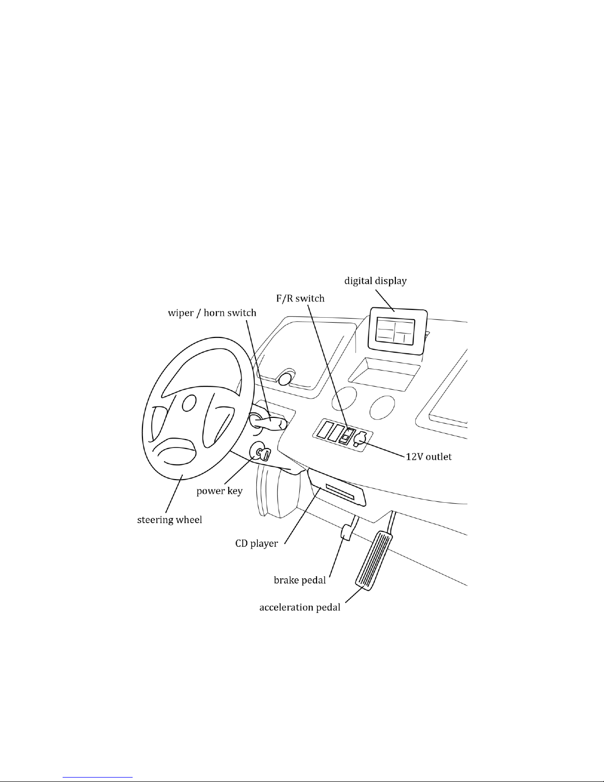
Functions

6
Power key: Controls the power supply of the whole vehicle. When the key is inserted into it and turned clockwise, it will switch on the lights, horn, and the control
system; when the key is turned back, the power will be switched o.
Acceleration pedal: Controls the speed. It should be depressed slowly. The vehicle
speeds up with the gradual stepping-down, and reaches the full speed when the
pedal is stepped to the bottom. The vehicle slows down when the pedal is released
gradually. When the pedal is fully released, electric brake works.
Brake pedal: Decelerates the vehicle.
F/R switch: This switch is a three-position button. Depressing the upper part (F)
makes the vehicle move forwards while depressing the lower part (R) makes the
vehicle move backwards, and the middle is neutral. NOTE: The buzzer will sound
when the lower part of this button is depressed to give warning to the people
around your electric vehicle.
7
Hand-brake lever: Parks and brakes the vehicle.
Steering wheel: Controls the driving direction.
Headlight switch: Controls the headlight.
Direction light switch: Controls the turning signal.
Wiper and horn switch: Controls the wiper and horn.
Emergency stop switch: Stops the power of the whole vehicle in case of emergen-
cy. NOTE: Before you switch on the vehicle, always check the status of this switch
to make sure that it is in the OFF position.
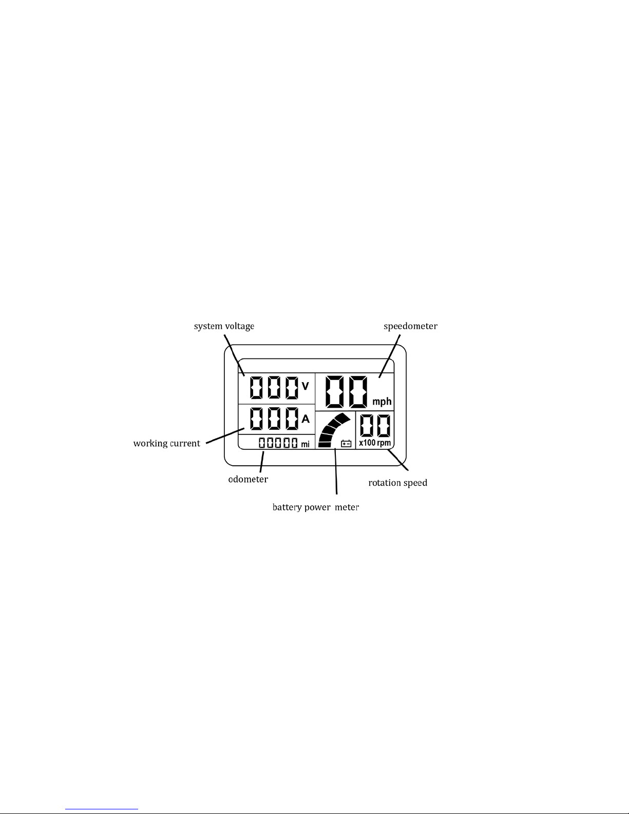
Digital display: This meter shows information including lights, speed, range, hand
brake, and battery power.
Operational Process
Starting the vehicle
1. Select F for Forward or R for Reverse from F/R button.
2. Switch on power with key.
3. Release the handbrake lever.
4. Depress the acceleration pedal smoothly.
WARNING: If you switch on power key first before selecting Forward or Reverse on
F/R Button, the vehicle will not run.
Stopping the vehicle
1. Step brake pedal to decelerate the vehicle until it stops completely and
shi F/R button to neutral position.

8
2. Engage the handbrake lever to park the vehicle.
3. Release the service brake.
4. Switch o all lights.
5. Switch o the power key and take out the key.
Charging Batteries
• CAUTION: There are two dierent kinds of chargers for this vehicle. One
is an exterior charger and the other is a built-in (on-body) charger. Before
you use the charger, read the charger operation manual.
• Explosive hydrogen gas is produced while battery is charged. Only charge
the battery in well-ventilated areas.
• Before using the charger, check if the battery charger you are using is
correctly rated for your local AC electricity network.
• Do not disconnect the DC output cord from the battery receptacle when the
charger is ON, otherwise an arc could occur which may cause an explosion.
• Do not open the housing of the charger. Only a qualified electrician should
open the housing of the charger.
• The charger should be stored in safe and dry room with good ventilation.
The charger should be packed properly if not used for long time.
Charging Procedure
Turn o the power of the vehicle before charging.
For a exterior charger with one set of batteries:
1. Connect charger to DC receptacle on the vehicle.
2. Connect the charger to AC power.
3. Turn on the charger.
4. Turn o the charger when the batteries are fully charged. Disconnect the
charger from AC power first, and then disconnect the charger with AC
receptacle.
For on-board (built-in) charger:
1. Connect the charger with AC power.
2. Turn on the charger.
3. Turn o the charger when the batteries are fully charged, disconnect the
charger with AC power.
 Loading...