

Starcom Systems Triton User Manual

TRITON
User Guide
Version 2.0

Triton User Guide
February 2013
COPYRIGHT © STARCOM SYSTEMS, ALL RIGHTS RESERVED.
Distribution of substantively modified versions of this document is prohibited
without the explicit permission of the copyright holder.
Distribution of this work, or of a derivative thereof, in any standard (paper)
book form for commercial purposes is prohibited unless prior permission is
obtained from the copyright holder.
DOCUMENTATION IS PROVIDED «AS IS» AND ALL EXPRESS OR IMPLIED
CONDITIONS, REPRESENTATIONS AND WARRANTIES, INCLUDING ANY
IMPLIED WARRANTY OF MERCHANTABILITY, FITNESS FOR A PARTICULAR
PURPOSE OR NON-INFRINGEMENT, ARE DISCLAIMED, EXCEPT TO THE
EXTENT THAT SUCH DISCLAIMERS ARE HELD TO BE LEGALLY INVALID.
2

Triton User Guide
Contents
1 Introduction _________________________________________ 5
2 Package Contents _____________________________________ 6
3 Product Description ____________________________________ 7
Sensors __________________________________________ 8
Audible signals ____________________________________ 9
Technical specifications ______________________________ 9
Industry approvals and certifications __________________ 11
4 Configuration ________________________________________ 12
Downloading the Software __________________________ 12
Installing the Software _____________________________ 12
Installing the Update _______________________________ 16
Installing the cable driver ___________________________ 18
Inserting the SIM card _____________________________ 19
Attaching the battery ______________________________ 21
Connecting the unit to the computer ___________________ 22
Configuring the unit _______________________________ 23
Network settings __________________________________ 29
Transmission Rates settings _________________________ 31
Hardware settings _________________________________ 33
Saving the configuration ____________________________ 34
Configuring a new unit with the saved configuration ______ 34
5 Testing _____________________________________________ 35
TCP test _________________________________________ 35
GPS test _________________________________________ 36
Unit Status _______________________________________ 37
6 Installation _________________________________________ 38
7 Monitoring __________________________________________ 39
Home ___________________________________________ 40
3

Triton User Guide
Resources _______________________________________ 41
Units _______________________________________ 41
Groups _____________________________________ 44
Users ______________________________________ 45
Perimeters __________________________________ 48
Plans ___________________________________________ 52
Monitor _________________________________________ 58
Map ____________________________________________ 61
Reports _________________________________________ 70
Scheduled reports ____________________________ 72
Profile __________________________________________ 75
Help ____________________________________________ 77
Appendix A – Unit Communication in Starcom Systems _________ 78
Appendix B – Contacts __________________________________ 80
4
Triton User Guide
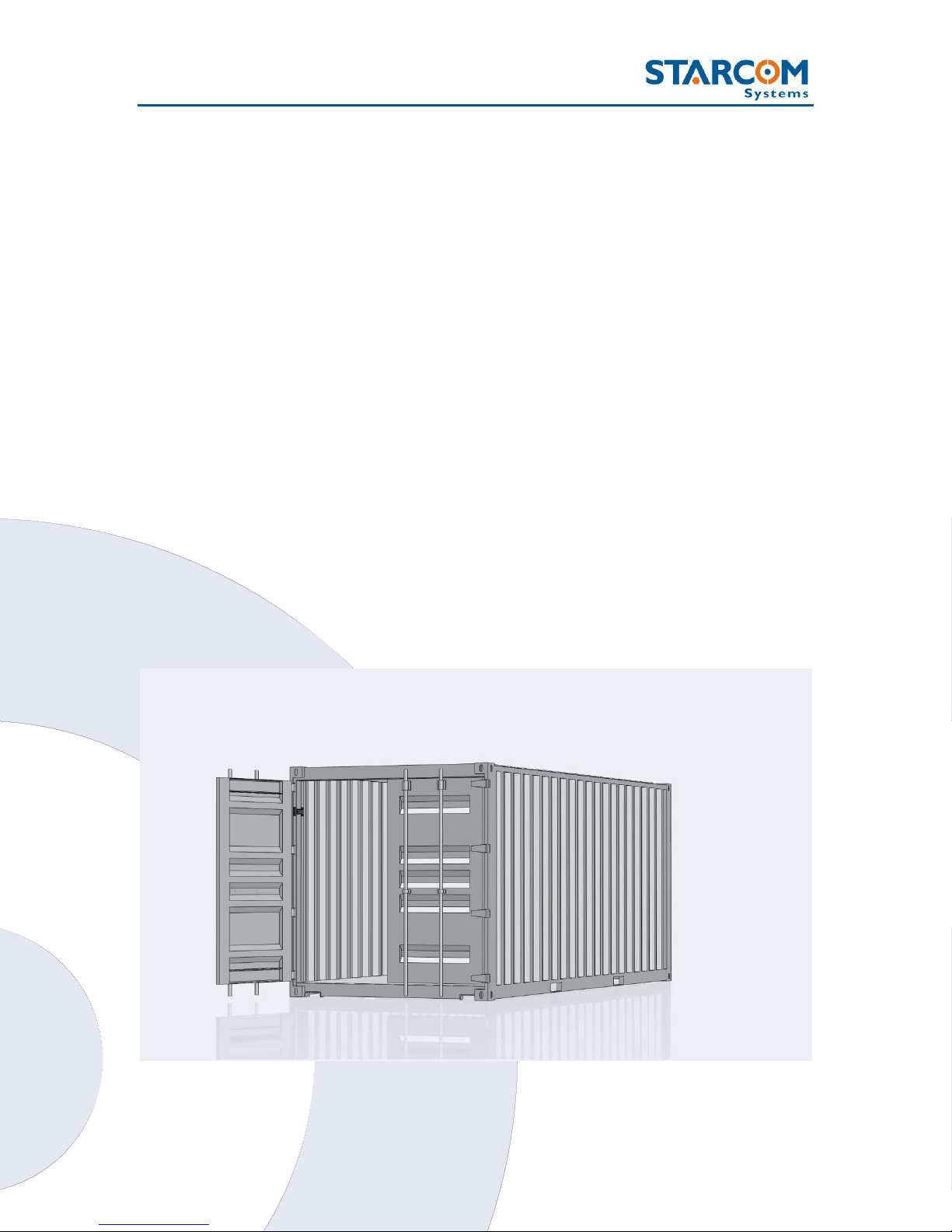
1 Introduction
Triton is a sophisticated real-time container tracking device designed for
security and management purposes. It allows full control of various events
and situations by automatic remote monitoring, provides system stability and
continuity of operations.
Utilizing its built in sensors and GPS / GPRS facilities for communication the
system can detect when the container has reached the customer and inform
the recipient of every movement of the container. Any damage, blow or
breaking into the container can be reported by email and SMS.
The device is easily installed on the container door frame and performs the
monitoring of the container state and location. The system provides alerts on
various events, such as door opening, breaking in through the side wall, door
forcing, container tilt, fall, impact, etc.
5
Triton User Guide
2
3
4
1
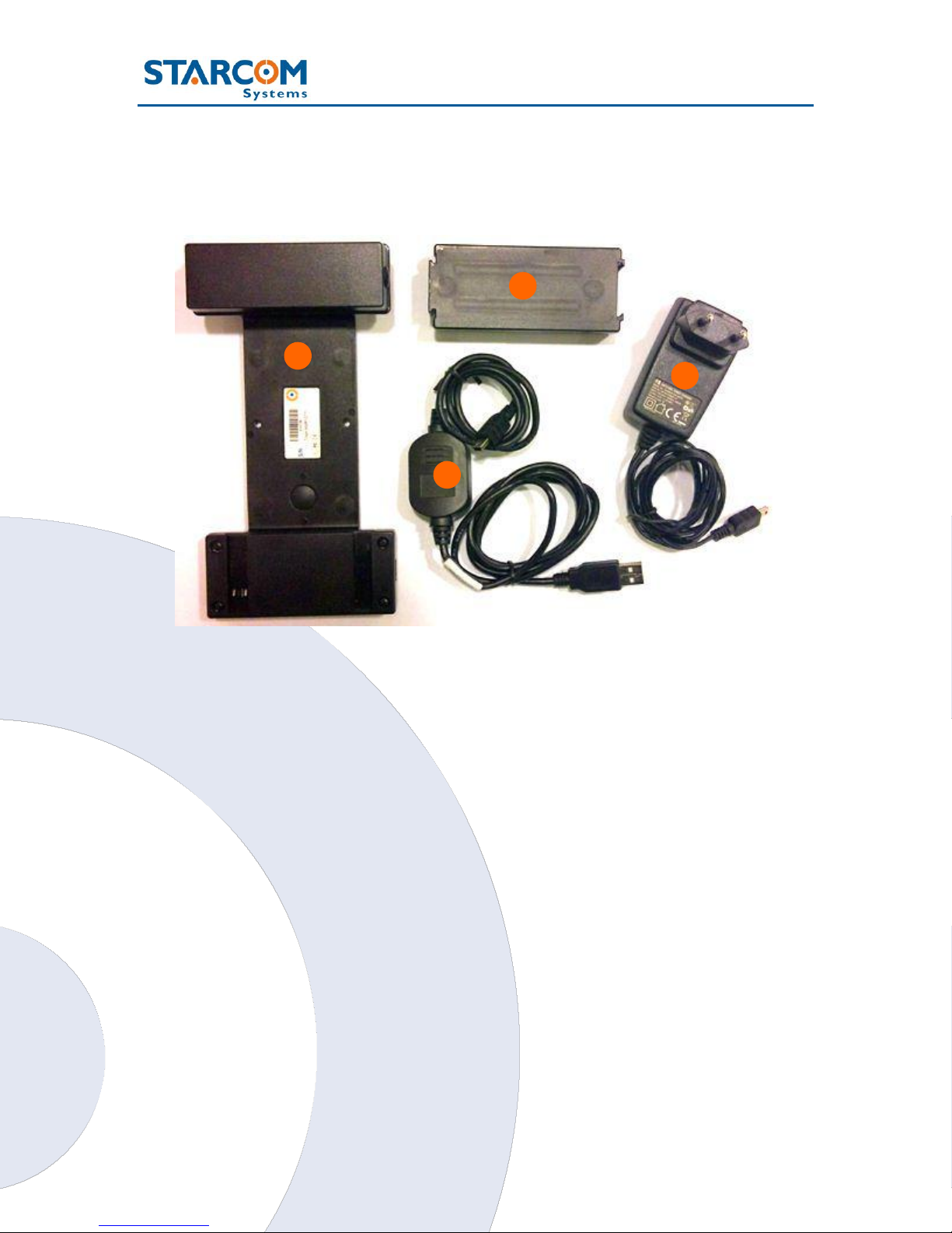
2 Package Contents
1. Triton unit
2. Battery
3. AC charger
4. Triton RS232 cable with USB connectors
WARNING: Use only the charger provided by Starcom Systems to charge the
Triton battery. Using any other charger could damage your device or battery.
6

Triton User Guide
1
2
3
4
5
6
7
8
9
9
9
9
3 Product Description
1. Central Arm – central part of Triton with the Install and Door buttons
which connects the two side compartments. This part contains the
magnets for fast attachment to the container door frame and two holes,
in case an attachment with screws is required (optional). When Triton is
installed in the container, this part is located inside the container.
7

Triton User Guide
2. Battery, CPU, GSM and GPS Compartment (System Core) – wide
side compartment which contains the CPU, GSM and GPS modules, the
SIM card slot and the light sensor. The battery is connected to this
compartment. When Triton is installed in the container, this part is located
inside the container.
3. Antennas Compartment – thin side compartment, which contains the
GSM and GPS antennas. The Operation button is located in this
compartment. When Triton is installed in the container, this part is located
outside the container.
4. Light sensor – sensor which detects light change inside the container
(e.g. breaking into the container).
5. Door button – button which responds when the container door is
open/closed.
6. Operation button – button which serves for testing the Triton operation
after installation.
7. Mini USB output – used for connecting the unit to the computer with
RS232 cable.
8. Install button – button which is triggered when the unit is
installed/uninstalled (attached/removed from the container door frame).
9. Magnets – 4 industrial strength magnets used for fast attachment of the
unit to the container door frame.
Sensors
Triton incorporates several sensors to monitor and report various event
types.
Light sensor – detects a change of light inside the container (e.g.
breaking into the container).
Acceleration sensor – detects impacts to the container.
Temperature sensor – detects temperature around the unit (can be
configured for high and low temperature alerts from -127°C to +127°C).
8

Triton User Guide
Supply
Voltage
3.7 V
Temperature
Operational
Storage
-20°C to 60°C
-40°C to 85°C
Operating Humidity
Up to 90%
Measurements
195 x 96 x 40 mm
Cellular Modem
GSM
Quad Band (850, 900, 1800,
1900)
Built in antenna
Network
Data
GPRS and SMS
Messages
SMS
GPRS
Encrypted Protocol
TCP/IP over PPP
Audible signals
The unit uses audible signals (beeps) to announce its activity. When you
insert the battery in the device, it will sound one (1) audible signal (beep), to
indicate that it was activated.
After this, the device will connect to the cellular network. Once the device
performs a successful connection to the cellular network, it will sound two (2)
audible signals (beeps).
At the same time, the device will connect to the GPS and get the location.
Once the device performs a successful connection to GPS, it will sound three
(3) audible signals (beeps).
Technical specifications
9

Triton User Guide
GPS
Receiver and Antenna
Protocol
Positioning accuracy
Navigation Update Rate
Navigation method
Time to First Fix (TTFF)
Internal
NMEA (Binary format)
Position: 10 m CEP (50%)
Velocity: 0.2 m/s (50%)
1 second (default)
All-In-View solution
2-Satelite solution
Hot Start: 2 sec
Warm Start: 10 sec
Cold Start: 50 sec
CPU Capacity
Static RAM
Nonvolatile Memory
Flash Memory
128 kb
34 kb
2048 kb
Inputs
Pushbutton
Light Sensor
3
1
Battery Pack
Type
Capacity
Li-Ion
5200 mAh
Power
Consumption
Sleep/Idle
GPS only
GPRS only
GPS and GPRS
0.05 mAh
75 mAh
100 mAh
165 mAh
Com Port
RS232
115,200 bps (default)
10

Triton User Guide
Industry approvals and certifications
For available certificates, see:
http://wiki.starcomsystems.com/wiki/index.php/Marketing#Certifications.
11
Triton User Guide
4 Configuration
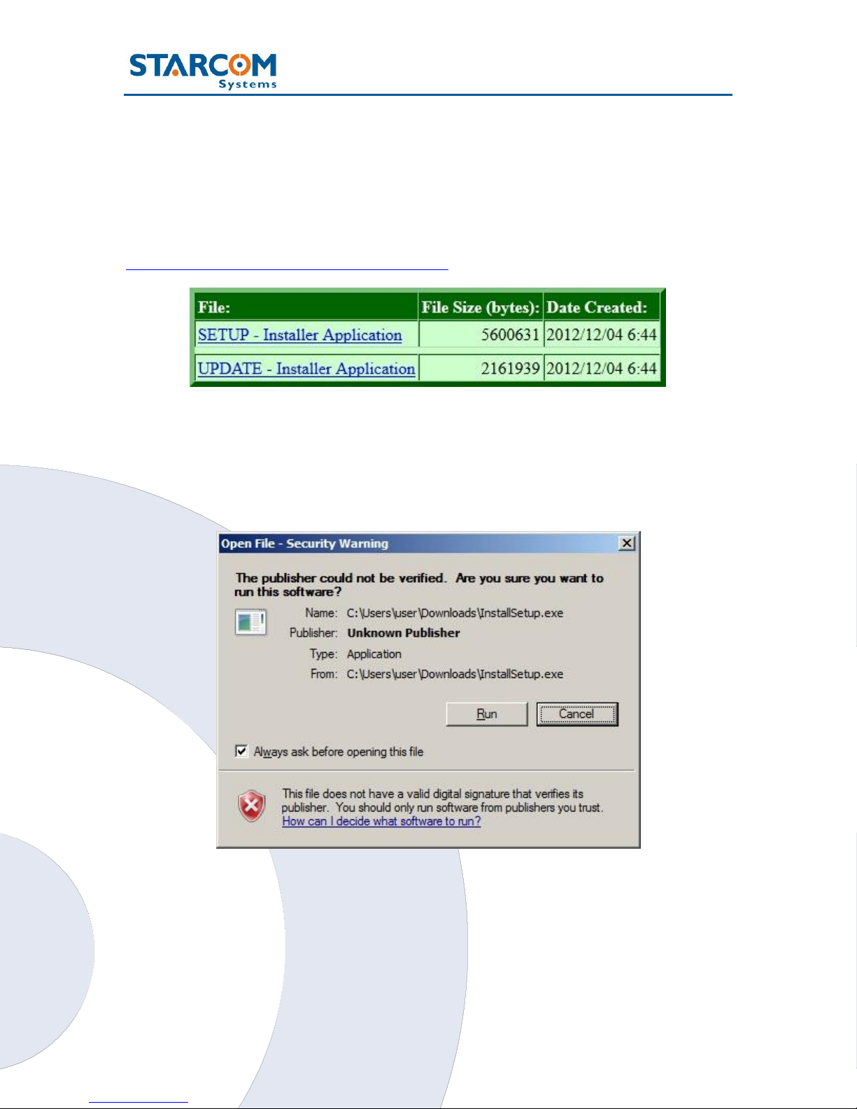
Downloading the Software
Download the Installer application setup file and update available at:
http://www.starcomsystems.com/0601ca
Installing the Software
Locate the folder where you saved the installer setup file. Double-click the
InstallSetup.exe. The Open File dialog box appears.
Click Run. A Windows Security dialog box appears. Click Yes. The Welcome
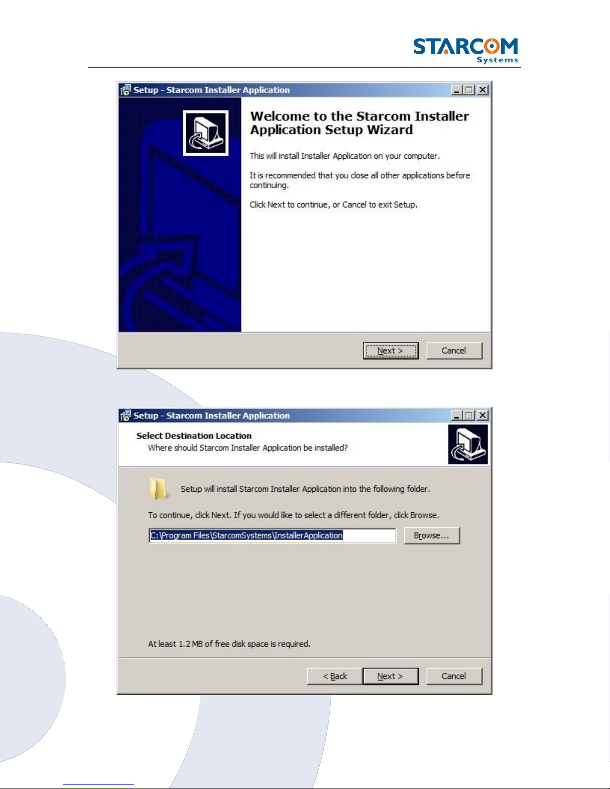
to the Starcom Installer Application Setup Wizard window appears.
12
Triton User Guide
Click Next. The Select Destination Location window appears.
13
Triton User Guide
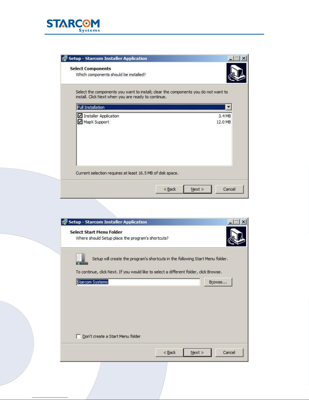
Click Next. The Select Components window appears.
Click Next. The Select Start Menu Folder window appears.
14
Triton User Guide
NOTE: Select Don’t create a Start Menu folder checkbox, if you do not
want to create a start menu folder.
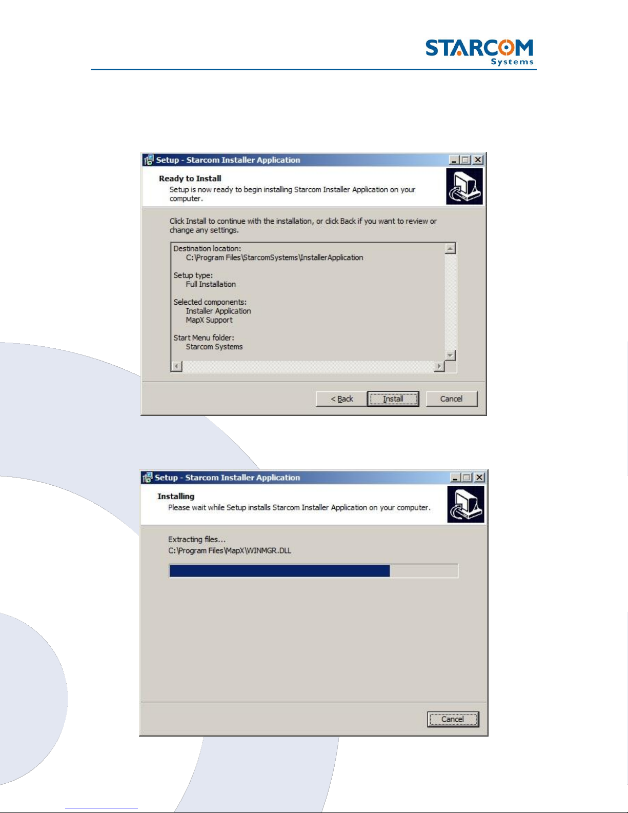
Click Next. The Ready to Install window appears.
Click Install. The installation starts and a progress bar appears in the
window, indicating the progress of the installation.
15
Triton User Guide
When the installation is complete, the Completing the Starcom Installer
Application Setup Wizard window appears.
Click Finish.
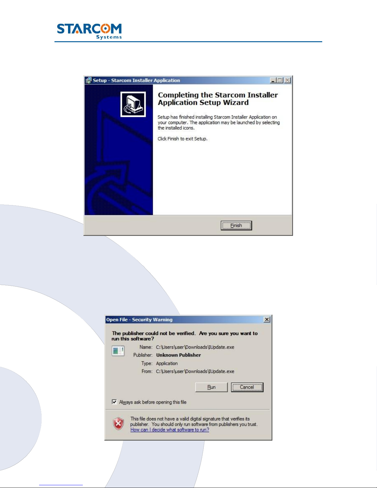
Installing the Update
To install the Installer update software, locate the folder where you saved
the update file. Double-click IUpdate.exe. The Open File dialog box appears.
16
Triton User Guide
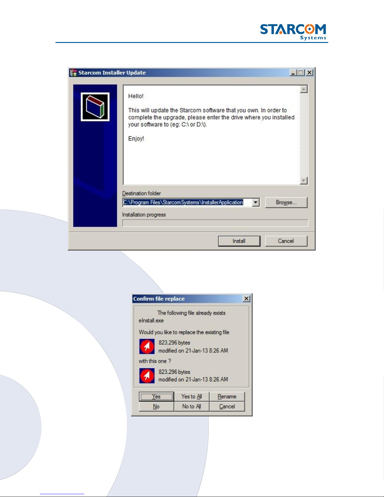
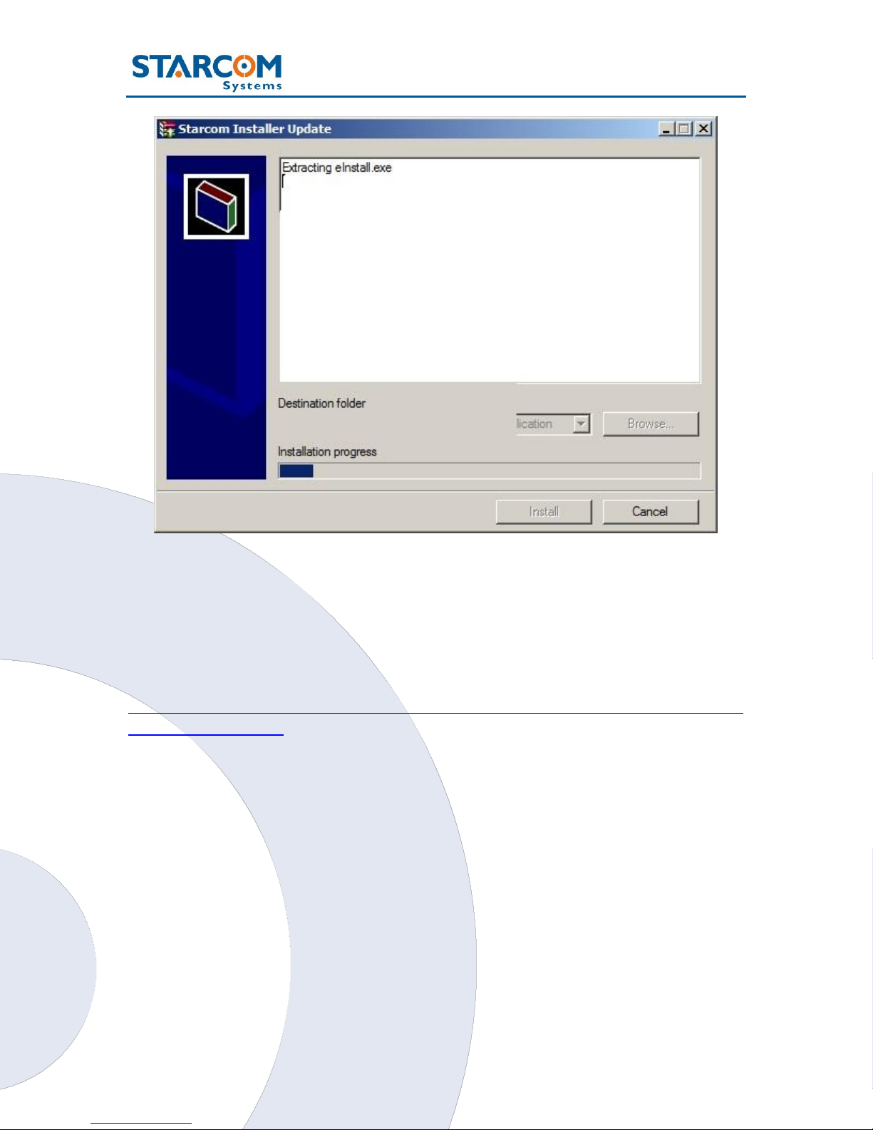
Click Run. The Starcom Installer Update window appears.
Verify that the Destination folder points to the location where the Starcom
Installer software is installed and click Install. A Windows Security dialog
box appears. Click Yes. The Confirm file replace dialog box appears.
Click Yes to All. The installation starts and a progress bar appears in the
window, indicating the progress of the installation.
17
Triton User Guide
The Starcom Installer Update window closes, when the update is complete.
Installing the cable driver
The Triton cable driver can be downloaded from the following link:
http://wiki.starcomsystems.com/wiki/index.php/Triton#Driver_for_USB_to_S
erial_adapter_cable.
The zip file contains a User Manual which explains the driver installation
process. Follow the instructions in the Manual to install the cable driver.
18
Triton User Guide
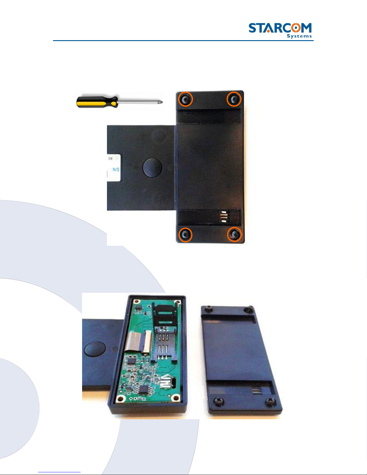
Inserting the SIM card
Remove the back panel of the wide compartment by unscrewing the back
panel screws (4 screws total), as shown in the following image.
Gently push and pull back the plastic SIM card holder to release and open the
SIM card slot. Raise it to an upright position.
19
Triton User Guide
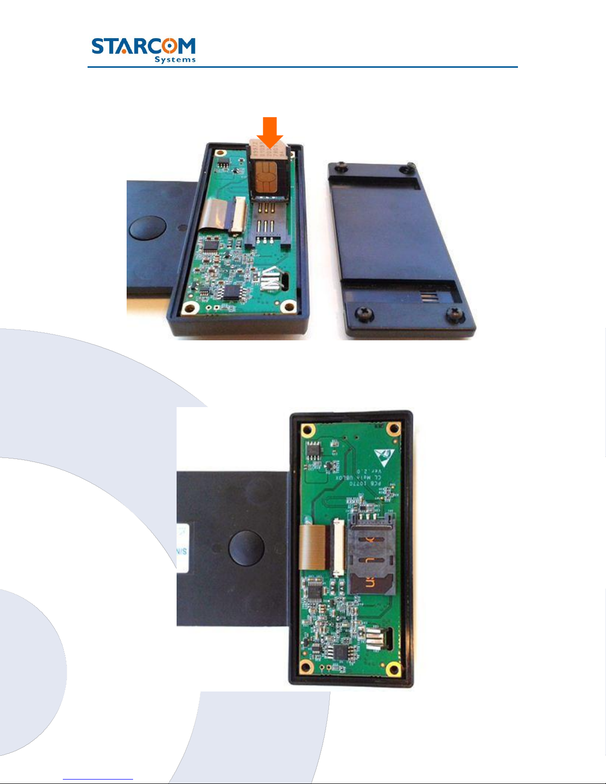
Insert the SIM card in the SIM card slot with its gold contacts facing down
and its cut-off corner facing out the SIM card slot, as shown in the following
image.
Lower the SIM card holder back to the horizontal position. Gently press and
push the SIM card holder forward to snap it back into place. Close the cover
and fasten the screws.
20
Triton User Guide
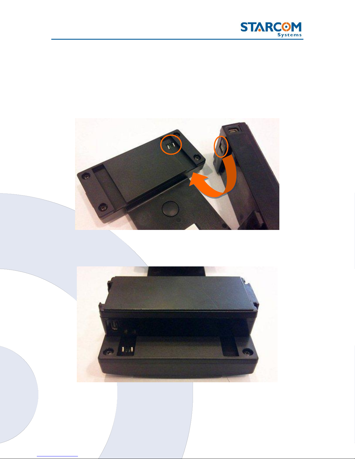
Attaching the battery
NOTE: Before installation, please verify that the battery is fully charged.
Charge the battery for at least 12 hours prior to first use. After that, charge
the battery for at least 3 hours before each use.
Hold the battery so that the contacts on the Triton wide side compartment
are facing the contacts on the battery.
Gently slide the battery into the wide side compartment.
21
Triton User Guide
AC
output
Triton
output
Push the battery all the way, until it lines up with the compartment.
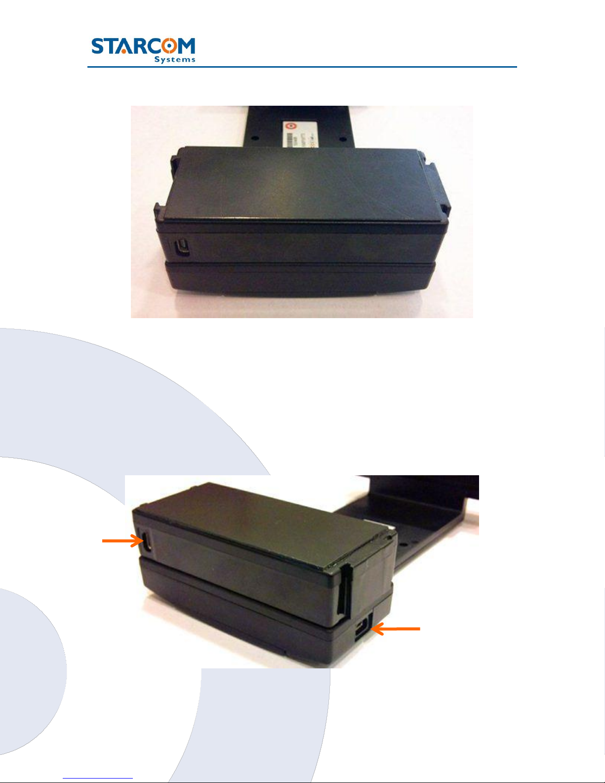
Connecting the unit to the computer
Connect the Triton USB cable to the USB output on the unit and to the USB
port on your computer.
NOTE: Make sure that you connect the cable to the Mini USB output on the
unit and NOT to the output on the battery, which is intended for the AC
charger.
charger
cable
22
Triton User Guide
NOTE: Triton unit enters sleep mode to save the battery power whenever
possible. This means that during the testing process you must keep the unit
awake in order to check its functionality.
After you insert the SIM card and the battery, the unit will spend about 5
minutes to attempt connection to the cellular network and to GPS. During
this time it will be awake, which will allow you to connect it to the computer
and start the configuration.
After the unit performs the connection attempt, it will enter sleep mode. You
can wake the unit by pressing on the Install and Door buttons several times.
To keep the unit awake during the testing process, you can do one of the
following:
Put the unit into testing mode using the Terminal and \tf1 command (see
below);
Change the unit transmission rate to 30 seconds;
Keep the Install button pressed.
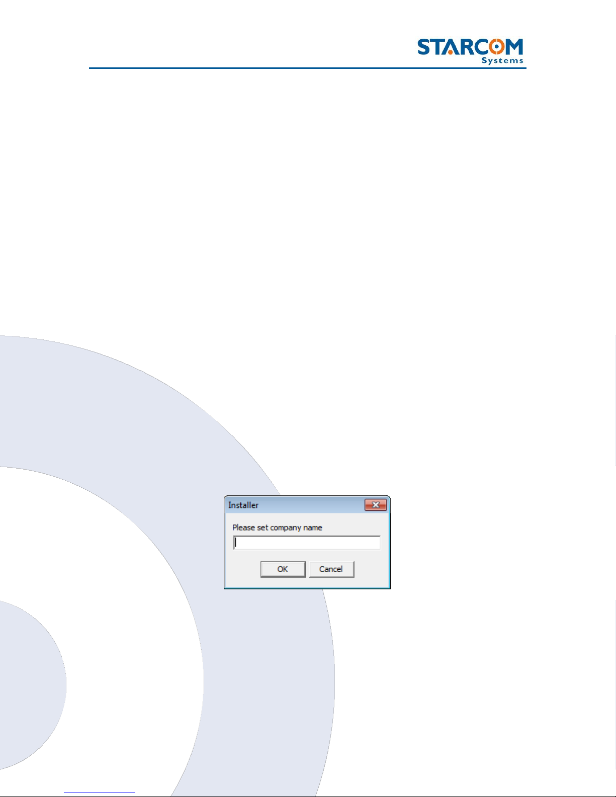
Configuring the unit
To open the Installer application, from the Start menu select Starcom
Systems > Installer Application. The Installer company name window
appears.
Enter your company name and click OK. The Installer window appears.
23
Triton User Guide
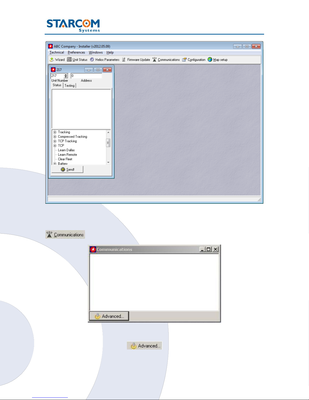
Click Technical > Communications, or press the Communications button
on the taskbar at the top of the window.
Click the Advanced button . The Communications Window will
appear.
24
 Loading...