

Starcom Systems Helios User's Manual Manual

Helios User’s Manual Guide
Starcom GPS Global Solutions
Helios User’s Manual Guide
Version 2.0

Helios Users Guide
October 2015
COPYRIGHT © STARCOM GPS GLOBAL SOLUTIONS, ALL RIGHTS
RESERVED.
Distribution of substantively modified versions of this document is prohibited
without the explicit permission of the copyright holder.
Distribution of this work, or of a derivative thereof, in any standard (paper)
book form for commercial purposes is prohibited unless prior permission is
obtained from the copyright holder.
DOCUMENTATION IS PROVIDED «AS IS» AND ALL EXPRESS OR IMPLIED
CONDITIONS, REPRESENTATIONS AND WARRANTIES, INCLUDING ANY
IMPLIED WARRANTY OF MERCHANTABILITY, FITNESS FOR A PARTICULAR
PURPOSE OR NON-INFRINGEMENT, ARE DISCLAIMED, EXCEPT TO THE
EXTENT THAT SUCH DISCLAIMERS ARE HELD TO BE LEGALLY INVALID.
www.starcomgpsglobal.com 2

Helios Users Guide
Contents
1 Introduction 6
2 Package Contents 7
Helios evaluation kit 8
Simulator description 9
3 Product Description 12
Unit board main components 13
Helios models 14
Technical specifications 16
Industry approvals and certifications 17
4 Configuration 18
Downloading the Software 18
Installing the Software 19
Installing the Update 24
Inserting the SIM card 26
Attaching the battery (optional) 29
Connecting the unit to the computer 33
Configuring the unit 35
General settings 40
Network settings 41
Transmission Rates settings 43
Inputs settings 45
Outputs settings 47
Logic settings 49
Hardware settings 51
Analog input configuration on Helios TT and Basic 53
Fuel algorithm v2 54
Jamming detection 57
Driver IDs settings 58
Saving the configuration 59
Configuring a new unit with the saved configuration 59
Configuring multiple units using the wizard 59
Helios Hybrid configuration 62
www.starcomgpsglobal.com 3

Helios Users Guide
5 Testing 63
TCP test 63
GPS test 65
Unit Status 66
6 Installation 67
Wiring considerations and safety guidelines 67
Tools required for installation 69
Positioning the unit in the vehicle 70
Donning the Helios TT waterproof casing 71
Helios TT pin out 76
Helios Basic 10-pin pin out 80
Helios Advanced 24-pin pin out 83
Helios Hybrid connection 87
7 Monitoring 88
Home 89
Resources 90
Units 91
Groups 94
Drivers 96
Users 97
Perimeters 100
Plans 103
Monitor 110
Map 112
Reports 119
Scheduled reports 122
Profile 124
Help 126
Wiring 126
www.starcomgpsglobal.com 4
Helios Users Guide
Appendix A – Unit Communication in Starcom Systems 128
Appendix B – Configuring Mileage 130
Appendix C – Central Locking System Configuration 133
Appendix D – Immobilizer and Gradual Stop 137
Appendix E – Connecting a Siren 138
Appendix F – Fuel Management 139
Appendix G – CAN Bus Connection 145
Appendix H – Using Keypad with RF Relay 152
Appendix I – Cellular Phone Commands 155
Appendix J – Contacts 156
www.starcomgpsglobal.com 5
Helios Users Guide
1 Introduction
Helios is a real-time vehicle tracking device designed for fleet management and
security applications.
It offers over 200 unique features, such as fuel consumption monitoring, extra
digital inputs for connection of various external sensors, offline communication
option, built-in accelerometer, OTA (over-the-air) programming, etc.
The system allows configuring a wide variety of events for fleet manager and
the communication channels which define where and how the notifications are
transmitted.
www.starcomgpsglobal.com 6
Helios Users Guide
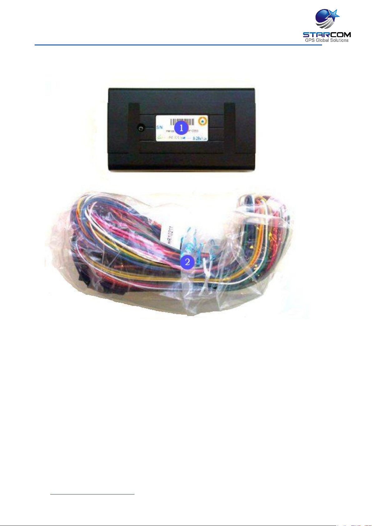
2 Package Contents
1. Helios unit
2. Helios wire harness
www.starcomgpsglobal.com 7
Helios Users Guide
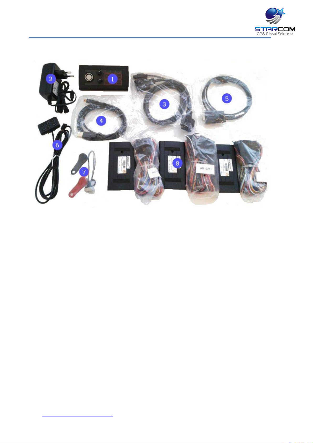
Helios Evaluation Kit
Evaluation kit package includes:
1. Simulator
2. Simulator power supply
3. Simulator to Helios connection cable
4. Simulator USB to Mini USB cable
5. RS232 cable
6. Keypad
7. Dallas keys
8. 3 Helios units with wire harnesses
www.starcomgpsglobal.com 8

Helios Users Guide
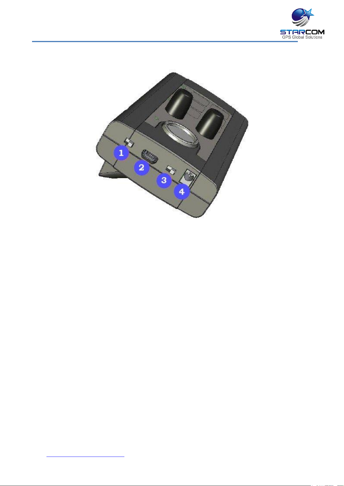
Simulator description
The Simulator was developed for Helios testing and presentation purposes. It
simulates the vehicle behaviour and alarm triggers, the LEDs light up to
indicate the unit input/output response. It can serve as an efficient tool in
training your employees and evaluating their performance. The Simulator is an
effective, professional sales tool which can be used to demonstrate the system
advantages and present them to your customers.
Front panel
1. Power LED
2. Dallas Key socket
3. Analog input knobs
4. Output simulator LEDs
5. Input simulator buttons and LEDs
www.starcomgpsglobal.com 9
Helios Users Guide
Left panel
1. DLS/KYPD – Dallas Key / Keypad switch
2. Mini USB connector
3. ON/OFF – Power switch
4. Power connector
www.starcomgpsglobal.com 10
Helios Users Guide
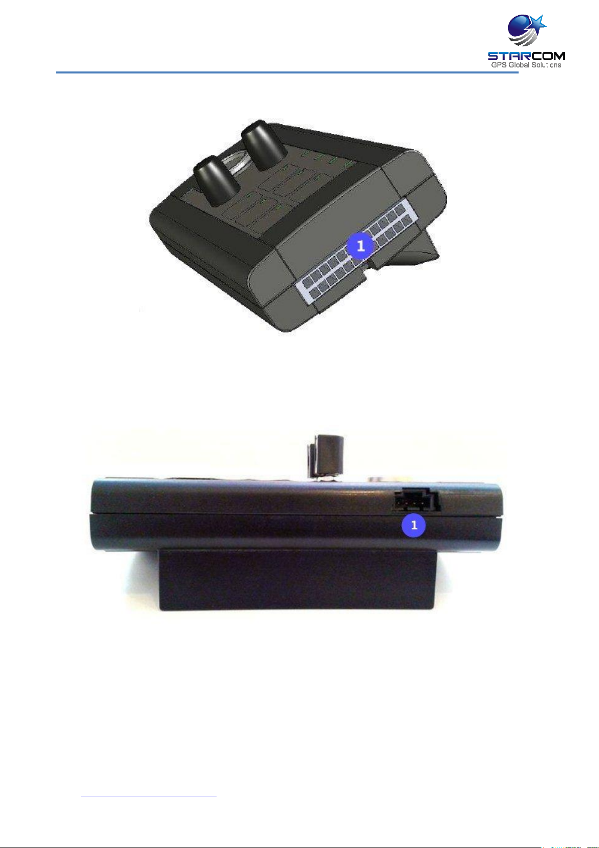
Right panel
1. 24-pin connector
Back panel
1. Keypad connector
NOTE: When connecting a keypad, make sure to place the DLS/KYPD switch
on the left panel in the KYPD position.
www.starcomgpsglobal.com 11
Helios Users Guide
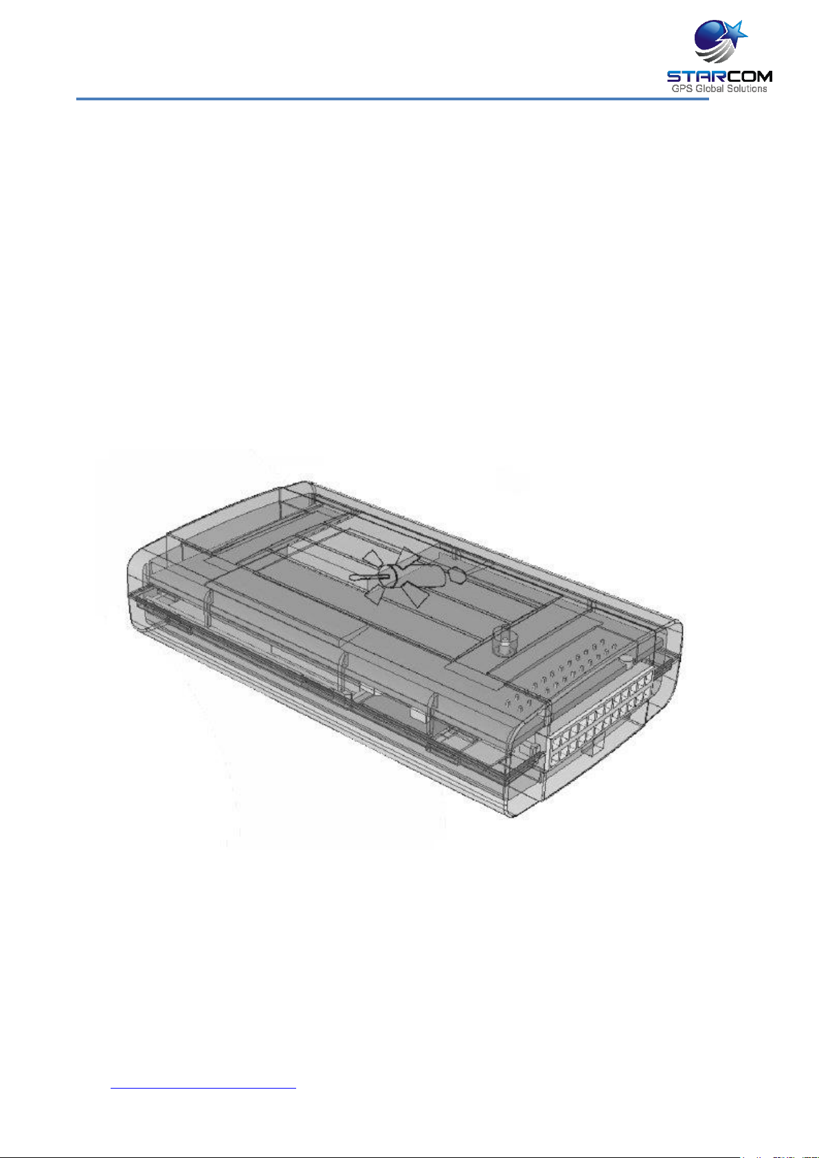
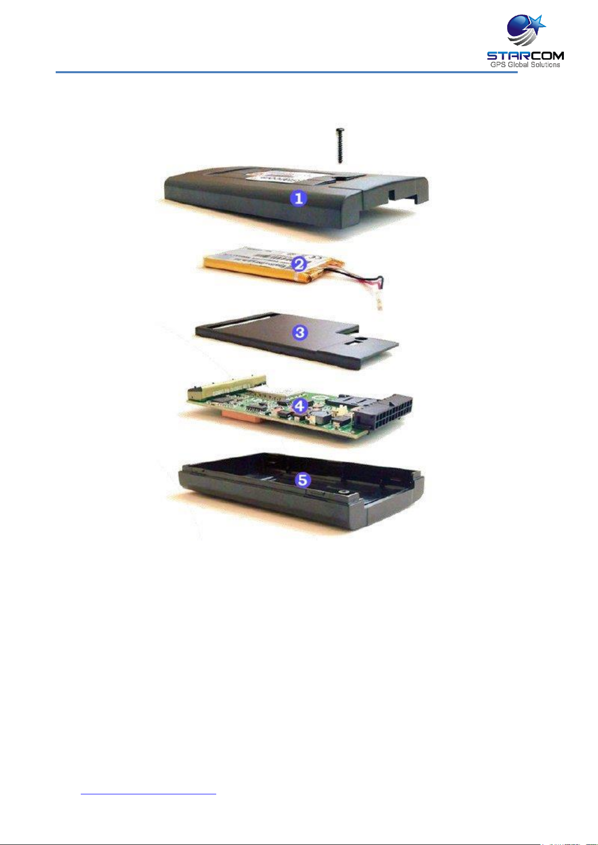
3 Product Descriptions
1. Bottom cover – plastic cover which snaps onto the top cover and is secured
with a screw.
2. Battery – backup battery (optional).
3. Divider – plastic divider which snaps onto the top cover. The backup battery
is placed on top of this divider.
4. Unit board – printed circuit board with electronic components which is
secured to the top cover.
5. Top cover – plastic cover which covers the GPS antenna. This side should be
facing upwards when the unit is installed in the vehicle.
www.starcomgpsglobal.com 12
Helios Users Guide
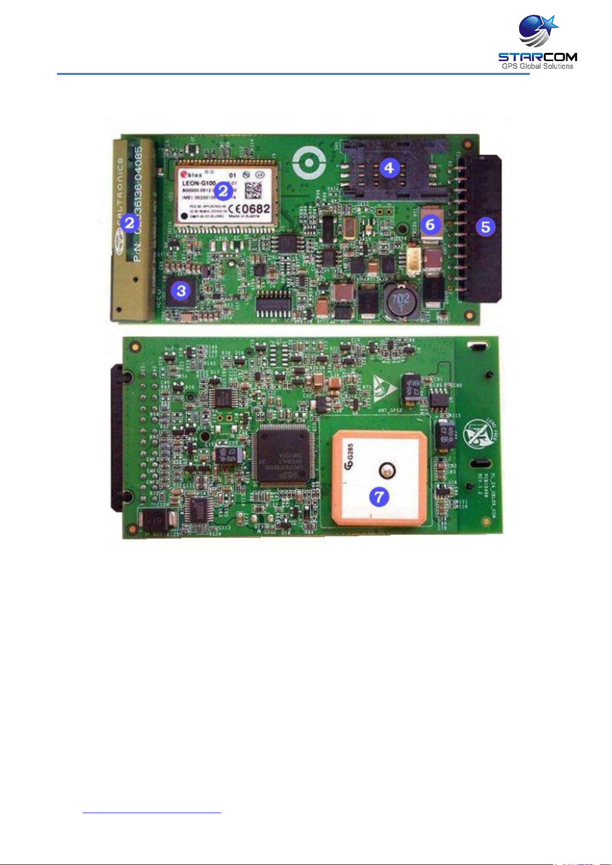
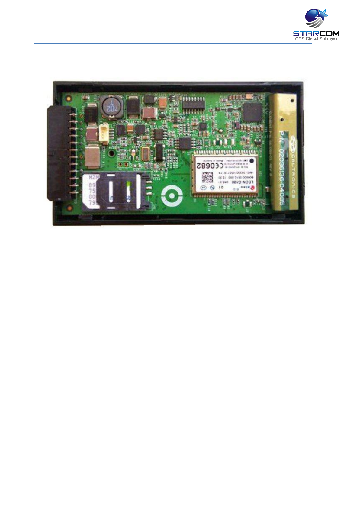
Unit board main components
1. GSM modem
2. GSM antenna
3. GPS chipset
4. SIM card holder
5. 24-pin / 10-pin connector
6. Fuse
7. GPS antenna
www.starcomgpsglobal.com 13
Helios Users Guide
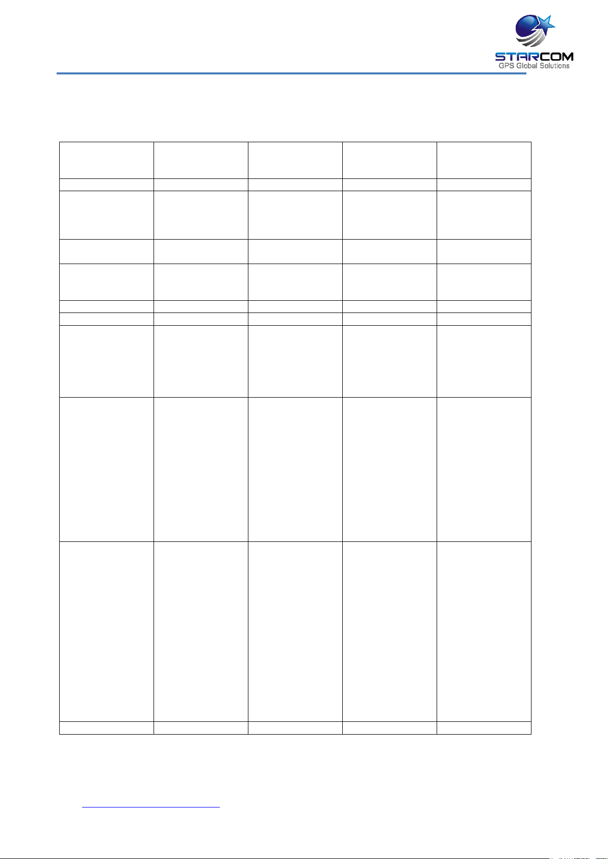
Helios
TT
Helios
Advanced
Helios
Advanced
U Blox
Helios
Hybrid module
GPS + + + +
GSM + +
(optional 3G,
HSDPA and
CDMA)
+
(optional 3G,
HSDPA and
CDMA)
+
(optional 3G,
HSDPA and
CDMA)
Satellite
Connectivity
- - -
+
Connector
10 pin Molex
24 pins Molex
24 pins Molex
For Helios
Advanced +
10 pins Molex
Accelerometer
+ + +
+
CAN Bus - + + +
Usage
Track and trace
Full fleet and
security
features
Can be used as
standalone
alarm system
Full fleet and
security
features
Can be used as
standalone
alarm system
Full fleet and
security
features
Can be used as
standalone
alarm system
Advantages
Low cost
Waterproof IP65
(optional)
Allows a tow
detection with
very low power
consumption
Additional
inputs/outputs
Built-in
accident and
harsh braking
detection
Additional
inputs/outputs
Built-in
accident and
harsh braking
detection.
External
Antenna
fixtures
Constant
communication
around the
world, even
without cellular
coverage
Additional
inputs/outputs
Built-in
accident and
harsh braking
detection
I/O
2 digital inputs
(one digital
input can be
used as an
analog input)
1 digital output
1 COM port
8 digital inputs
3 analog inputs
4 digital outputs
1 pulse counter
RS232
Can Bus
*Hands Free
input
iButton /
Keypad / RF
Keypad /
Remote Control
input
8 digital inputs
3 analog inputs
4 digital outputs
1 pulse counter
RS232
Can Bus
*Hands Free
input
iButton /
Keypad / RF
Keypad /
Remote Control
input
8 digital inputs
3 analog inputs
4 digital outputs
1 pulse counter
RS232
dedicated to
Hybrid module
Can Bus
*Hands Free
input
iButton /
Keypad / RF
Keypad /
Remote Control
input
SIM card
Micro-SIM
Mini-SIM
Mini-SIM
Mini-SIM
Helios Models
There are four Helios models:
www.starcomgpsglobal.com 14

Helios Users Guide
* When Hands Free Kit is used, the unit is left with 5 digital inputs and 2
analog inputs only.
For connector pin out information, see Helios TT pin and Helios Advanced+ 24-
pin pin out (Chapter 6 – Installation).
www.starcomgpsglobal.com 15
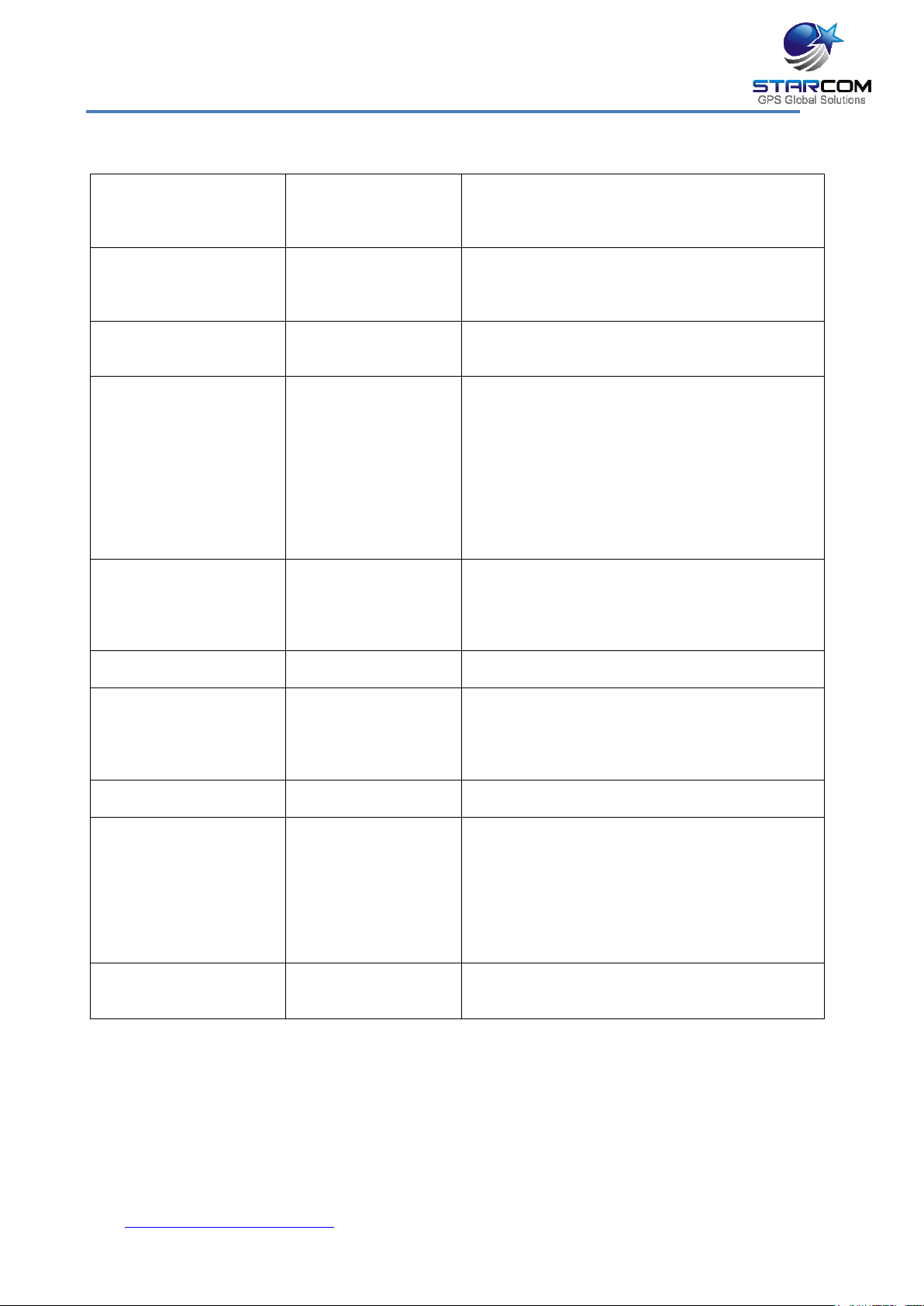
Helios Users Guide
CPU
Type
Memory
NXP ARM Cortex-M3
Static RAM: 128kb
ROM: 34kb
Flash: 2048kb
Power
Voltage Range
Consumption
8 V – 28 V (supported in same unit)
3 mA in low power mode
up to 120 mA in working mode
can reach up to 300 mA if battery is charged
Backup Battery
(optional)
Type
Power
Lithium-ion Polymer
3.75 V, Helios Advanced+: 950 mAh / Helios
TT: 550 mAh
GPRS – Cellular
Modem
Satellite Modem
(external device)
Data Messages
GSM
Antenna Type
Network Channels
Connection
SMS
GPRS
Quad Band (850, 900, 1800, 1900).
Built in (concealed)
GSM, CDMA, HSDPA, SMS
3G (optional)
RS232
Encrypted Protocol
TCP/IP
Location
Type
Time to First Fix
(TTFF)
Positioning Accuracy
Antenna Type
GPS / GLONASS (optional)
2 sec (hot start)
10 m CEP (50%)
Velocity: 0.2 m/s (50%)
Built in (concealed)
COM Port
Type
Speed
RS232
115,200 bps (default)
I/Os
(check per model)
Digital Inputs
Digital Outputs
Analog Inputs
Pulses Counter
CAN Bus
Helios Advanced+: Max 8 / Helios TT: Max 2
Helios Advanced+: Max 4 / Helios TT: Max 1
Helios Advanced+: Max 3 / Helios TT: Max 1
Max 1 (Helios Advanced+ only)
Included (Helios Advanced+ / Basic)
Accelerometer
(check per model)
Type
Purpose
3-Axis, 20 mg accuracy, up to 8 g
Identify and report events of impact, accident
Alarm System
Size
Weight
Helios Advanced+:
21H x 60W x 107L (mm)
Helios TT:
21H x 60W x 57L (mm)
Helios Advanced+:
150 (grams) 5.29 (Oz)
Helios TT:
120 (grams) 4.23 (Oz)
Environmental
Operating Temp
Storage Temp
Humidity
-40°C (-40°F) to 60°C (140°F)
-40°C (-40°F) to 85°C (185°F)
Max 50%
Technical specifications
www.starcomgpsglobal.com 16
Helios Users Guide
Industry approvals and certifications
https://trello.com/b/YrNJfXNd/certificates
www.starcomgpsglobal.com 17
Helios Users Guide
4 Configuration
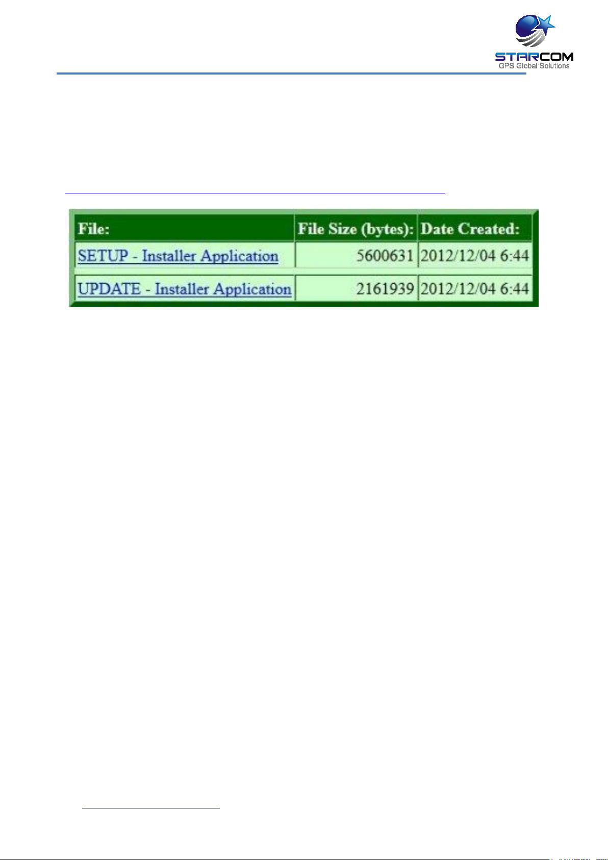
Downloading the Software
Download the Installer application setup file and update available at:
https://trello.com/c/k8Z8QHzZ/1-installer-application-download
www.starcomgpsglobal.com 18
Helios Users Guide
Installing the Software
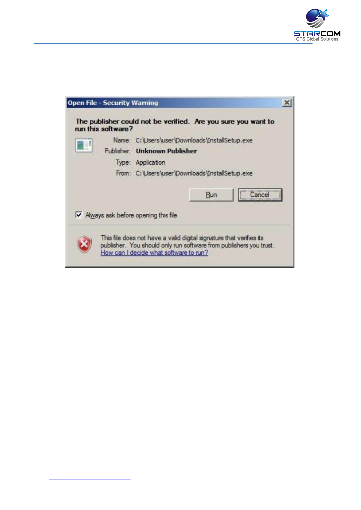
Locate the folder where you saved the installer setup file. Double-click the
InstallSetup.exe. The Open File dialog box appears.
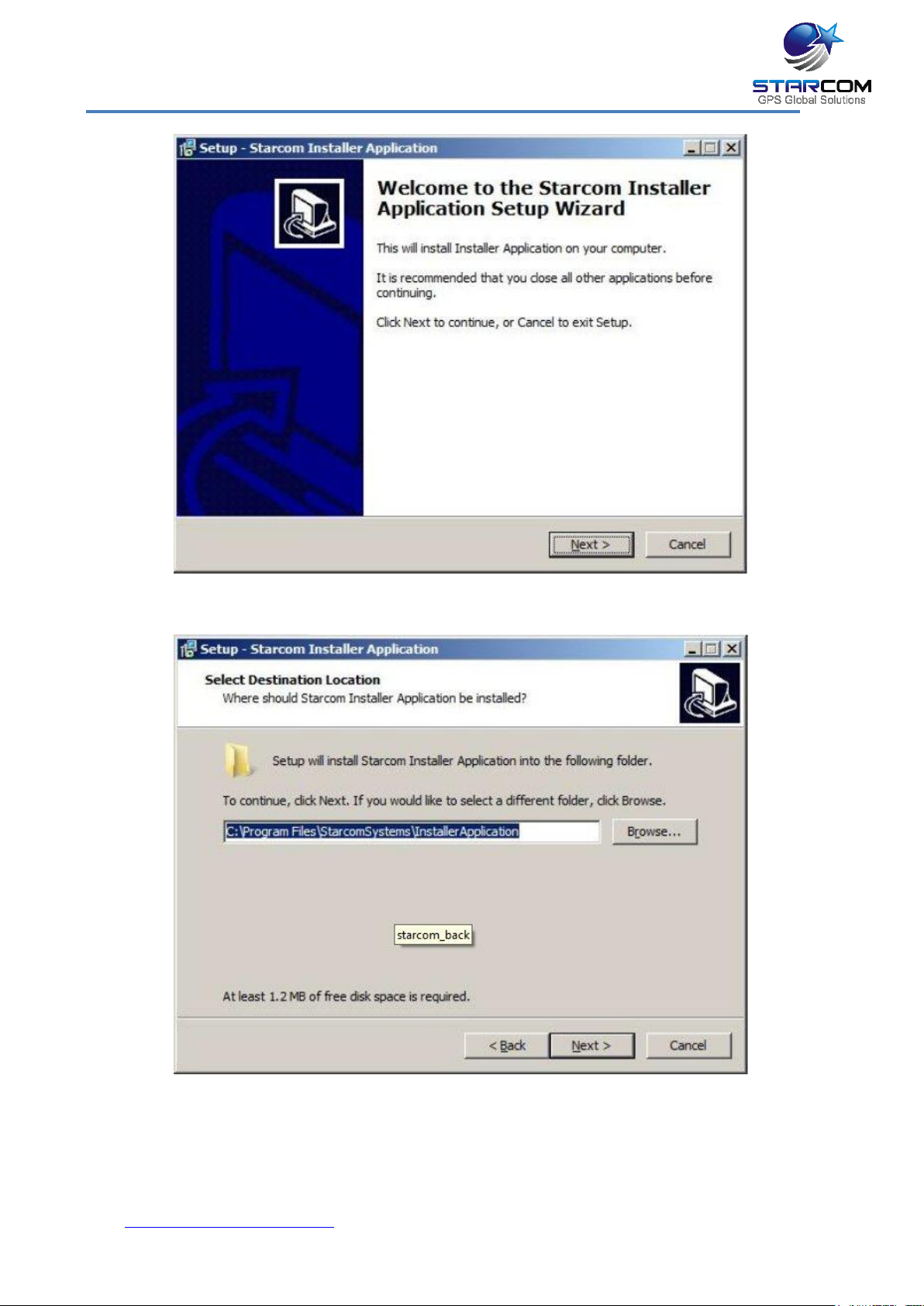
Click Run. A Windows Security dialog box appears. Click Yes. The Welcome to
the Starcom Installer Application Setup Wizard window appears.
www.starcomgpsglobal.com 19
Helios Users Guide
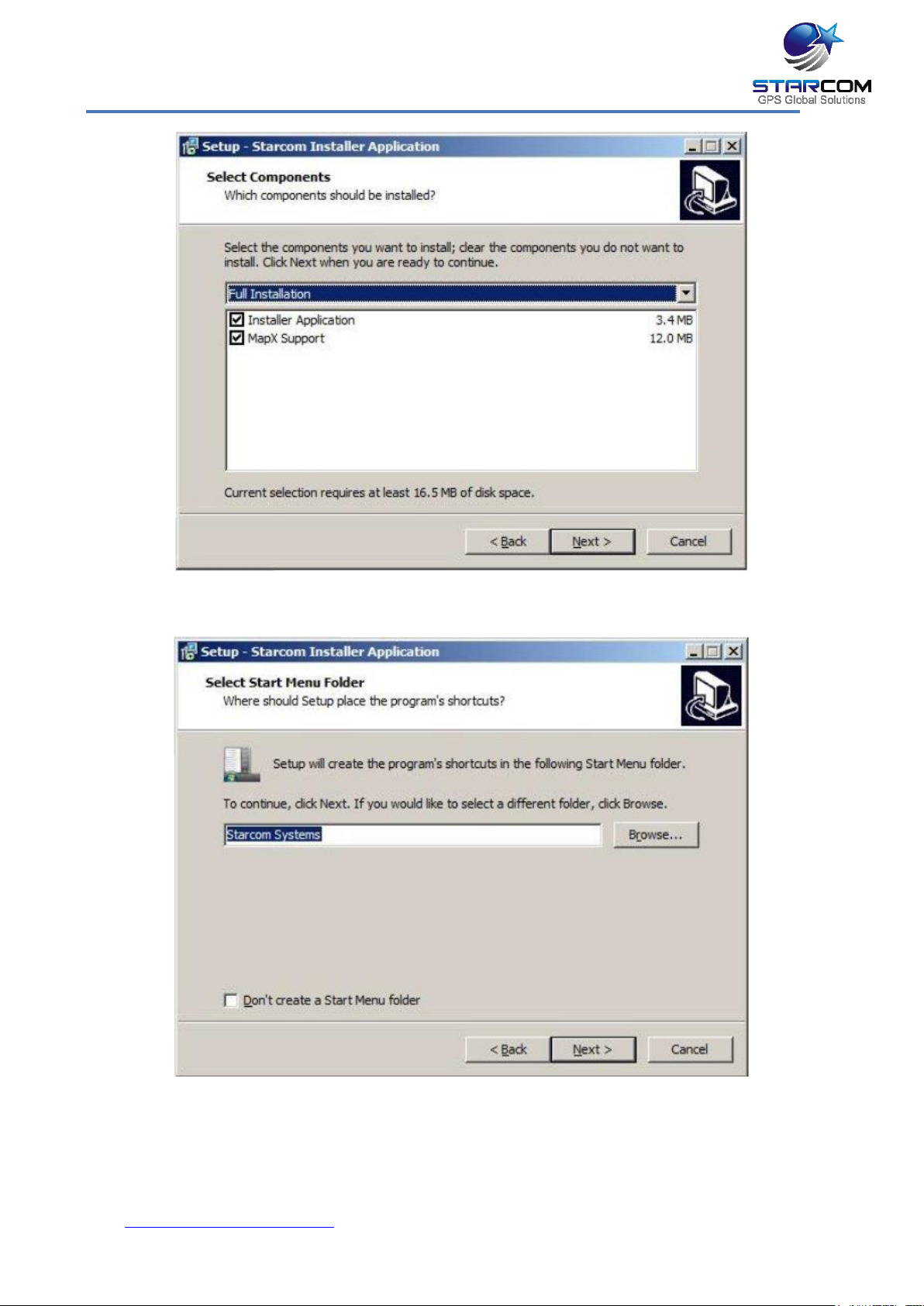
Click Next. The Select Destination Location window appears.
Click Next. The Select Components window appears.
www.starcomgpsglobal.com 20
Helios Users Guide
Click Next. The Select Start Menu Folder window appears.
NOTE: Select Don’t create a Start Menu folder checkbox, if you do not want
to create a start menu folder.
Click Next.
www.starcomgpsglobal.com 21
Helios Users Guide
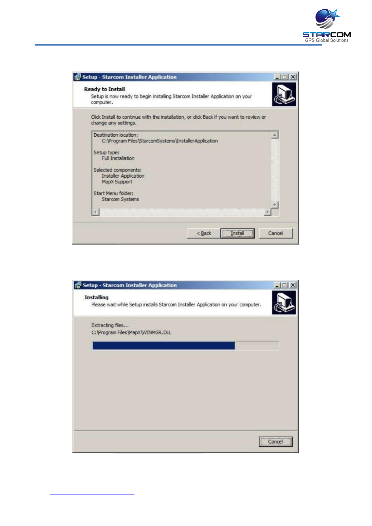
The Ready to install window appears.
Click Install. The installation starts and a progress bar appear in the window,
indicating the progress of the installation.
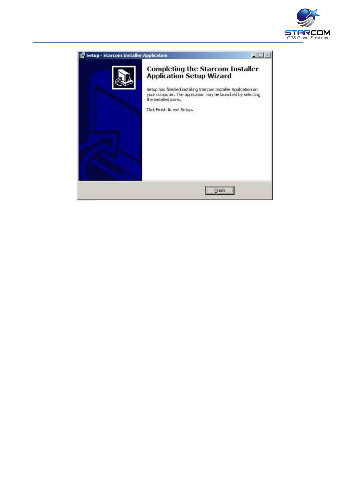
When the installation is complete, the Completing the Starcom Installer
Application Setup Wizard window appears.
www.starcomgpsglobal.com 22
Helios Users Guide
Click Finish.
www.starcomgpsglobal.com 23
Helios Users Guide
Installing the Update
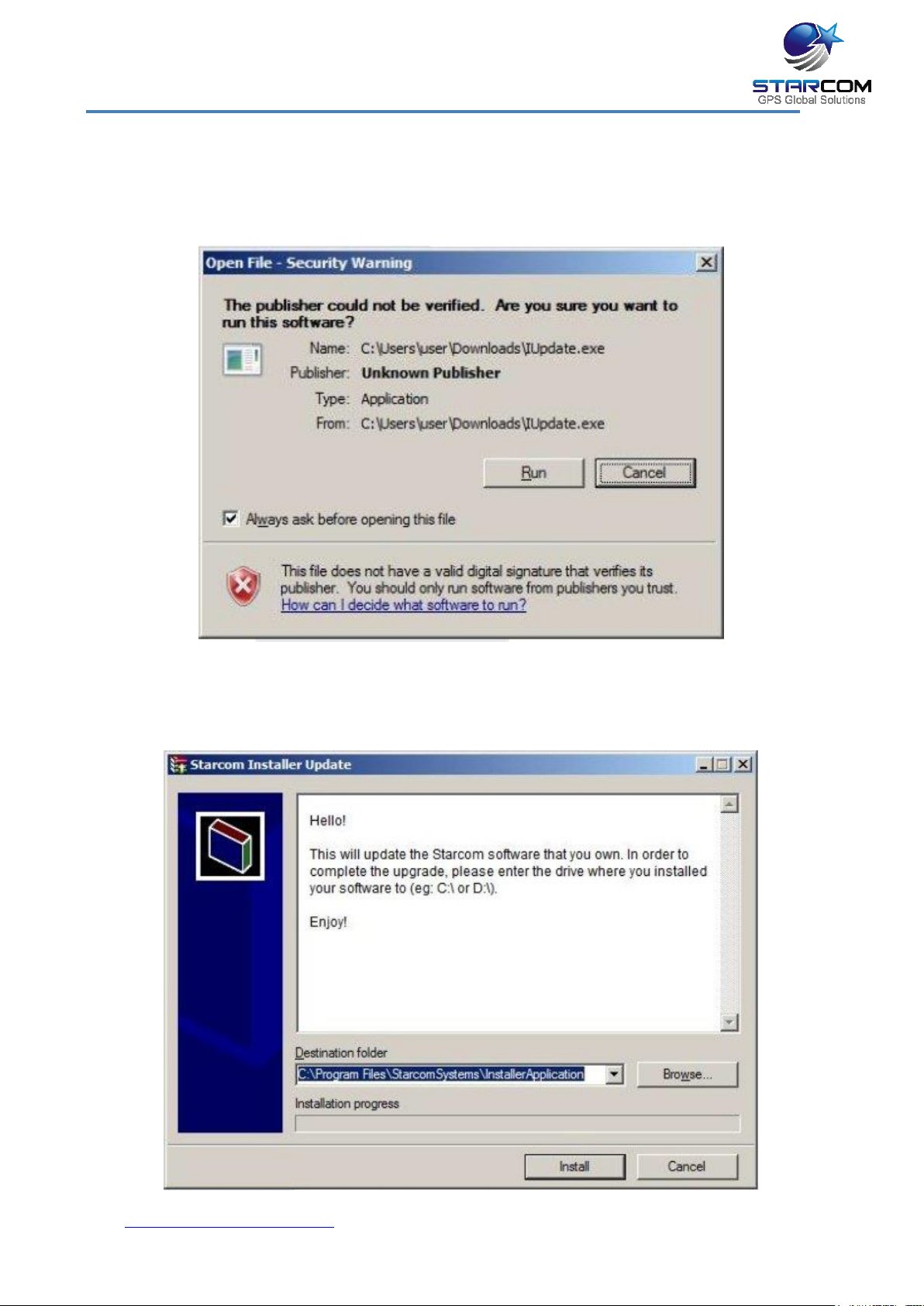
To install the Installer update software, locate the folder where you saved the
update file. Double-click IUpdate.exe. The Open File dialog box appears.
Click Run. The Starcom Installer Update window appears.
www.starcomgpsglobal.com 24
Helios Users Guide
Verify that the Destination folder points to the location where the Starcom
Installer software is installed and click install. A Windows Security dialog box
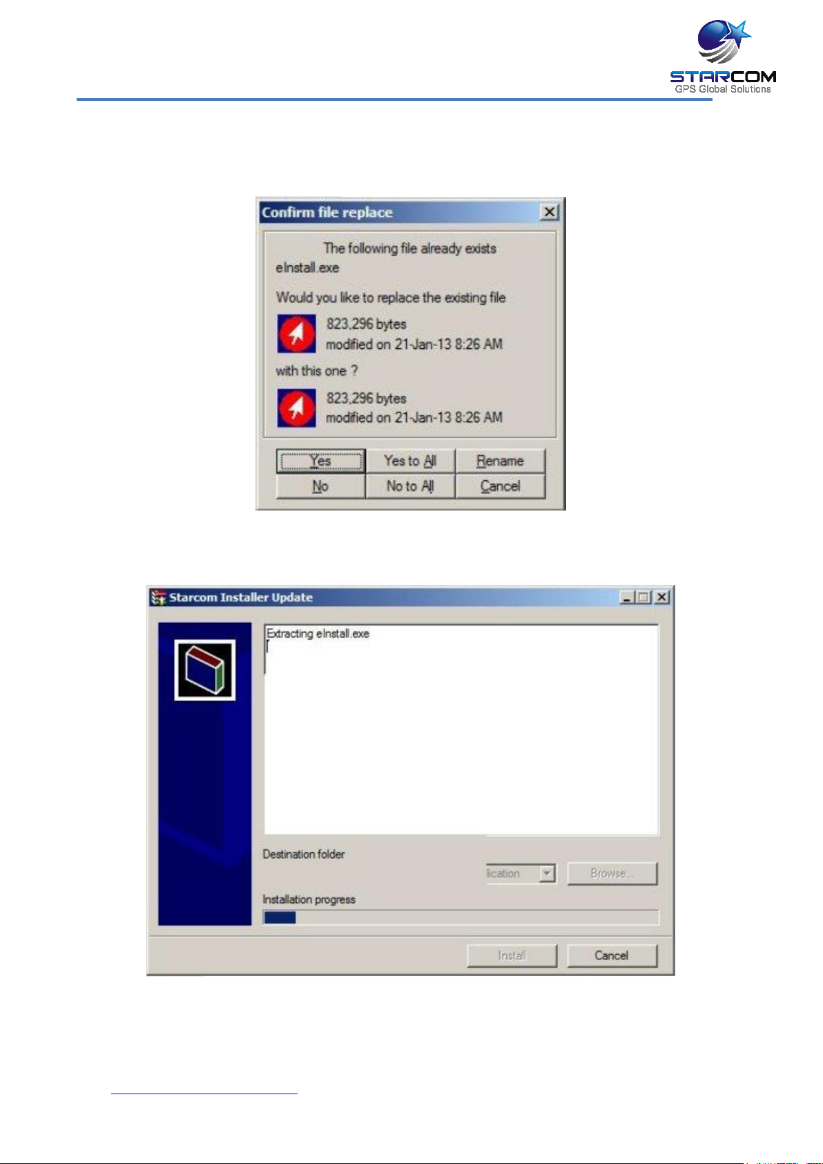
appears. Click Yes. The Confirm file replace dialog box appears.
Click, Yes to All. The installation starts and a progress bar appears in the
window, indicating the progress of the installation.
The Starcom Installer Update window closes, when the update is complete.
www.starcomgpsglobal.com 25
Helios Users Guide
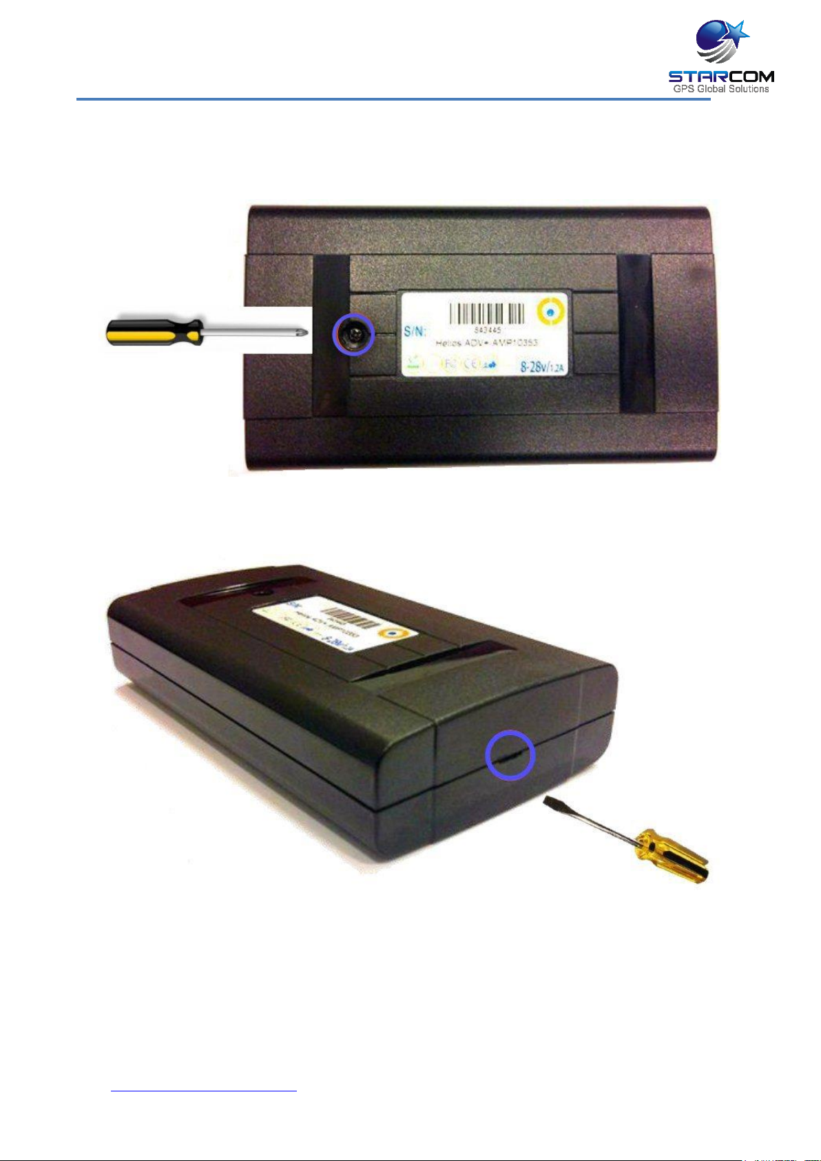
Inserting the SIM card
Use a small Phillips screwdriver to remove the screw from the bottom cover.
Insert a flat screwdriver in the slot between the unit covers. Carefully twist the
screwdriver to lift and open the unit cover.
Gently push and pull back the plastic SIM card holder to release and open the
SIM card slot. Raise it to an upright position.
www.starcomgpsglobal.com 26
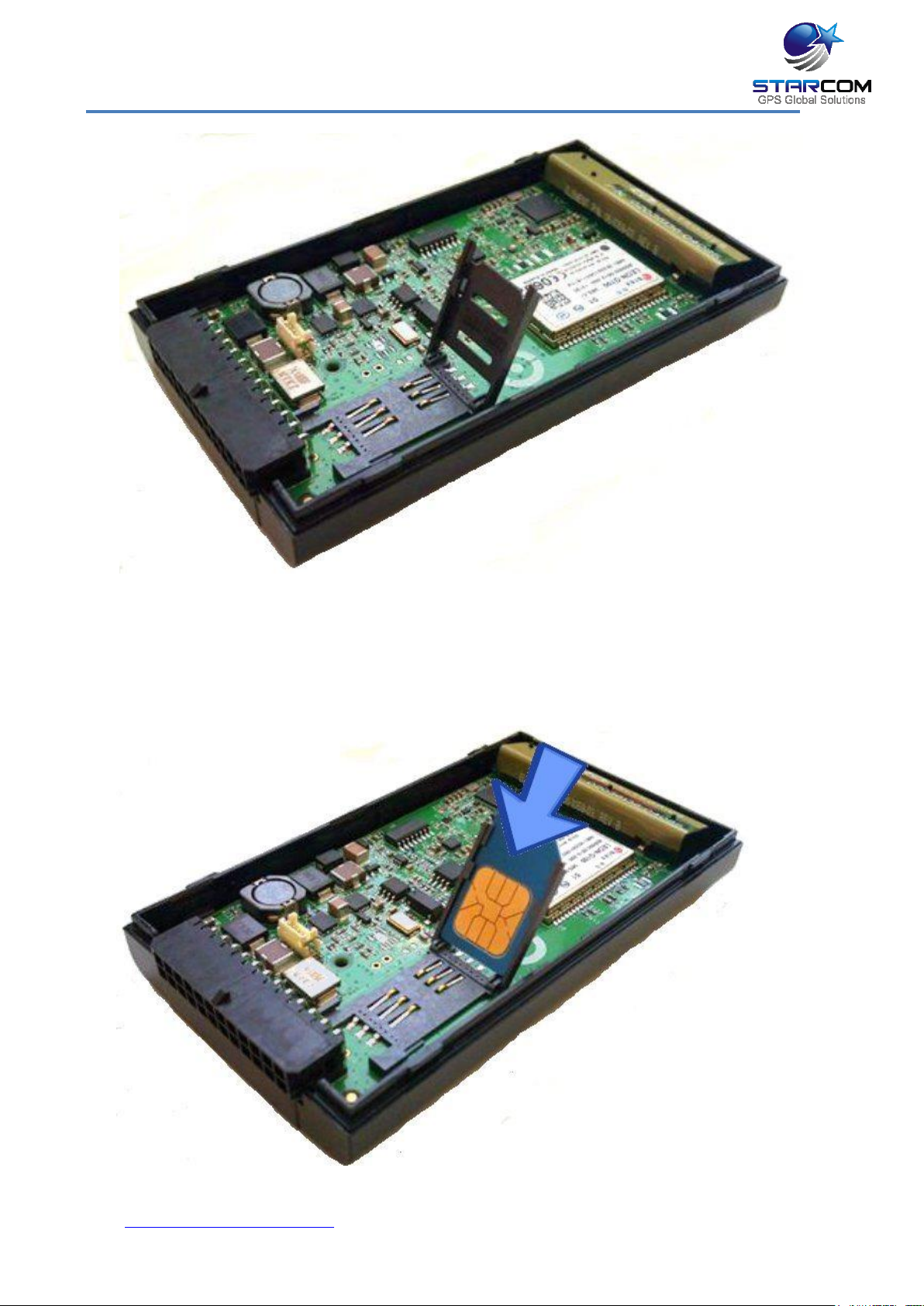
Helios Users Guide
Insert the SIM card in the SIM card slot with its gold contacts facing down and
its cut-off corner facing out the SIM card slot, as shown in the following image.
www.starcomgpsglobal.com 27
Helios Users Guide
Lower the SIM card holder back to the horizontal position. Gently press and
push the SIM card holder forward to snap it back into place.
www.starcomgpsglobal.com 28
Helios Users Guide
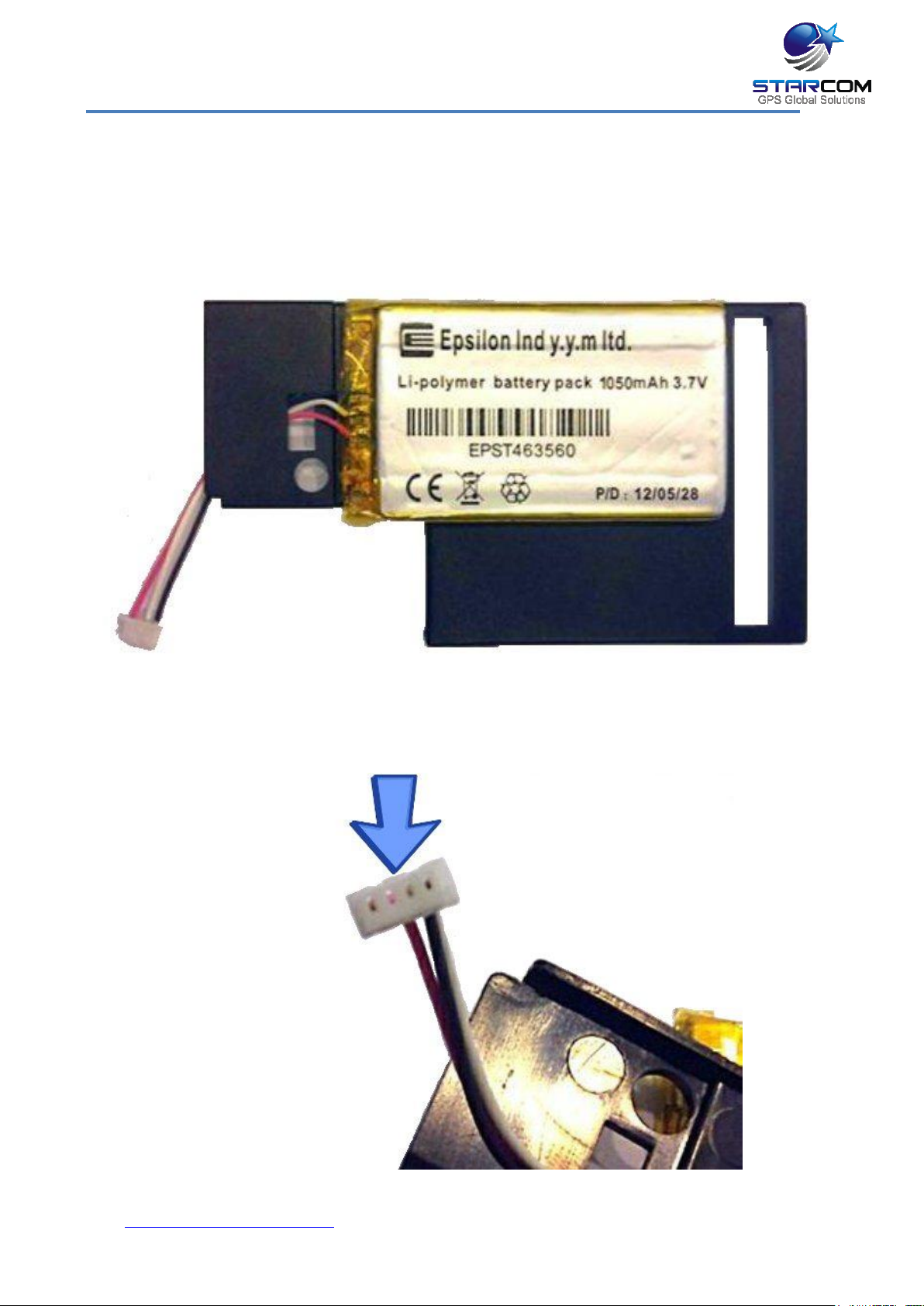
Attaching the battery (optional)
NOTE: Connecting the battery to the unit must be carried out very carefully.
Use caution to avoid causing damage to the battery and the unit.
Place the battery on the divider, as shown in the following image.
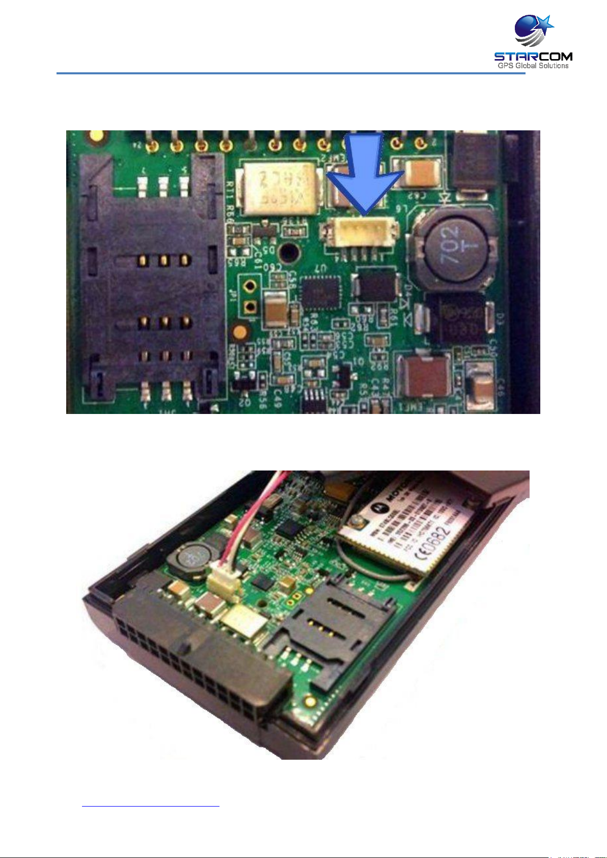
Verify that you’re connecting the battery connector to the connector on the unit
board correctly. The side of the battery connector with the pinholes located
closer to the edge
www.starcomgpsglobal.com 29
Helios Users Guide
must be connected to the corresponding side of the connector on the unit
board.
Carefully insert the battery connector into the connector on the unit.
www.starcomgpsglobal.com 30
 Loading...