

Starck NETATMO User Manual
2
Replacing a wireless thermostat
You can watch this installation at:
http://netatmo.com/video2
or installing your first thermostat
You can watch this installation at:
http://netatmo.com/video3
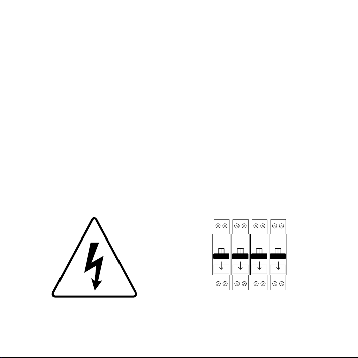
Warning!
• Read these instructions carefully before starting the installation.
• The Netatmo Thermostat must be installed according to
applicable standards.
• Before any intervention, make sure power is turned off.
• The Netatmo Thermostat cannot control electric converters.
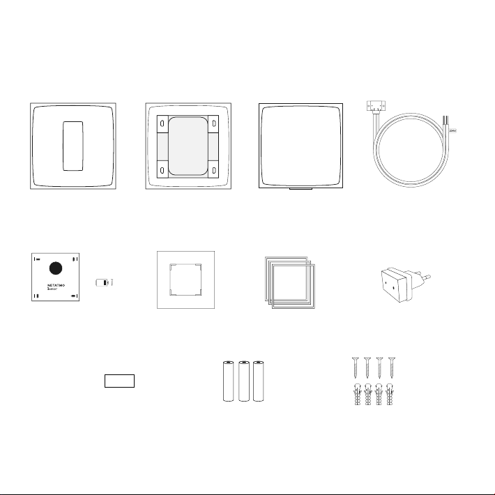
In the box
Tape
Mobile stand
(Trim plate)*
3 AAA batteries
* not used or optional in this setup
Color Adhesives
(Power Plug)*
4 screws
4 screw anchors
Thermostat Relay Boiler adapter
+
(Mounting Plate)*
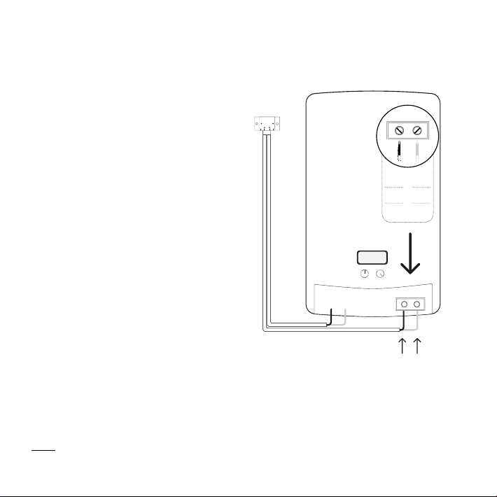
Wiring
Open the boiler door (use the
boiler manual, if necessary).
Identify the thermostat terminals in
the boiler, often labeled LS-LR, TA or
COM-NO. They may be identifiable
thanks to a shunt between the two
thermostat terminals.
If your are replacing a wireless thermostat, find your former thermostat’s
relay and remove it.
If you are installing your first thermostat, please remove the shunt between
the two thermostat terminals.
LS / LR
or
TA
or
COM / NO
Connect the black and grey wires
of the boiler adapter cable to the
thermostat terminals.
Note : Some thermostats are connected to dierent terminals from those on the diagram’s list (for
example, eBus, EMS…). In this case, you will have to identify the right thermostat terminals to connect the
Relay of the Netatmo Thermostat.
Thermostat terminals
Black and grey wires
No polarity
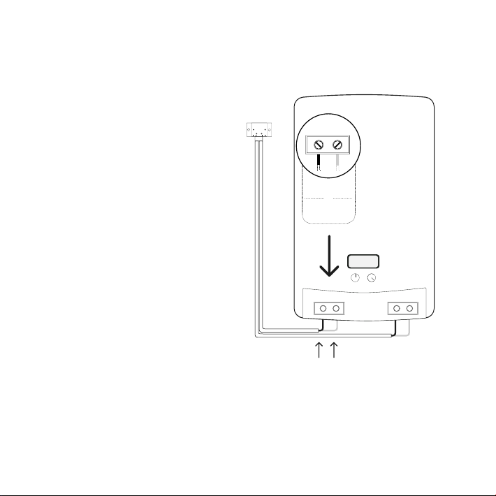
Wiring
Connect the blue and brown
wires of the boiler adapter
cable to the power supply
terminals (P/N or L/N).
Our forum can help you
identify where to plug the wires
in, at forum.netatmo.com.
In doubt, please send a picture
of your wiring to:
photo@netatmo.com
and our support team will help
you identify the right terminals.
P / N
or
L / N
230 V Power supply terminals
Blue and brown wires
 Loading...