


MANU-1072-HIN Rev. E
REBOKE 6000 TSI
Farming Wagon
Instruction Manual


STARA S/A - INDÚSTRIA DE IMPLEMENTOS AGRÍCOLAS
CNPJ: 91.495.499/0001-00
Av. Stara, 519 - Caixa Postal 53
Não-Me-Toque - RS - Brazil - CEP: 99470-000
Telephone/Fax: (0xx54) 3332-2800
e-mail: stara@stara.com.br
Home page: www.stara.com.br
MANU-1072-HIN
February/2016 - Revision E
REBOKE 6000 TSI
FARMING WAGON
INSTRUCTION MANUAL


CONTENT
FOREWORD .......................................................................................................................................7
INTRODUCTION ................................................................................................................................9
1 - MAIN COMPONENTS ................................................................................................................. 11
2 - IDENTIFICATION ........................................................................................................................12
3 - TECHNICAL SPECIFICATIONS .................................................................................................12
4 - DIMENSIONS ..............................................................................................................................14
5 - SAFETY PROCEDURE ...............................................................................................................15
5.1 - General safety procedures .................................................................................................. 15
5.2 - Understanding safety information ....................................................................................... 15
5.3 - Decal care............................................................................................................................16
5.4 - Intended use ........................................................................................................................ 16
5.5 - Improper operation ..............................................................................................................16
5.6 - Preventing unexpected machine start-up ........................................................................... 17
5.7 - Precautions to work with safety ...........................................................................................17
5.8 - Operating the implement with safety ...................................................................................18
5.9 - Safety measures transporting the implement .....................................................................20
5.9.1 - Transporting on public roadways ......................................................................................20
5.9.2 - Transporting the implement on trucks or shipping pallets ............................................... 20
5.9.3 - Lights and safety devices ................................................................................................. 20
5.10 - Avoid heating parts near uid lines ...................................................................................21
5.11 - Emergency procedures ......................................................................................................21
5.12 - Avoid uids under high pressure .......................................................................................21
5.13 - Clean water reservoir .........................................................................................................22
5.14 - Cautions while on hilly terrain ............................................................................................ 22
5.15 - Safety procedures for tires ................................................................................................22
5.16 - Safety measures during implement maintenance .............................................................23
5.17 - Protecting the environment ............................................................................................... 24
5.18 - Operator cautions when handling toxic products ..............................................................24
6 - MAINTENANCE ..........................................................................................................................25
6.1 - Retightening and lubrication ................................................................................................25
6.2 - Treatment system clean-up procedure ...............................................................................25
6.3 - Safety shields ......................................................................................................................26
6.4 - Main tank cares ...................................................................................................................27
6.5 - Paint care and cleaning ....................................................................................................... 27

7 - ASSEMBLY ..................................................................................................................................27
7.1 - Wheel assembly to axle installation ..................................................................................... 28
7.2 - Wheel axle to chassis installation .......................................................................................28
7.3 - Trailer hitch installation ........................................................................................................28
7.4 - Mounting the chassis, the main tank, support plate and chassis supports ........................29
7.5 - Mounting the cap, grating, the ladder and the canvas support arches ............................... 29
7.6 - Funnel installation ................................................................................................................29
7.7 - Support and the rest installation ..........................................................................................30
7.8 - Installing the 1
st
stage auger to the chassis.........................................................................30
7.9 - Mounting the output chute ...................................................................................................30
7.10 - Installing 2
nd
stage auger screw .........................................................................................31
7.11 - Mounting the clean water reservoir, treatment pumps, personal hygiene reservoir and
pump supports. ............................................................................................................................31
7.12 - Treatment control center installation .................................................................................. 31
7.13 - Hydraulic system installation .............................................................................................. 32
7.14 - Installing the treatment system ..........................................................................................32
7.15 - Independent hydraulic system installation .........................................................................32
7.16 - Tractor hook-up ..................................................................................................................33
7.17 - Convoy hook-up with the 14000 Plus/16000 Plus/11000 and 24000 ................................ 34
8 - OPERATION AND CALIBRATIONS ...........................................................................................34
8.1 - Procedures while maneuvering during the job ....................................................................34
8.2 - Independent hydraulic system operation ............................................................................35
8.3 - Seed treatments procedures ............................................................................................... 35
8.4 - Calibration procedures ........................................................................................................35
8.5 - Procedure to initiate the treatment ...................................................................................... 36
8.6 - Basic calibration tips for the treatment and graphite systems ............................................ 36
8.7 - Circuit cleaning procedure...................................................................................................37
9 - INTELLIGENT ELECTRONIC METERING SYSTEM ................................................................. 37
9.1 - Electronic metering system panel ........................................................................................ 37
9.2 - Functions .............................................................................................................................38
10 - METERING TROUBLESHOOTING ..........................................................................................40
11 - MULTIPLEX DL-128 MODULE PANEL ..................................................................................... 41
12 - INSTANT ELECTRONIC METERING SEED TREATMENT SYSTEM ..................................... 42
13 - SYSTEM TROUBLESHOOTING ...............................................................................................43
WARRANTY CLAIMS ......................................................................................................................45
WARRANTY REGISTRATION .........................................................................................................53

TECHNICAL DELIVERY TERMS .....................................................................................................57
TECHNICAL CHECK-UP TERMS .................................................................................................... 61


FOREWORD
This user manual was designed to guide you in the operation of your implement, its components,
and to instruct you on operation procedures and maintenance.
Read this manual thoroughly before using this product for the rst time, and make sure to take all
the necessary safety precautions.
This manual should be considered as a fundamental part and should be well cared for so that it is
always available for review since it contains instructions starting with the purchase of the implement
or machine to maintenance and long term care. At the end, there are also instructions on Warranty
Terms, Warranty Registration, Technical Delivery and Technical Check-up.
Due to the constant evolution of our products, Stara reserves the right to make changes to the
contents of this manual without prior notice.
This manual is available on our site www.stara.com.br, along with information on our entire product
line.


INTRODUCTION
Dear client, you have just become the proud owner of an implement made with the highest
technology, and which had the direct involvement of farming professionals who furnished their
inputs in its development.
The Reboke 6000 TSI has as its main feature, the ability to treat the seed in the eld, during the
re-lling process, thus reducing unnecessary seed handling. Also, the seed inoculation treatment
process has great benets in that the seed microorganisms have a longer life span, an additional
benet as it is placed in the soil shortly after the inoculation. Additionally, the Reboke 6000 TSI eld
treatment limits the waste of treated seed.
With proper use and a timely maintenance program, the Reboke 6000 TSI will further extend the
implement’s life expectancy, thus making it a highly protable investment. With that, we recommend
that you read this instruction manual carefully, and refer to it whenever there are questions and
doubts.
Stara makes available its technical assistance to help you and the dealership, in an effort to
maximize your implement’s protability.


Reboke 6000 TSI Instruction Manual
11
1 - MAIN COMPONENTS
The Reboke 6000 TSI farming wagon is made up of some basic components:
A - Chassis
B - Hitch
C - Drive-train
D - Grating
E - Canvas support arch
F - Main tank
G - Support
H - Ladder
I - Auger 1
st
stage
J - Auger 2
nd
stage
K - Treatment circuit
L - Clean water reservoir
M - Personal hygiene reservoir
Figure 1
I
J
A
D
E
F
M
C
G
K
L
K
H
B
Reboke 6000 TSI Instruction Manual
12
2 - IDENTIFICATION
All of Stara’s implements have and identication plate, which
lists the weight, capacity, model, manufactured date and serial
number.
When requesting parts or any information at your dealership,
mention the information which identies your implement.
The identication plate (Figure 2) is xed to the chassis of the
implement.
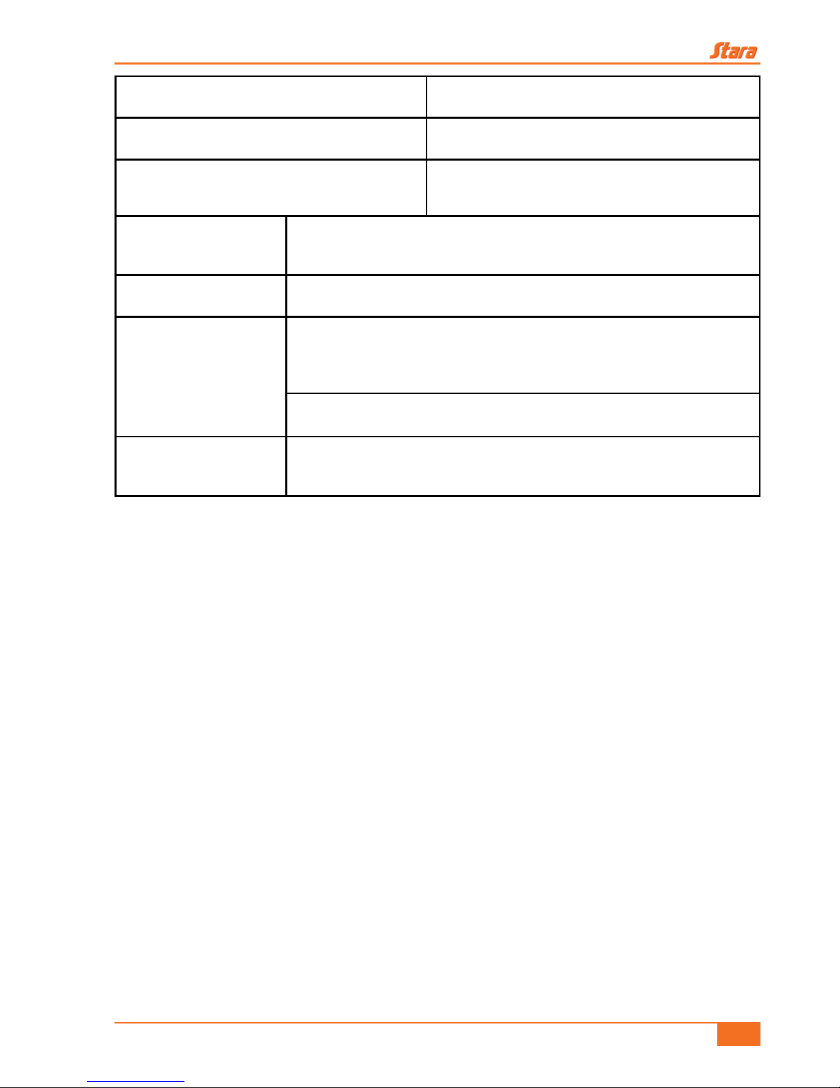
3 - TECHNICAL SPECIFICATIONS
Length with an auger 5.2 m
Length without an auger 3.4 m
Overall width of drive-train with an auger 5 m
Overall width of drive-train 2.7 m
Height with a closed auger 3.3 m
Height with an open auger 4.3 m
Auger output work height 3.7 m
Base raw material
Main tank Polyethylene
Chassis, output
chute and slidegate
Carbon steel
Seed treatment capacity 150 kg/min
Treatment pumping capacity 35 l
Minimum tractor pump ow-rate 50 l/min
Inoculant dosage range 80 to 700 ml
Pesticide dosage range 200 to 2000 ml
Treatment types Liquid inoculates, pesticides and graphite
Figure 2
Reboke 6000 TSI Instruction Manual
13
Minimum tractor power requirement 75 hp
Auger and feeder belt drive system TE 65 motor with electro-hydraulic controls.
Treatment system Remote controlled, electronic RPM sensor control
Hydraulic system
Electric system
Two helical pumps with reduction motors; Directional valves controller;
Inoculant and pesticide agitators; Graphite applicator with mixer.
Tires 7.50 x 16” - 10 Ply
Optional
Independent hydraulic system:
Oil reservoir with 110 liter capacity and a pump with output rate of 50 l/
min, PTO driven shaft at 540 rpm.
Convoy hitch
SHS oil system
(optional)
ST OIL ISO 68
Table 1
Reboke 6000 TSI Instruction Manual
14
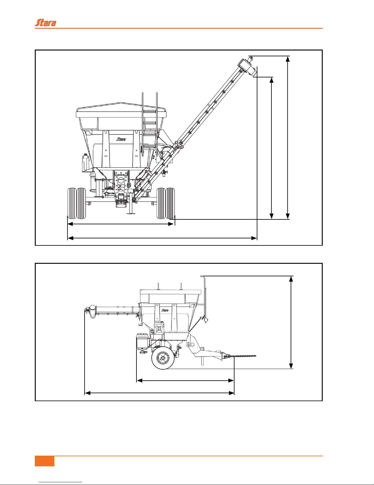
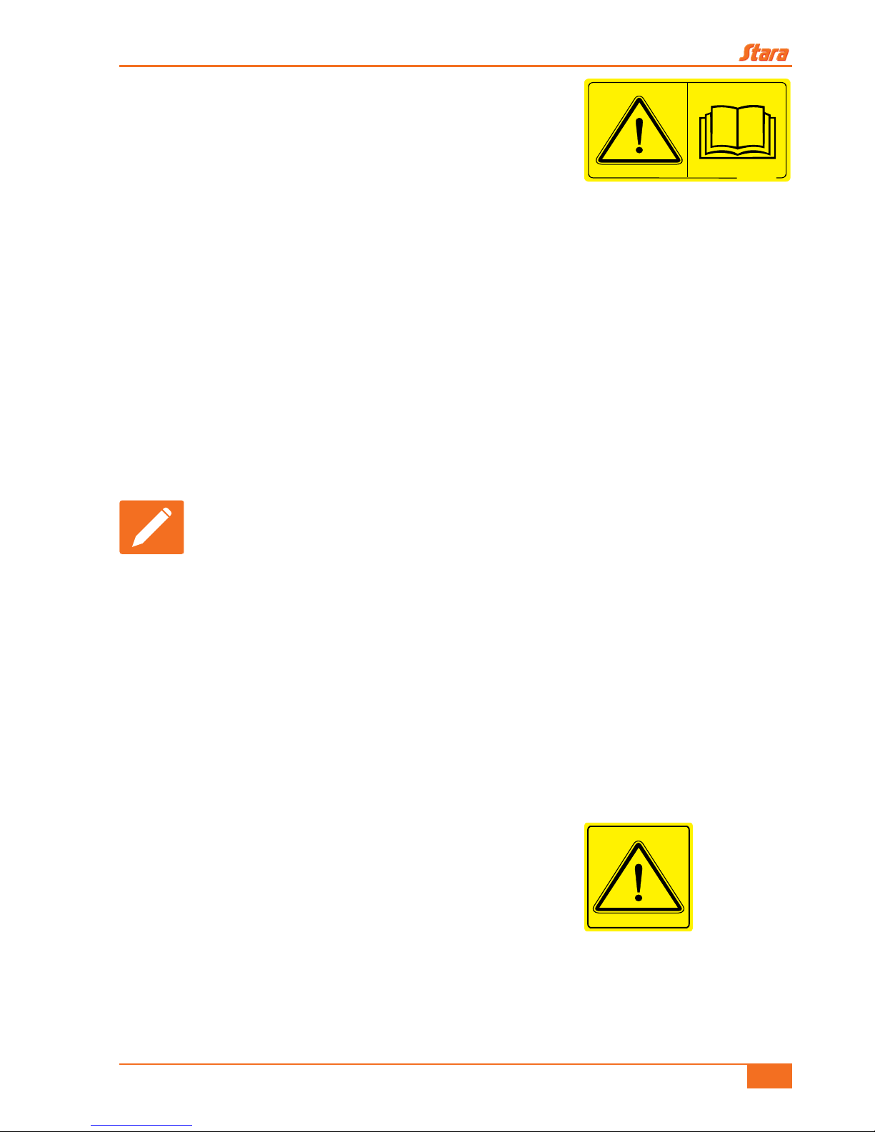
4 - DIMENSIONS
Figure 3
2.7 m
5 m
4.3 m
3.7 m
3.3 m
3.4 m
5.2 m
Figure 4
Reboke 6000 TSI Instruction Manual
15
5 - SAFETY PROCEDURE
The following items will describe the importance of operator
safety, also clarifying common risk situations during normal use
and implement maintenance, suggesting possible actions during
these situations.
Precautions are necessary in light of the equipment being used and working conditions found in the
eld, or in maintenance areas. The manufacturer has no direct control regarding these precautions
thus it becomes the responsibility of the owner to enforce these safety procedures while working
with the implement.
This implement follows design and work related SAFETY POLICIES FOR MACHINERY
EQUIPMENT CONSTRUCTION per NR-12.
Changing the original design of the implement is not allowed, since any alterations could affect the
operation of the implement, its safety and could reduce its lifespan.
Should you not fully understand any part of this manual and need the assistance of a technician,
please contact your local Stara dealership.
Carefully read all safety related messages and warnings in your manual (Figure 5).
IMPORTANT!
Maintain this instruction manual in good condition and do not forget to consult
it on a regular basis.
5.1 - General safety procedures
• When inspecting and refueling or relling other materials, all should be done with the implement
turned off and parked, using all safe means of accessibility.
• It is forbidden to carry passengers on self-propelled machines and implements.
• When servicing or inspecting the implement in high risk areas, these should only be done by
trained or skilled workers, when dealing with security issues
5.2 - Understanding safety information
This symbol is used as a warning sign (danger, warning and
caution). When you see this sign on your implement, be aware of
possible hazards (Figure 6).
Follow all recommended safety precautions and operational
safety practices, understand the importance of your safety.
• Accidents can cripple you, even cause death.
• Accidents can be prevented.
9100-6207
Figure 5
Figure 6
Reboke 6000 TSI Instruction Manual
16
5.3 - Decal care
• Do not remove or disgure safety or job instruction decals.
• Maintain safety decals in good condition.
• Replace any damaged or missing decals.
• Replacement safety decals can be found at your local Stara dealership.
5.4 - Intended use
• This implement was specically designed to be used with grains, seeds, fertilizers or in seed
treatments.
• This implement should be driven and operated by a trained operator.
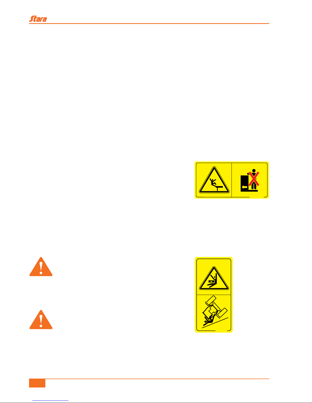
5.5 - Improper operation
• To avoid the risk of injuries or death, do not transport
passengers or objects on the catwalk or on any part of the
implement (Figure 7).
• Do not use the tank or the output system of the implement
with other then specied products.
• Hitching-up, hooking-up or pushing other implements or accessories is not allowed.
• The implement should only be used by qualied operators who knows all controls and operation
techniques.
WARNING!
Any improper use of the implement, specially
on irregular terrain or hilly terrain could cause
overturning of the implement. Be extremely
cautious during rain, snow, icing or any slippery
terrain. If necessary get off the machine and
check the consistency of the soil.
WARNING!
Never leave the machine while it is in motion,
even if it is overturning, or suffer the possibility
of being crushed.
9100-6208
Figure 7
9100-5905
Figure 8
Reboke 6000 TSI Instruction Manual
17
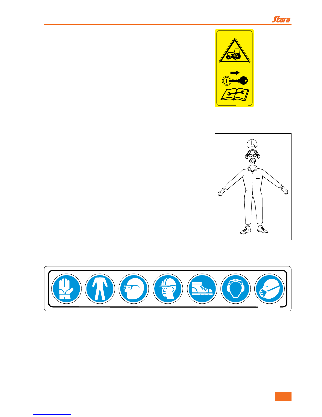
5.6 - Preventing unexpected machine start-up
• Protect yourself against possible injuries and even death, due
to an unexpected machine start-up.
• Do not start the tractor if the implement is not properly hitched
(Figure 9).
5.7 - Precautions to work with safety
When performing certain procedures with the implement, use the
required safety equipment as listed below (Figure 10 and Figure
11).
• Waterproof gloves;
• Waterproof long sleeve overalls;
• Safety glasses;
• Hard hat;
• Waterproof steel toe safety shoes;
• Hearing protection;
• Safety breathing mask with appropriate lter.
9100-5911
Figure 9
Figure 10
9100-6958
Figure 11
Reboke 6000 TSI Instruction Manual
18
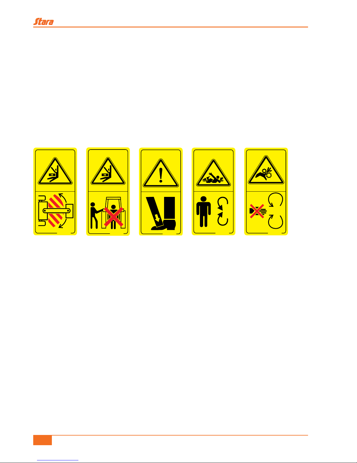
5.8 - Operating the implement with safety
• Learn how to properly operate the implement.
• Do not allow untrained persons to operate the implement.
• Maintain the area of movement free while the implement is in operation (Figure 12).
• Before operating the implement, check for any persons or obstructions nearby (Figure 13).
• When using the jack or support stand, take care of possible accident hazards (Figure 14).
• Stay clear of mechanical moving parts like augers, gears and belts (Figure 15 and Figure 16).
• Periodically inspect all safety equipment on the implement before using it.
• Operate the implement only when all safety shields are properly installed and in their proper
positions.
• Do not operate near obstacles, rivers or streams.
• Before unhitching the wagon from the tractor, be sure to place stop blocks under the tires.
• Drive with caution and slowly while on rugged and hilly terrain.
• When going down-hill with the implement, use the same gears used while climbing (braking
motor).
• Restricted access for maintenance only, which should be done by specialized personnel who
will be accessing this area, and it is mandatory that all drive systems be disconnected.
• For greater implement safety and useful life, avoid heavy loads greater then the nominal
capacity specied for each implement.
• Use a tractor properly sized for the power requirements and, counterweights compatible with
the load and topography of the terrain, so that the tractor can safely control the implement.
Verify the minimum power requirements recommended for each implement model.
9100-5781
Figure 12
9100-5783
Figure 13
9100-5784
Figure 14
9100-5900
Figure 15
9100-5882
Figure 16
Reboke 6000 TSI Instruction Manual
19
• Reduce speed on curves.
• When climbing on the implement, use the anti-skid steps on the ladder. Keep all steps, hand-
rails and catwalks free of residues like oil or grease, which could cause accidents (Figure 17).
• When covering the wagon with its canvas covering, avoid walking on the edges of the tank and
make use of the ladder, thus you will limit any accidental falling hazards.
• In case there is a need to enter the implement’s tank, use the ladder.
• Check the implement for proper working conditions. In case of any irregularities which may
hamper the operations, order the proper maintenance corrections prior to the operating or
transporting.
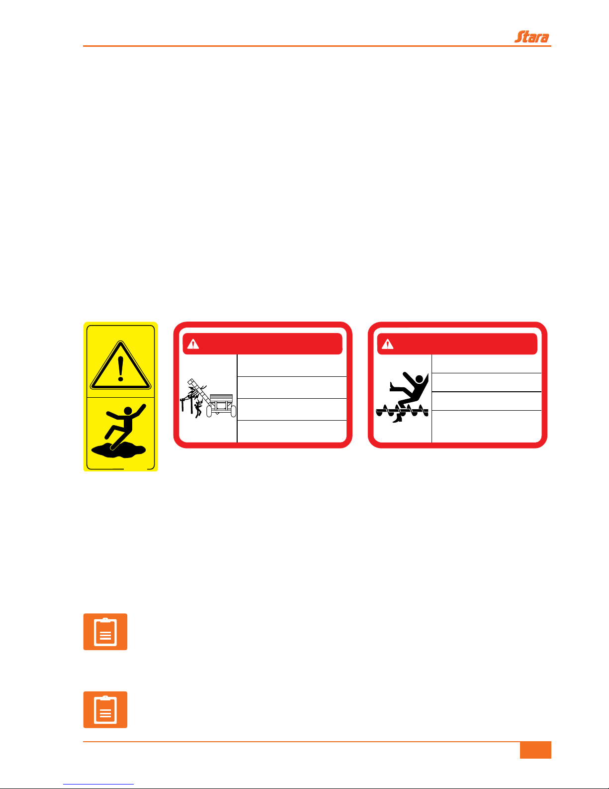
• Before operating the implement check the surrounding job area. Check for any nearby
obstructions like, trees, fences and high power electrical lines which are sources to serious
injury or even fatal hazards (Figure 18).
• Entering the tank area during use is prohibited. Access is allowed only for maintenance
servicing, while using safety rigging attached to the platform (Figure 19).
• When driving, drive at speeds compatible with the terrain and never above 16 km/h, thus you will
protect the implement by reducing maintenance costs and increasing its useful life.
• Reduce speed on wet or frozen surfaces or surfaces covered with gravel.
• Do not operate under the inuence of alcohol, tranquilizers or stimulants.
• Do not pick-up hitchhikers.
NOTE!
The optional rear hydraulic braking system has been sized only to assist the
tractor in the eld when controlling the tractor/wagon package on rough and
hilly terrain. It should not be used as the only braking device when the wagon
is loaded.
NOTE!
Before transporting the wagon, check that the output-chute is secure on its rest,
thus keeping the auger screw from dislodging and possibly cause and accident.
9100-6957
Figure 17
NÃO SE APROXIME DE LINHAS DE TRANSMISSÃO
OU CABOS ENERGIZADOS. O CHOQUE ELÉTRICO
PODE OCORRER COM OU SEM CONTATO DIRETO.
NO SE ACERQUE DE LÍNEAS DE TRANSMISIÓN O
CABLES ENERGIZADOS, EL CHOQUE ELÉCTRICO
PUEDE OCURRIR CON O SIN CONTACTO DIRECTO.
STAY CLEAR OF TRANMISSION LINES OR POWER
LINES, ELECTRIC SHOCK MAY OCCUR WITH OR
WITHOUT DIRECT CONTACT.
НЕ ПРИБЛИЖАЙТЕСЬ КЛИНИИ ПЕРЕДАЧ ИЛИ
ЭЛЕКТРИЧЕСКИМПРОВОДАМ, ПОРАЖЕНИЕ
ЭЛЕКТРИЧЕСКИМТОКОМ МОЖЕТПРОИЗОЙТИ
ПРИ НЕПОСРЕДСТВЕННОМ КОНТАКТЕ ИЛИ БЕЗ НЕГО.
9100-6963
PERIGO / PELIGRO / DANGER / ОПАСНОСТЬ
Figure 18
PROIBIDO O ACESSO AO RESERVATÓRIO
DURANTE O USO!
ACESSO SOMENTE PARAMANUTENÇÃO!
9100-8660
RESERVOIR ENTRY PROHIBITED
DURING OPERATION!
ENTRY ALLOWED DURING MAINTENANCE ONLY!
¡PROHIBIDO EL ACCESOAL ESTANQUE
DURANTE EL USO!
¡ACCESO SOLAMENTE PARAMANUTENCIÓN
ЗАПРЕЩЕНОНАХОДИТСЯ ВНУТРИ
БУНКЕРА-НАКОПИТЕЛЯ ПРИ РАБОТЕ ОБОРУДОВАНИЯ
НАХОДИТСЯ ВНУТРИБУНКЕРА-НАКОПИТЕЛЯ
РАЗРЕШЕНО ТОЛЬКОПРИ ВЫКЛЮЧЕННОМ
ОБОРУДОВАНИИСЦЕЛЬЮ ТЕХОБСЛУЖИВАНИЯ
PERIGO / PELIGRO / DANGER /ОПАСНОСТЬ
Figure 19

Reboke 6000 TSI Instruction Manual
20
5.9 - Safety measures transporting the implement
5.9.1 - Transporting on public roadways
• Traveling with the implement on public roads is prohibited.
• Know and respect all trafc signs.
• When transporting the implement use great caution.
• Do not obstruct trafc lanes.
5.9.2 - Transporting the implement on trucks or shipping pallets
• The implement should be partially disassembled.
• Properly position the implement so that none of its parts stick outside the atbed area.
• Use chains to tie-down the implement to the atbed by its tires with blocks, applying the
implement’s own brakes.
• The implement’s chassis should be tied-down the truck body frame, using heavy-duty straps.
• Maintain the parking brake applied.
• Be aware of the implement’s height limitations. Be careful when driving near trees, power lines
and overpasses.
5.9.3 - Lights and safety devices
When transporting implement on public highways, use extreme caution and safety, follow all transit
and local laws.
• Frequently check rear view mirrors.
• Always use your turn-signals to indicate your turning direction.
• The safety beacon should be located on top of the cabin and turned-on.
• Use driving lights, warning signals and turn-signals when driving, day or night.
• Respect all trafc signs.
• Always maintain warning signals, headlights and reectors clean, so that they may always be
visible. Also, check that headlights, turn-signals and warning signals are all working properly
should they not be functioning properly, call a repair technician to x them.
• Use anti-skid steps and hand-rails, thus avoiding slipping on catwalks or ladders.
• Besides all these safety features, plus having a skilled and capable operator, these will increase
the safety factor of personnel in surrounding area.

Reboke 6000 TSI Instruction Manual
21
5.10 - Avoid heating parts near uid lines
The heat on the lines may cause the material to become brittle
and to rupture, releasing pressurized uid. This may cause
severe burns or injuries.
5.11 - Emergency procedures
• Always be prepared for any type of res.
• In case of a re, or any other hazardous situation detrimental to the operator, he should seek
shelter in a secure place as quickly as possible.
• Keep all emergency phone numbers like doctors, ambulance services, hospitals and re
department near your phone.
5.12 - Avoid uids under high pressure
• High pressure uid leaks can penetrate the skin, which could
cause severe injuries.
• Avoid such hazards by relieving the pressure prior to
disconnecting the hydraulic lines or other lines. Tighten all
connections prior to pressuring-up the system.
• Protect yourself against high pressure uids.
• In case of an accident, seek immediate medical attention. Any
uid that penetrates the skin needs to be surgically removed
within a few hours so that gangrene will not set in.
• Do not loosen hydraulic hoses while under pressure. Take great care when servicing the
hydraulic system and use your personal safety equipment like, gloves and safety glasses.
• Only the qualied technicians can x this type of system. Consult with your local Stara dealership.
Figure 20
9100-5785
Figure 21

Reboke 6000 TSI Instruction Manual
22
5.13 - Clean water reservoir
Supplies a clean water source for eld wash-down in case of
an emergency when dealing with chemical products. Should
you come into contact with these chemicals, wash-up and seek
immediate medical assistance.
WARNING!
This water is not safe for human consumption.
5.14 - Cautions while on hilly terrain
• Avoid holes, ditches and obstacles which could overturn the implement, specially on steep hills.
• Avoid tight curves on sloppy or hilly terrain.
• Never operate the implement near ditches or rivers, which could be prone to overturning.
• Stay away for steep hills which could increase uneven cutting, along with hampering the safe
operation of the implement, even causing overturning.
5.15 - Safety procedures for tires
• Never try to rell a tire which is completely at. If the tire has
lost complete pressure, contact the nearest tire specialist.
• Always try to use a protective cage or safety shield when
trying to ll a tire (Figure 25).
• In case of a punctured tire, deate it to remove the object responsible for the puncture. The work
9100-5763
Figure 22
PAREA MÁQUINA EM LOCAL SEGURO. NÃO ESTACIONE A
MÁQUINA EM ACLIVE OU DECLIVE.
9100-6959
PARK THE MACHINE INA SECURE PLACE.
DO NOT PARK ONASLOPE OR GRADE.
PARALA MÁQUINA EN LOCAL SEGURO.
NO APARQUE LAMÁQUINA EN ACLIVE O DECLIVE.
УСТАНАВЛИВАЙТЕ МАШИНУВБЕЗОПАСНОМ МЕСТЕ.
НЕ ПАРКУЙТЕ ЕЕ НА СКЛОНЕ ИЛИ ПОДУГЛОМ.
PERIGO / PELIGRO / DANGER /ОПАСНОСТЬ
Figure 23
AO EFETUAR A DESCARGADA REBOKE,VERIFIQUE SE A
MESMA ESTÁ ESTACIONADAEM TERRENO NIVELADO.
CASO O MESMO POSSUA ALGUMAINCLINAÇÃO, O TUBO DE
DESCARGA DEVE ESTAR VOLTADO PARA O LADO DO ACLIVE.
AO EFETUAR A DESCARGADA REBOKE,VERIFIQUE SE A
MESMA ESTÁ ESTACIONADAEM TERRENO NIVELADO.
CASO O MESMO POSSUA ALGUMAINCLINAÇÃO, O TUBO DE
DESCARGA DEVE ESTAR VOLTADO PARA O LADO DO ACLIVE.
9100-6962
WHEN UNLOADING THE TRAILER WAGON,VERIFY THATIT
IS PARKED ON LEVELTERRAIN. IF IT IS ON A SLOPE, THE
DISCHARGE CHUTE TUBE SHOULD BE TURNED TOWARD
THE SLOPE.
AL EFECTÚAR LA DESCARGADE LA REBOKE, VERIFIQUE SI
LA MISMA ESTÁAPARCADA EN TERRENO NIVELADO.
SI EL MISMO TENGAALGUNAINCLINACIÓN, ELTUBO DE
DESCARGA DEBE DE ESTAR VUELTO PARAEL LADO DELACLIVE.
ПРИ РАЗГРУЗКЕ БУНКЕРА-НАКОПИТЕЛЯ, УБЕДИТЕСЬ,
ЧТООНСТОИТ НА РОВНОЙ МЕСТНОСТИ.ЕСЛ ИОН
НАХОДИТСЯ НА СКЛОНЕ,РАЗГРУЗОЧНЫЙ ЖЕЛОБ
ДОЛЖЕН БЫТЬ ПОВЕРНУТКСКЛОНУ.
PERIGO / PELIGRO / DANGER / ОПАСНОСТЬ
Figure 24
Figure 25

Reboke 6000 TSI Instruction Manual
23
to dismount and remount the tire should be done solely by a qualied professional.
• Any changes to the rim balancing can cause the tire to explode. For that reason, dismount the
tire before making any repairs to the rim.
Instructions when inating a tire:
• Use an appropriate air hose, long enough to reach work area, having an air gun with a dual
valve and an incremental metering scale with which to measure and see the pressure reading.
• Place yourself behind the specied safety line, along with any other personnel before beginning
to inate the tire.
• Never inate the tire to pressures higher then specied.
5.16 - Safety measures during implement maintenance
• Before using or servicing the implement (Figure 26), review
the manual instructions of section 6 on page 25.
• In order for someone to operate your implement and
equipment, the operator should be capable, properly trained
and must have read the instructions contained in this manual.
• Always maintain the implement in good working conditions,
performing all required maintenances as dened by the type
and frequency of implement operation, and also the types of
products involved.
• Check for any signs of ware and tare, noises and any places where there is a lack of lubrication.
In case of a break-down or component failure, seek your dealership in order to replace the part
with an original one.
• After any servicing, re-install all safety shields and tighten all hardware.
• It is recommended that all maintenance services be performed by trained and capable
professionals, having all implement mechanical devices turned-off.
• Maintain all components like, hoses, connections and clamps in good working conditions, in
order to prevent leaks.
• While performing any maintenance on the implement, immediately clean-up any oil spills.
• Do not smoke, nor install any electrical equipment near ammable products, be it on the
implement or storage areas.
• Failure to perform proper maintenance and or the improper operation of the implement
by untrained personnel, can cause serious accidents and injuries, besides damaging the
implement.
• Maintain the work area clean and dry.
9100-5897
Figure 26

Reboke 6000 TSI Instruction Manual
24
• Before doing any maintenance or adjustments, turn-off all power sources (electric, hydraulic),
turn-off the equipment’s main engine and operate controls to relieve any built-up hydraulic
system pressures.
• After using the implement wash-it, thus extending its useful life.
• Whenever you perform maintenance, be sure to use all personal safety equipment (PPEs), as
mentioned in the manual (Figure 11).
5.17 - Protecting the environment
It is illegal to pollute channels, rivers or the soil. Improper waste
disposal is a threat to the environment and the ecology.
• Use containers to dispose used oils.
• Use leak and spill proof containers, when draining used uids.
• Do not dump waste on the soil, sewer systems and waterways.
In order to know the proper manner to recycle or to dispose of waste, which are the correct methods
to discard oils, lters, tires and electronic equipment, seek your local waste recycling center or your
local Stara dealership.
5.18 - Operator cautions when handling toxic
products
The Health Department Agency of Brazil, has subdivided
toxic products into four groups. These classications are
fundamental in understanding the toxicity of a product,
and their acute side effects. See below the toxicological
classes and their respective identifying colors which are
placed on their containers.
CLASS I Extremely toxic Red band
CLASS II Highly toxic Yellow band
CLASS III Moderately toxic Blue band
CLASS IV Low toxicity Green band
Figure 27
PRODUTOS TÓXICOS
TOXIC PRODUCTS
PRODUCTOS TÓXICOS
ТОКСИЧНЫЕ ВЕЩЕСТВА
UTILIZE EQUIPAMENTOS DE SEGURANÇA
ADEQUADOS PARA O MANUSEIO.
UTILICE EQUIPOS DE SEGURIDAD
ADECUADOS PARA ELMANOSEO.
DURING HANDLING, USE APPROPRIATE
SAFETY EQUIPAMENT.
ВО ВРЕМЯ РАБОТЫ, ИСПОЛЬЗОВАТЬ
СООТВЕТСТВУЮЩЕЕ ОБОРУДОВАНИЕ
ДЛЯ БЕЗОПАСНОСТИ.
9100-4725
Figure 28
Table 2

Reboke 6000 TSI Instruction Manual
25
6 - MAINTENANCE
6.1 - Retightening and lubrication
When you start to use the wagon, be sure to do a general inspection of all hardware, especially
paying attention to the wheel screws, hitch bar and the auger screw support.
After the rst two working hours, check all hardware tightness and retighten if necessary. In the
future adopt a procedure to periodically inspect (daily) the hardware while in use, always paying
attention to the wheels and hitching bar hardware.
While in use, daily inspect all hardware (wheel assemblies, axles, brackets, chassis/hitch
assemblies, bearing xtures) and, tighten as needed.
Grease daily all points where there is some form of friction between components. All grease joints
are dened by decals found on the implement. Grease the bearing xtures of the auger screw every
eight working hours. Use blue grease, specic to bearings.
Do not remove excess grease which forms during lubrication, since it is an excellent barrier against
dirt and water.
Maintain tires calibrated, periodically inspecting them, knowing that the maximum indicated
implement load is of 102 psi.
After nishing the work day, washout the treatment system using the water in the clean water tank.
When washing down the Reboke, do not allow for direct water contact with boxes which house the
electronic systems, doing so could damage components.
6.2 - Treatment system clean-up procedure
NOTE!
Clean-out the insides of the tube after use, any product built-up can lock-up the
springs.
The treatment system should be cleaned-out after the last treatment of the day, doing so will avoid
plugging up the system, just follow these steps:
• 1
st
- Drain the pesticide and inoculant reservoirs so that you can use them later on again.
• 2nd - Open the clean water valves and using their own pumps perform the rst system wash-
down, leaving extra water for a second wash-down.
NOTE!
The wash-down water can be recycled on the next solution batch mixture.

Reboke 6000 TSI Instruction Manual
26
6.3 - Safety shields
Do not operate the implement if any safety shields
are not in their proper places. The absence of
any safety shields can lead to serious hazards to
the implement’s operator.
The safety shields which are illustrated on
gures should always be removed with the
implement turned-off and only when performing
maintenance, during partial or full hook-up
assembly replacements, or during the cleaning
of the auger screw (C) (Figure 33).
To remove the shields, rst remove the screws (B) that hold the shields (A) (Figure 32) in place,
and after completing the maintenance, replace the shields to their proper places and reinstall the
screws.
Figure 29
SAFETY SHIELD
INSIDE FUNNEL
Figure 30
PROTECTIVE
GRATING
Figure 32
Figure 31
PROTECTIVE
BOX
Figure 33
A
B
C

Reboke 6000 TSI Instruction Manual
27
6.4 - Main tank cares
The main tank is made of medium-high density polyethylene and has characteristics for high
durability even while being exposed to sun, rain and temperature variations. Applying certain cares
will further extend the usable life of the tank, like:
• Maintain the wagon under cover when not in use.
• Avoid heavy jolts, which can cause fractures and cracking.
• Do not drag sharp objects on the surfaces of the tank.
• Do not drop heavy or hot objects inside the tank.
• Take great cares when moving the tank during its mounting or dismounting.
Should there occur some form of cracking on the polyethylene tank, it is possible to repair it by using
a polyethylene solder string and a hot air blower process.
6.5 - Paint care and cleaning
The Reboke 6000 TSI does not need lots of maintenance cares, but, certain items do demand
careful servicing so that their life expectancy will be assured by doing so:
• After use high-pressure wash to wash-down all residues, next bathe all metallic surfaces and
parts with oil. This wash-down procedure must be done immediately after implement usage.
• Bathe metallic parts with oil immediately after using the implement.
• Touch-up paint on metal parts as needed, in order to keep rust from forming on parts.
NOTE!
The 6000 TSI Reboke was designed in such a way the its components will not be
impregnated with product residue, since all its parameters are bent outward or
downward.
7 - ASSEMBLY
The 6000 TSI farming wagon leaves the factory with some of its sub-assemblies already assembled,
but, to facilitate transporting, the larger sub-assemblies are assembled at the dealership or directly
at the nal client.

Reboke 6000 TSI Instruction Manual
28
7.1 - Wheel assembly to axle installation
After mounting the tires to the rims (this should
be done by qualied persons), continue by
mounting the wheel assemblies to the axle,
being careful to tighten the bolts in a staggered
pattern, so that the rims are well centered on the
hub.
Tighten all wheel bolts before using the wagon
for the rst time, and retighten all wheel bolts
after the rst job hour.
7.2 - Wheel axle to chassis installation
To install the axle assembly, place the mounting
holes facing upwards, block-in the tires, and with
the help of a winch or hoist position the chassis
support beams so that their mounting holes
lines-up with the chassis.
7.3 - Trailer hitch installation
When mounting the hitch to the chassis of the
6000 TSI Reboke, line-up the hitch mounting
holes to the front of the chassis. Insert the
locking-pin and secure it with bolts.
Figure 34
CHASSIS
WHEEL AXLE
SUPPORTS
Figure 35
Figure 36

Reboke 6000 TSI Instruction Manual
29
7.4 - Mounting the chassis, the main tank,
support plate and chassis supports
Before mounting the main tank, mount the
chassis and the chassis supports. Install the
polyethylene main tank as shown.
WARNING!
The main tank should be carefully
placed onto the chassis, thus
avoiding scratches and cracking,
since it cannot handle violent
shocks.
7.5 - Mounting the cap, grating, the ladder
and the canvas support arches
Proceed in mounting the ladder. Next, install the
cap at the bottom of the main tank. Then mount
the grating support and next mount them on the
upper borders of the tank, in a way that support
side tubings will rest on the tank bends, with the
screen slightly raised to the side. Place both
gratings in the same manner, securing them
downward to the center piece, so that both are
supported by the tank bends. Next, secure them
between each other with nuts and bolts. Then,
install the canvas support arches.
7.6 - Funnel installation
Mount the funnel, but leave the screws loose.
TANK SUPPORT
Figure 37
ARCHES
CAP
LADDER
GRATING
Figure 38
Figure 39

Reboke 6000 TSI Instruction Manual
30
7.7 - Support and the rest installation
Mount the support and the rest, leaving the
mounting screws loose.
7.8 - Installing the 1
st
stage auger to the
chassis
The auger screw assembly leaves the factory
pre-assembled, thus leaving only to mount it
onto the chassis. Secure the lower part of the
auger screw assembly to the funnel, and then
install the upper portion to the auger screw
support. To nish, tighten all hardware, even
those on the funnel.
7.9 - Mounting the output chute
Mount the output chute according to the image
to the side.
SUPPORT
REST
Figure 40
1st STAGE
AUGER
Figure 41
Figure 42

Reboke 6000 TSI Instruction Manual
31
7.10 - Installing 2
nd
stage auger screw
With the 1
st
stage auger screw mounted on the
chassis, proceed with mounting the 2nd stage
auger.
With the auger screw being held by the rest,
install the opening hydraulic cylinder and adjust
it so that it will hold the auger securely in-place,
when it is fully retracted.
7.11 - Mounting the clean water reservoir,
treatment pumps, personal hygiene reservoir
and pump supports.
Mount these items accordingly.
7.12 - Treatment control center installation
Install the control center accordingly.
2nd STAGE
AUGER
Figure 43
CLEAN WATER
RESERVOIR
PERSONAL HYGIENIC
RESERVOIR
PUMP
PUMP
Figure 44
Figure 45

Reboke 6000 TSI Instruction Manual
32
7.13 - Hydraulic system installation
The hydraulic system installation begins with the electro-hydraulic controls, which are mounted over
the hitch assembly. Next, mount the remaining components (hoses, connections, etc.).
7.14 - Installing the treatment system
Install the treatment system starting with the
pumps, next to the pumps and to the control
center, then on to the spray nozzles and returning
back to the pumps.
Hook-up the electrical system to the electronics
control panel, hooking-up the pumps, solenoids,
agitator motors, the graphite mixer, and the work
lights.
7.15 - Independent hydraulic system
installation
The independent hydraulic system is an optional
package, and its mounting is done on the front
side of the chassis, above the hitch.
Figure 46
CONTROL
PANEL
PUMPS
Figure 47

Reboke 6000 TSI Instruction Manual
33
7.16 - Tractor hook-up
The Reboke 6000 TSI is hooked-up to the tractor’s traction bar using a hitch pin.
WARNING!
When hooking-up the wagon to the tractor’s traction bar, remember to install the
locking-pin on the hitch pin (Figure 48).
WARNING!
Removing the hold-down bolt or not using the safety chain can lead to the
forfeiture of the implement’s warranty (Figure 49).
To nalize the hook-up, connect the hydraulic system hoses to the tractor’s hydraulic system.
Before connecting the lines, clean all the hose connectors(male) with a clean cloth, next retract the
receptacle(female) lock-ring toward the connection plate using one hand, and with the other, install
the hose terminal, and release the quick-disconnect (Figure 50).
If you cannot mate the hose to its mating connection, relieve the line pressure by pressing the
needle valve on the hose terminal (male) against a clean solid surface. Next return to the connection
procedure again (Figure 51).
PIN
LOCK-PIN
Figure 48
CHAIN
BOLT
Figure 49
Figure 50 Figure 51

Reboke 6000 TSI Instruction Manual
34
7.17 - Convoy hook-up with the 14000 Plus/16000 Plus/11000 and 24000
The Reboke 6000 TSI can be optionally hooked-up to other farming wagons such as the 14000
Plus, 16000 Plus, 11000 and 24000. If you opt for this option, it is necessary to use the convoy
hookup kit, which will match the hitch and supply the hydraulic extension hoses, which will mate-up
to the trailer itself or the hydraulic controls of the tractor, or the forward wagon’s SHS. The convoy
layout for the Reboke 6000 TSI in a convoy with the 14000 Plus wagon, is shown below.
8 - OPERATION AND CALIBRATIONS
8.1 - Procedures while maneuvering during the job
Whenever you need to move the Reboke 6000 TSI from a barn to the eld, or from the eld back
to the barn, or even from one eld to another, completely empty out the auger and place the feeder
chute in its resting position while transporting.
WARNING!
Before transporting the wagon, verify that the auger screw is secure in its rest,
thus you will avoid that it dislodge from its rest, and cause accidents.
While maneuvering drive at speeds relative to the terrain and never above 16 km/h, this way you will
be protecting your implement, reducing maintenance costs and increasing its life span.
NOTE!
The Reboke 6000 TSI chassis was designed to handle loads up to six tons,
depending of the type of tires being used. Staying within these limits will
guaranty your safety along with a longer life expectancy of your implement.
IMPORTANT!
When transporting the implement, the auger should be retracted to the rest
position. Never transport it while the auger is on output position.
Figure 52

Reboke 6000 TSI Instruction Manual
35
8.2 - Independent hydraulic system operation
The independent hydraulic system was designed to work within the following specications and
characteristics:
• System output: 50 l/min.
• Working pressure: 130 - 150 kg/cm².
• Avoid working the drive-shaft at speeds above 540 rpm (tractor PTO output), or cavitation may
occur (loud noise and premature ware and tare of components) on the hydraulic pump.
• Always operate the drive-shaft in a straight line of sight (tractor lined-up with the wagon), to
increase the life span of the drive-shaft components, and avoid excessive vibration.
• Do not leave the system running while not in use. Doing so will keep the hydraulic oil from
overheating. If at all possible, turn-off the whole system during the intervals between loading
and unloading operations.
8.3 - Seed treatments procedures
Seed treatment is done by following these steps:
• 1
st
- With the main tank full, open the slide-gate so that the seeds will ow out the base of the
auger screw.
• 2
nd
- The seed will be carried upwards by the auger screw, and at the beginning of this process
chemical products will be delivered for the treatment using the spray nozzles.
• 3
rd
- The seed is mixed with the chemical additives, inoculate and graphite while running the job,
by means of the auger screw on the treatment unit and the output chute.
8.4 - Calibration procedures
To adjust the seed treatment unit, proceed in the following order:
• 1
st
- Run the tractor up to the desire operating speeds.
• 2
nd
- Totally open the ow valve and partially open the seed control slide-gate.
• 3rd - Activate only the seeding function “SEM” on the electronic keypad.
• 4
th
- Operate the system until the seed ow rate at the output chute, next take a sampling at the
output chute for the span of one minute, weigh and note the collected weight.
NOTE!
If the collected rate was insufcient or excessive, make needed adjustments on
the slide-gate, and redo the sampling process until reaching the desired rates
(suggested working rates up to 150 kg/min).

Reboke 6000 TSI Instruction Manual
36
To work with the agricultural engineer’s recommended dosages use the following calculations:
Recommended dosage = ml of solution/kg of seeds
Job output rate= collection in kg/min
ml of solution x job output rate = solution volume (ml/min)
kg if seeds
Resulting example:
Thus the recommended dose will be, 200 ml of solution per 50 kg of seeds and the job output rates
suggested in this manual is = 100 kg/min. The ending result will be:
200 ml x 100 kg/min = 400 ml/min
50 kg
• 5
th
- To calibrate the treatment system, use the function keypad and press the pesticide function
“DEF” or inoculate “INOC”, depending on your requirements, after pressing the desired key for
three seconds, enter the desired dose and then conrm it by pressing the number two key, thus
the system will record the information, otherwise the information will be lost.
• 6
th
- In case a desired dose is not achieved, follow the steps on the Functions section, on page
38 keep in mind that the calibration can be done more then once to reach the desired dose.
• 7th - When using the graphite system, press the function key “GRA” on the electronic keypad and
then press the same key for three seconds to calibrate the graphite rate, which is available in a
scale of 0% to 100%. To nalize, press the number two key to record the information. In case
the desired rate is not achieved, use the 14 toothed gear for higher rates, and for lower rates
use the 23 toothed gear.
8.5 - Procedure to initiate the treatment
After concluding the calibrations, press the desired treatment operation on the function keypad, and
open the control valve. From this point on, use only the remote controls for the job.
WARNING!
Do not operate the panel with the control valves closed, otherwise the system
will not tolerate the pressure. Do not use the main tank when empty, otherwise
the pump can be damaged, resulting in the forfeiture of the warranty.
8.6 - Basic calibration tips for the treatment and graphite systems
Maintain the tractor rpm so that the treatment system screws remain around 530 to 550 rpm.
Always leave the pesticide tank mixer turned on while using it for seed treatment, thus avoiding any
settling of the solution.

Reboke 6000 TSI Instruction Manual
37
8.7 - Circuit cleaning procedure
The treatment circuit should be cleaned after each last job of the day, thus avoiding that the lines
clog-up, to do so follow these steps:
• 1
st
- Drain the reservoirs containing pesticides and inoculates, for future use.
• 2nd- Open the clean water valves and using the electric pumps, make the 1
st
system ush,
keeping part of the clean water for the 2nd and nal system ushing.
NOTE!
The wash-down water can be reused on the next treatment. To do so, close the
pump output ow valves, thus retaining the water in the pumps. Next, drain them
or open the drain during the cleaning process, saving the water in other vessels.
9 - INTELLIGENT ELECTRONIC METERING SYSTEM
9.1 - Electronic metering system panel
1
Graphite function key
11
Browser down-page select key
2
Browser menu key
12
Seed function key
3
Browser up-page select key
13
Main on/off key
4
Pesticide function key
14
Communication error alarm
5
Agitator on/off key
15
Not used
6
Light on/off key
16
Not used
7
Treatment start/cancel key
17
Not used
Figure 53
15 16 17
18
6
19
7
10
12
13
4
1
2
3
9
5 8
11
20
14

Reboke 6000 TSI Instruction Manual
38
8
Calibration function key
18
Message display
9
Browser increase key
19
Inclination indicator
10
Inoculation function key
20
Browser decrease key
9.2 - Functions
1 - On/Off function (13): the objective of the On/Off function key is to reduce power drainage while
the equipment is still connected to the tractor when it is stopped (note that the LED on the key
remains lit while the function is on).
2 - Treatment function (7): the Pesticide, Inoculation, Seed and Graphite motors will be activated
only after the treatment process has begun (note that the LED on the key remains lit while the
function is on).
3 - Agitator Function (5): the agitator motor can be started or turned-off regardless of treatment
process (note that the LED on the key remains lit while the function is on).
4 - Programming ml/min (Pesticide or Inoculant): press key number 4 or number 10 for three
seconds, and using keys 3, 9, 11 and 20, select the desired volume, next press key no. 2 to conclude
programming function.
5 - Calibration function: after programming the volume and obtaining a sampling of the product
volume within the time frame of 1 minute, follow the steps listed below: in case that the programmed
volume does not match the collected volume, use this function as listed below:
• Step 1: press key 8, and using keys 3, 9, 11 and 20, insert the values obtained in the sampling of
the PESTICIDE (Note that the LED on key 4- PESTICIDE will remain blinking).
• Step 2: press key 2 to conrm the selected value. (Note that the LED on key 10- INOCULANT
will remain blinking).
• Step 3: using keys 3, 9, 11 and 20, insert the value obtained in the sampling of the INOCULANT.
• Step 4: press key 2 to conrm the selected value.
• Step 5: Done! The system calibration is nished.
• Step 6: to conrm the calibration, repeat the sampling process and compare the volume of the
collected product values as programmed on item “4”.
6 - Verifying the PESTICIDE and INOCULANT pump ow rates: after concluding the calibration
process, we can now verify the ow-rates of each pump as calculated by the system, according to
the sampling data inserted on “Items 4 and 10”.
Follow the steps listed below to program the ow rates for each pump:
• Step 1: press key 2, and using keys 9 and 20, select the option: ” PUMP FLOW RATES ”, next
press key 2.
Table 3

Reboke 6000 TSI Instruction Manual
39
• Step 2: using keys 3 and 11, select a desired pump.
• Step 3: using keys 9 and 20, it is possible to manually adjust the ow rate of each pump, according
to manufacturer’s data (When modifying this value, it is mandatory that the a sampling process
be re-done, to verify “PROGRAMMED VOLUME x COLLECTED VOLUME ”).
7 - Adjusting the graphite speed: press key 1 for three seconds and using keys 3, 9, 11 and 20,
select the desired strength percentage, and then press key 2 to conclude the programing.
8 - Manual operation mode (pesticide and inoculant): should a pesticide or inoculant pump
speed sensors fail, the system will indicate a short-circuit at the specic output, and the manual
operation will be activated. In this mode, the system will apply the programmed values, ignoring
sensor readings.
Follow the steps listed below to start/stop the manual operation mode:
• Step 1: press key 2, and using keys 9 and 20, select an option: “Manual Mode Start/Stop ”, next
press key (2).
• Step 2: using keys 9 and 20, select option “Start”, next press key 2.
• Step 3: now, when selecting the programming function of “Item 4”, you will note that the units of
“ ml/min ” were changed to the unit of “ % ”, which refers to the strength level being applied by
each pump. The same situation will be repeated on “ item 10 ”.
9 - Driver Control: the system has an inclination sensor, which informs the operator of the
implement’s inclination positioning.
Follow the steps listed below to gauge the Control Drive system:
• Step 1: place the Reboke on a leveled surface.
• Step 2: press key 2, and using keys 9 and 20, select the option “ZERO- OUT THE
INCLINEOMETER”), then press key 2.
• Step 3: the procedure to verify the inclinometer has now been concluded. Note that only the rst
green LED on the light bar indicator of the inclinometer should remain lit.
10 - Communication Error Indicator: the blinking indicator (14), indicates that there is a CAN
communication fault between the Keypad and Power Module.
11- System Parameters: the system parameters (for example, pump ow rate values) are saved in
2 places, one in the keypad and the other in the module. In case these values are changed and are
different, a message will appear ”parameter are different”, and the next option will be to select which
parameter to be used,on the keypad or the module.
NOTE!
If the keypad is removed, the module parameters will be used, and if the module
is removed, then the “keypad parameters” will be used.
12- Remote control use/non-use: in case the remote control is lost or damaged, to add a new
remote control press key 2, and using keys 9 and 20, select the option Remote control, toggle key
2 and then add the remote control, and press 2 again, next keep pressing the remote control until

Reboke 6000 TSI Instruction Manual
40
Table 4
the system recognizes it. In case of not using the remote control, follow the same process stated
above, except select delete for the remote control and then press the no. 2 key, thus following the
procedure and the process will be completed.
10 - METERING TROUBLESHOOTING
PROBLEM CAUSE SOLUTION
Nothing works.
On/Off key was not pressed. Press on/off key.
Reboke not connected to
tractor.
Connect the power cable to the
tractor.
Polarities inverted.
Check the battery polarity
connections between the
tractor and the Reboke.
Communication error. CAN cable damaged.
Replace the cable.
Invert the CAN H and CAN L
wires.
Output 1 or 2
short-circuited.
Pump seized-up due to lack of
circuit cleaning after last use.
Apply 12 V directly to the
motor to dislodge the pump,
and proceed with the circuit
cleaning.
Pump motor has a short-circuit. Replace the motor.
Hydraulic motor
not working.
Pressure below 180 kg/cm².
Adjust hydraulic control
pressure to 180 kg/cm².
Motor will not reduce speed. Pump speed sensor defective.
Adjust the sensor, or if
damaged, operate manually.
Output 3 short-circuited.
Motor has a short-circuit or
brushes are damaged.
Replace the motor.
Output 5 short-circuited.
Inspect the harness or replace
the solenoid valve.
Inspect the harness or replace
the solenoid valve.
Output 6 short-circuited.
Light harness has a shortcircuit.
Inspect the harness.
Output 7 short-circuited.
Agitator motor has seized-up,
or has a short.
Inspect the harness or replace
the agitator motor.
Will not calibrate. Improper sensor calibration.
Calibrate sensors (run motor
at low speeds and verify if the
sensors LEDs blink according
to the pump’s rpms).
Remote control will not
work.
Weak battery. Replace remote control battery.

Reboke 6000 TSI Instruction Manual
41
11 - MULTIPLEX DL-128 MODULE PANEL
S5 TO S12
OUTPUT
CONNECTIONS
MULTIPLEX
PANEL
CONNECTION
INPUT
CONNECTOR
FROM E1 TO E14
GND
S1 S2 S3
(+) 12VCC
MULTIPLEX PANEL
CONNECTION
FUNCTION INDICATORS:
28 red: Output functions (loads)
18 green: Input functions (sensors)
1 yellow: Active
1 blue: Function status
Figure 54

Reboke 6000 TSI Instruction Manual
42
12 - INSTANT ELECTRONIC METERING SEED TREATMENT SYSTEM
POWER CABLE
POWER CABLE
RETURN
RETURN
TRACTOR
PESTICIDE
INOCULANT
PRESSURE
OUTPUT
PRESSURE
OUTPUT
DOSAGE
OUTPUT
TREATMENT
OUTPUT
TREATMENT
OUTPUT
SYSTEM POWER
CABLE
1 PESTICIDE RESERVOIR
2 INOCULANT RESERVOIR
3 PESTICIDE METERING PUMP
4 INOCULANT METERING PUMP
5 INDUCTIVE SENSOR
6 REDUCTION MOTOR
7 ELECTRIC MOTOR
8 2 WAY VA LV E
9 “T” CONNECTION
10 3 WAY VALVE
11 ELECTRONIC CONTROLLER
Figure 55

Reboke 6000 TSI Instruction Manual
43
13 - SYSTEM TROUBLESHOOTING
PROBLEM CAUSE SOLUTION
Hoses with xed
connectors leaking.
Improper tightening. Carefully retighten.
Insufcient thread sealant.
Use thread sealant tape and
carefully retighten.
Quick-disconnects
leaking.
Improper tightening. Carefully retighten.
Insufcient thread sealant.
Use thread sealant tape and
carefully retighten.
Damaged repairs. Replace damaged repairs.
Hydraulic motor leaking.
Defective o-ring seals. Replace o-rings.
Oil temperature above 80°C.
Stop the job until the temperature
cools down, then change tractors
or add an independent hydraulic
system on the tractor.
Hydraulic motor does
not work.
Pressure below 180 kg/cm².
Adjust the hydraulic control
pressure to 180 kg/cm².
Low oil level. Top-off the hydraulic oil level.
Low oil ow rate (under 40 l/min
for the TE-50 motor or under
60 l/min for the TE-80 motor).
Repair the pump if that is the
case, or replace the tractor with
one which has a pump that is
compatible with the motor being
used.
Dirty oil.
Clean or replace the hydraulic oil
lter if it is found to be dirty.
Hoses inverted.
Operate the controls according to
the indication of the arrow (left).
Plug pressure unequal. Adjust or replace, if necessary.
Quick-disconnects do
not mate.
Mismatched Quick-disconnects.
Replace quick-disconnects with
the proper mating parts.
Manometer pressure
changes.
Dirty nozzles or lters. Clean them as needed.
Table 5


WARRANTY CLAIMS
MUST BE KEPT ON FILE
The information contained in this warranty claim has been written, in a generalized way, thus
covering your new Stara implement. Should there be the need for additional information regarding
the use of your implement, we suggest reading the instruction manual.
All the information contained in this warranty claims are based on the last available data at the time
of its publication, being subject to changes without any previous warnings.
Please be aware that, any modications made to your Stara implement could affect your productivity,
safety and operation.
With these modications, you could jeopardize loosing your contractual warranty agreement issued
by Stara S/A Indústria de Implementos Agrícolas.
When purchasing your new Stara implement, demand that your authorized dealership chain
completely ll-out this warranty claim, along with explanations regarding the warranty issued by
Stara S/A Indústria de Implementos Agrícolas.
STARA’S IMPLEMENTS WARRANTY
1 - BASIC COVERAGE PERIOD
Stara S/A Indústria de Implementos Agrícolas, through its authorized dealership chain, guarantees
its implements under normal usage conditions, against parts manufacturing defects or installation,
for a total period as dened in the chart below:
IMPLEMENTS WARRANTY PERIOD
Self-propelled 12 months or 1,000 hours
Tractors 12 months or 1,000 hours
Technology equipment 12 months
Spreaders 6 months
Headers 6 months
Sprayers - Drawn/Hitched 6 months
Planters and Seeders 6 months
Other products 6 months
Original Stara parts and accessories 6 months
The rst 90 (ninety) days refer to a legal warranty as dened by the Brazilian courts and, an additional
contractual period issued freely by Stara S/A Indústria de Implementos Agrícolas.
The warranty begins at the date of issue of the implement’s sales invoice, having as its end user,
the rst owner.

• NOTE
The warranty time-frame for parts and components replaced during the basic warranty
period, expire on the end date of the contractual warranty as issued by Stara S/A Indústria de
Implementos Agrícolas.
1.1 - Accessories
Some implements can be purchased, through the authorized dealerships with pre-installed
accessories.
When dealing with accessories, even though genuine Stara parts, its warranty period has no
relationship with the implement’s warranty time-frame.
Thus, when purchasing your implement, demand all sales receipts for the accessories which were
installed on the implement, which will allow you to partake in the said warranties of these items.
For detailed information regarding warranty coverage of genuine Stara accessories, consult item 7
of this document.
1.2 - Transferable warranty
This warranty is totally transferable to the subsequent owners of the implement, as long as the
new owner has possession of the original warranty claims document, where all required periodic
maintenance are logged, and the starting date of the warranty.
2 - LIMITED WARRANTY COVERAGE
Tires, inner tubes and injection pumps are only directly guaranteed by their manufactures, of the
referred components. Stara, through its authorized dealerships, limits itself to only forwarding the
respective guarantees to the manufactures (or their authorized distributors) of said components.
Stara does not hold itself responsible for a positive or negative solution to a complaint which is
presented by the owner. Substituting complete assemblies like an engine, transmission or axles, will
only be done if there is no possibility of a partial repair by a technician.
3 - NATURAL WEAR AND TARE PARTS
Substituting parts and components during their normal usage on the implement and, due to natural
wear which is common to all parts and components, is not covered by the warranty, as long as it is
not related to a manufacturing defect.
Examples of natural wear and tare parts: electrical items; lters; belts; bearings; quick-disconnects;
cutting bars; wear shield plates; slide plates; chains; grain tank canvas cover; wind-shield wipers;
brake pads, disc brakes and brake shoes; tires; clutch plate, clutch discs and bearings.

4 - ITEMS AND SERVICES NOT COVERED BY THE WARRANTY
Factors out of the control of Stara S/A Indústria de Implementos Agrícolas.
(I) Repairs and adjustments resulting from improper use of the implement (examples: over-speeding
the engine, overloading, improper operations), negligence, modications, alterations, abuses,
accidents, improper adjustments and repairs, using non-genuine parts and any other usage
contrary to specications listed on the instruction manual.
(II) Damages to the implement of any sort due to adverse environmental conditions, such as acid
rain, reaction to chemical substances, tree sap, salinity, hail, strong winds, lightning, ooding,
impact damage by any objects and any other acts of nature.
(III) Failure to perform maintenance on the implement, necessary repairs and adjustments due to
improper maintenance (done by a third party or any other non-authorized dealerships), failure to
use the implement, the use of uids (and lubricants) not recommended by Stara S/A Indústria de
Implementos Agrícolas.
(IV) Repairs and adjustments resulting from the use of fuel with poor quality and/or that has been
adulterated.
4.1 - Additional expenditures
The warranty does not cover any expenditures for transporting the implement and loss of prots.
4.2 - Adulterated hourmeter
Any factors or evidence which proves that an hourmeter has been changed and tampered with, will
give just cause for the cancellation and termination of the warranty.
4.3 - Owner is responsible for maintenances
Engine adjustments, lubrication, cleaning, lter replacements, uids, natural wearing parts, are
some of the items used by the implement on their scheduled maintenances. Thus, these are charges
incurred by the owner of the implement.
5 - OWNER’S RESPONSIBILITIES
5.1 - Getting warranty service
The owner has the responsibility to deliver his implement for repairs at any Stara authorized
dealership, in order to maintain his warranty.
Fundamental conditions when honoring the warranty:
(I) The claim must be directed to a Stara authorized dealership, after it has been established that
there is evidence of a nonconformity.
(II) The warranty document for the implement must be presented and, that it be properly lled-out,
along with it all maintenance records as required by the scheduled maintenances.

5.2 - Maintenance
It is the owner’s responsibility for the proper operation, required operator training of those who will
operate the implement, not limiting it to those required by law, like maintenance and care, according
to the instructions listed in the instruction manual.
6 - HOW TO OBTAIN TECHNICAL ASSISTANCE
6.1 - Client satisfaction
Stara S/A The Agricultural Implements Company, is constantly looking for ways to improve its
implements and to client satisfaction.
All Stara authorized dealerships maintain a full arsenal of tools, equipment and technicians highly
trained by Stara S/A The Agricultural Implements Company, so that your implement has the best
repairs and services, all with a high standard of quality. Thus, when needed seek your nearest Stara
authorized dealership.
6.2 - Required information
In case there is the need to repair your Stara implement, keep on-hand the following information
and documents:
(I) A clear description of the nonconformity, including the conditions under which it occurred.
(II) Warranty claim document, instruction manual and all receipts which need to be legible, as proof
for oil changes not done by Stara authorized dealerships.
• IMPORTANT
The warranty claim document is required to have, a logged registry (stamps) of all check-ups
performed, according to the scheduled hours and time-frames.
All receipts needed as proof of oil changes not done by Stara approved dealerships.
It is the implement’s owner’s responsibility to retain all receipts in a legible manner, as proof for
an oil substitution which was done by a third party, and that it is recommended by Stara S/A The
Agricultural Implements Company, according to guidelines written in the instruction manual.
The receipts mentioned above will be required in situations where proof of oil changes are
necessary. Thus, when selling the implement, do not forget to supply these receipts to the
new owner. If you are purchasing the implement, request this documentation from the previous
ow ner.
• IMPORTANT
In the event that you need to repair the implement’s engine, the above mentioned documents
will be required for the warranty claim.

6.3 - Scheduled maintenance program
The scheduled maintenance program for the implement is written in the instruction manual.
In this plan you will nd all the required and necessary information for the best operation of your
Stara implement.
• IMPORTANT
All and any costs with reference to labor costs and parts and components replacement foreseen
in the maintenance program will be the responsibility of the implement’s owner, except for
changes paid for by the manufacturer.
6.4 - Implement’s scheduled maintenance plan
All scheduled maintenances listed in the instruction manual, will be done exclusively by a Stara
authorized dealership, also it shall be logged-in on the scheduled maintenance pages, which are
found at the end of this warranty claim.
The simple changing of oil and lters, as shown on the scheduled maintenance guidelines, does not
omit the mandatory requirements for regular scheduled maintenances.
Not complying with the regular scheduled maintenance program can compromise the proper
operation of your Stara implement, leading to possible nonconformities, which can be prevented by
implementing a regular scheduled maintenance program.
Stara S/A The Agricultural Implements Company reserves the right to make that judgment.
Therefore, we recommend that the whole scheduled maintenance program be fullled, so that such
situations can be avoided.
7 - WARRANTY OF GENUINE STARA REPLACEMENT PARTS
7.1 - Purchased and installed at an authorized Stara dealerships
In order to maintain the warranty of the genuine Stara replacement parts, they are required to be
purchased and installed by authorized Stara dealerships.
So that the warranty can be honored, the original receipt for the genuine Stara replacement part,
along with the Service Order for the installation of the replacement part on the implement will be
required as proof for the warranty period.
7.2 - Third party installation of purchased Stara authorized replacement parts
Third party installation of purchased Stara authorized replacement parts, are covered exclusively
under the legal warranty of 90 (ninety) days, against defects when proven to be due to the
manufacturing defects.
So that the warranty can be honored, the original authorized dealer receipt of purchase will be
required, to prove its validity for the warranty period.

• IMPORTANT
The warranty of the Stara genuine replacement parts, like the implement’s warranty, do not
cover the natural wear of the parts, as long as it does not deal with manufacturing defects.
Stara will only honor warranties of genuine parts purchased at authorized dealerships.
8 - WARRANTY OF GENUINE STARA ACCESSORIES
8.1 - Purchased and installed at Stara authorized dealerships
In order to honor the warranty of the Stara accessories, they must be purchased and installed by
authorized Stara dealerships. So that the warranty can be honored, the original receipt for the Stara
genuine accessory, along with the Service Order for its installation on the implement will be required
as proof for the warranty period
8.2 - Third party installation of purchased Stara authorized accessories
Third party installation of purchased Stara authorized genuine accessories, are covered exclusively
under the legal warranty of 90 (ninety) days, against defects when proven to be due to the
manufacturing defects.
So that the warranty can be honored, the original authorized dealer receipt of purchase will be
required, to prove its validity for the warranty period.
• IMPORTANT
The warranty period for genuine Stara accessories is exclusive and has nothing to do with the
warranty period of the implement.
The warranty of the Stara genuine accessories, like the implement’s warranty, do not cover the
natural wear of the parts, as long as it does not deal with manufacturing defects.
9 - IMPORTANT INFORMATION
9.1 - Accessories, replacement parts and modications to your implement Stara
A vast number of replacement parts and accessories, but not genuine to Stara implements are
available on the market. Using these accessories or replacement parts, can affect the safety and
operation of your Stara implement, even though that these products have been approved by current
local laws. Stara S/A Indústria de Implementos Agrícolas, does not accept responsibility for and
does not warrant these replacement parts or accessories, nor their installation or usage.
The implement should not be modied with non- genuine products. Modic ations with products non-
genuine Stara can affect its performance, safety and durability.
Damages or problems which are the result of these types of modications will not be covered by
the warranty.

IMPLEMENT
Self-propelled
Sprayers
Drawn/Hitched
Planters and Seeders Spreaders
Technical Delivery
Check-up
X X X X
50 hours Check-up
250 hours Check-up X
500 hours Check-up X
750 hours Check-up X
1000 hours or 1 year
Check-up
X
End of warranty visit 1 year or 1000 hours 6 months 6 months 6 months
IMPLEMENT
Headers
Technology
equipment
Tractors All other implements
Technical Delivery
Check-up
X X X X
50 hours Check-up X
250 hours Check-up X
500 hours Check-up X
750 hours Check-up X
1000 hours or 1 year
Check-up
X
End of warranty visit 6 months 1 year 1 year or 1000 hours 6 months
10 - SCHEDULED MAINTENANCE LOG


WARRANTY REGISTRATION
CLIENT COPY
REBOKE 6000 TSI FARMING WAGON
CLIENT AND IMPLEMENT INFORMATION REGISTRATION
IMPLEMENT:
MODEL:
SERIAL NUMBER:
INVOICE DATE: _____/_____/_____
OWNER’S NAME:
ADDRESS:
CITY:
STAT E: CO U NT RY:
WARRANTY CLAIMS TERMS ACKNOWLEDGMENT RECEIPT
I do hereby declare through this witness, that I have received, read and I am aware of the
terms and conditions contained in the warranty document, which was delivered by an
authorized Stara representative.
OWNER’S SIGNATURE:___________________________________________________________
NAME OF THE AUTHORIZED STARA DEALERSHIP:____________________________________
ADDRESS OF THE AUTHORIZED STARA DEALERSHIP:______________________________
______________________________________________________________________________
STAMP OF THE AUTHORIZED STARA DEALERSHIP:__________________________________
SIGNATURE OF THE AUTHORIZED STARA DEALERSHIP:______________________________


WARRANTY REGISTRATION
DEALERSHIP COPY
REBOKE 6000 TSI FARMING WAGON
CLIENT AND IMPLEMENT INFORMATION REGISTRATION
IMPLEMENT:
MODEL:
SERIAL NUMBER:
INVOICE DATE: _____/_____/_____
OWNER’S NAME:
ADDRESS:
CITY:
STAT E: CO U NT RY:
WARRANTY CLAIMS TERMS ACKNOWLEDGMENT RECEIPT
I do hereby declare through this witness, that I have received, read and I am aware of the
terms and conditions contained in the warranty document, which was delivered by an
authorized Stara representative.
OWNER’S SIGNATURE:___________________________________________________________
NAME OF THE AUTHORIZED STARA DEALERSHIP:____________________________________
ADDRESS OF THE AUTHORIZED STARA DEALERSHIP:______________________________
______________________________________________________________________________
STAMP OF THE AUTHORIZED STARA DEALERSHIP:__________________________________
SIGNATURE OF THE AUTHORIZED STARA DEALERSHIP:______________________________


TECHNICAL DELIVERY TERMS
CLIENT COPY
(TO BE COMPLETED BY THE TECHNICIAN)
REBOKE 6000 TSI FARMING WAGON
DELIVERY DATE: _____/_____/_____
DEALERSHIP INVOICE: DATE: _____/_____/_____
MANUFACTURER INVOICE: DATE: _____/_____/_____
CLIENT INFORMATION
NA M E: C O N TA CT:
ADDRESS: CITY:
STAT E: CO U NT RY:
PRODUCT INFORMATION
MODEL:
MANUFACTURED DATE: _____/_____/_____ SERIAL NUMBER:
TECHNICIAN RESPONSIBILITIES
( ) Verify general conditions of the implement (defects, dents, and other issues).
Note:_______________________________________________________________________
( ) Hook-up the Reboke to the tractor and verify all systems (hydraulics, electrical and the drive-
shafts).
( ) Verify all systems operations.
( ) Check all wheels for tightness.
( ) Deliver the instruction manual.
( ) Test output rates and calibrate (inoculant and pesticide).

OPERATOR TRAINING
( ) Tightening the wheels.
( ) Using safety chains on the hitch.
( ) Using the support stand.
( ) Using the systems (hydraulics, electrical and the drive-shafts).
( ) Treatment system operation and calibration.
( ) The instruction manual, warranty certicate and warranty claims.
( ) Safety procedures listed in this manual.
ADDITIONAL INFORMATION
_______________________________________________________________________________
______________________________________________________________________________
_______________________________________________________________________________
_______________________________________________________________________________
We declare that the implement referenced in this document, is being delivered under normal
conditions of use, as described and, with the various adjustments and instructions.
_______________________________________________, _____/_____/_____
Location Date
_______________________________________________
CLIENT SIGNATURE
_______________________________________________
TECHNICIAN SIGNATURE OR REPRESENTATIVE

TECHNICAL DELIVERY TERMS
DEALERSHIP COPY
(TO BE COMPLETED BY THE TECHNICIAN)
REBOKE 6000 TSI FARMING WAGON
DELIVERY DATE: _____/_____/_____
DEALERSHIP INVOICE: DATE: _____/_____/_____
MANUFACTURER INVOICE: DATE: _____/_____/_____
CLIENT INFORMATION
NA M E: C O N TA CT:
ADDRESS: CITY:
STAT E: CO U NT RY:
PRODUCT INFORMATION
MODEL:
MANUFACTURED DATE: _____/_____/_____ SERIAL NUMBER:
TECHNICIAN RESPONSIBILITIES
( ) Verify general conditions of the implement (defects, dents, and other issues).
Note:_______________________________________________________________________
( ) Hook-up the Reboke to the tractor and verify all systems (hydraulics, electrical and the drive-
shafts).
( ) Verify all systems operations.
( ) Check all wheels for tightness.
( ) Deliver the instruction manual.
( ) Test output rates and calibrate (inoculant and pesticide).

OPERATOR TRAINING
( ) Tightening the wheels.
( ) Using safety chains on the hitch.
( ) Using the support stand.
( ) Using the systems (hydraulics, electrical and the drive-shafts).
( ) Treatment system operation and calibration.
( ) The instruction manual, warranty certicate and warranty claims.
( ) Safety procedures listed in this manual.
ADDITIONAL INFORMATION
_______________________________________________________________________________
______________________________________________________________________________
_______________________________________________________________________________
_______________________________________________________________________________
We declare that the implement referenced in this document, is being delivered under normal
conditions of use, as described and, with the various adjustments and instructions.
_______________________________________________, _____/_____/_____
Location Date
_______________________________________________
CLIENT SIGNATURE
_______________________________________________
TECHNICIAN SIGNATURE OR REPRESENTATIVE

TECHNICAL CHECK-UP TERMS
CLIENT COPY
(ADJUSTMENTS AND CLIENT ORIENTATION TO BE
PERFORMED WITHIN A 6 MONTHS PERIOD, AFTER DELIVERY)
REBOKE 6000 TSI FARMING WAGON
CHECK-UP DATE: _____/_____/_____
NUMBER OF HECTARES:
SERIAL NUMBER: NUMBER OF HOURS:
OWNER: DATE: _____/_____/_____
CITY: STATE:
DEALERSHIP:
TECHNICIAN:
DESCRIPTION OF SERVICES RENDERED
( ) Check implement’s general conditions.
( ) Train about job conditions.
( ) Instruct about scheduled maintenances.
We declare that the referenced implement on this form, had the above check-up
procedures and/or orientations performed, as described above.
DEALERSHIP STAMP AND SIGNATURE:____________________________________________
CLIENT SIGNATURE:_____________________________________________________________


TECHNICAL CHECK-UP TERMS
DEALERSHIP COPY
(ADJUSTMENTS AND CLIENT ORIENTATION TO BE
PERFORMED WITHIN A 6 MONTHS PERIOD, AFTER DELIVERY)
REBOKE 6000 TSI FARMING WAGON
CHECK-UP DATE: _____/_____/_____
NUMBER OF HECTARES:
SERIAL NUMBER: NUMBER OF HOURS:
OWNER: DATE: _____/_____/_____
CITY: STATE:
DEALERSHIP:
TECHNICIAN:
DESCRIPTION OF SERVICES RENDERED
( ) Check implement’s general conditions.
( ) Train about job conditions.
( ) Instruct about scheduled maintenances.
We declare that the referenced implement on this form, had the above check-up
procedures and/or orientations performed, as described above.
DEALERSHIP STAMP AND SIGNATURE:____________________________________________
CLIENT SIGNATURE:_____________________________________________________________


Stara S/A - © 2016
All rights reserved.
No part of this publication can be reproduced, stored in a data bank or transmitted in any form with-
out express written permission from Stara.
The images in this manual are merely illustrations. Stara reserves the right to make changes at
anytime without any prior consent or notications.


STARA S/A - INDÚSTRIA DE IMPLEMENTOS AGRÍCOLAS
Av. Stara, 519 - Caixa Postal 53 - Não-Me-Toque - RS - Brazil
CEP: 99470-000 - Telephone/Fax: (0xx54) 3332-2800
e-mail: faleconosco@stara.com.br
 Loading...