

Stara ASA H, ASA CR, ASA CR-DCR, ASA KS Instruction Manual And Parts Catalog
Subsoil Plows
ASA H
ASA CR-DCR
ASA CR
ASA KS
Instruction Manual and
Parts Catalog
MANU-2560-ING Rev. B


SUBSOIL PLOWS
ASA H
ASA CR-DCR
ASA CR
ASA KS
INSTRUCTION MANUAL
AND
PARTS CATALOG
STARA S.A. - The Agricultural Machinery and Implements Co.
AV. STARA, 519
Não-Me-Toque,RS - Brazil
CEP 99470-000
Phone/Fax:+55 54 3332-2800
e-mail: stara@stara.com.br
Home page: www.stara.com.br
MANU-2560-ING
September/2014 - Revision B


CONTENT
1 - ASA H MAIN COMPONENTS ...................................................................................................................................... 9
2 - ASA CR LASER MAIN COMPONENTS ....................................................................................................................... 9
3 - ASA CR-DCR LASER MAIN COMPONENTS ............................................................................................................ 10
4 - IDENTIFICATION ....................................................................................................................................................... 10
5 - SAFETY MEASURES ................................................................................................................................................ 10
5.1 - Review safety information ............................................................................................................................... 10
5.2 - Follow all safety instructions ........................................................................................................................... 11
5.3 - Intended use ................................................................................................................................................... 11
5.4 - Improper usage .............................................................................................................................................. 11
5.5 - Safely operate and transport the implement ................................................................................................... 12
5.6 - Transporting the implement on trucks ............................................................................................................. 13
5.7 - Caution while on steep terrain ......................................................................................................................... 14
5.8 - Avoid heating parts near uid lines ................................................................................................................. 14
5.9 - Work in well ventilated areas ......................................................................................................................... 14
5.10 - Avoid uids under high pressure ................................................................................................................... 14
5.11 - Emergency procedures ............................................................................................................................... 15
5.12 - Procedure for safely lling your tires ............................................................................................................. 15
5.13 - Properly disposing of all waste material ........................................................................................................ 15
6 - ASA H TECHNICAL SPECIFICATIONS ..................................................................................................................... 16
7 - ASA CR-DCR/CR TECHNICAL SPECIFICATIONS ..................................................................................................16
8 - TRACTOR PREPARATION - ASA H .......................................................................................................................... 16
8.1 - Counterweights - Asa H ..................................................................................................................................16
8.2 - Hydraulic system - Asa H ................................................................................................................................ 16
9 - SUB-SOIL PLOW ADJUSTMENTS ............................................................................................................................ 17
9.1 - Shank spacing - Asa CR-DCR/CR/H ..............................................................................................................17
9.2 - Shank chassis mounting diagram - Asa CR-DCR/CR/H/KS ........................................................................... 17
9.3 - Job depth - ASA H ........................................................................................................................................... 17
9.3.1 - Wheel cleaner adjustments - Asa H ............................................................................................................. 18
9.4 - Job depth - Asa CR-DCR/CR .......................................................................................................................... 18
9.5 - Leveling - CR-DCR/CR ................................................................................................................................... 18
9.6 - Shank quick-release mechanism adjustment - ASA H, CR-DCR/KS/CR ....................................................... 19
10 - LEVELING ROLLER OPERATION AND ADJUSTMENTS- CR-DCR/H ................................................................... 19
11 - BLADE DISC GANG ADJUSTMENTS- CR/CR-DCR ...............................................................................................20
11.1 - Lateral tension adjustment of discs- CR/CR-DCR ........................................................................................ 20
11.2 - Blade disc depth adjustments ....................................................................................................................... 21
11.3 - Hitching the subsoil-plow to the tractor- Asa H .............................................................................................. 21
11.4 - Centering and leveling the Asa H .................................................................................................................. 21
11.5 - Hitching-up the subsoil plow to the tractor- ASA CR-DCR/CR ...................................................................... 22
12 - MAINTENANCE ....................................................................................................................................................... 22
13 - OPERATION ............................................................................................................................................................ 23
13.1 - Automatic break-away shank system ............................................................................................................ 23

14 - HOW TO TILLAGE ................................................................................................................................................... 23
15 - TROUBLESHOOTING ............................................................................................................................................. 24
16 - TROUBLESHOOTING (CONTINUED) .................................................................................................................... 25
17 - ASA LASER KS SEEDING KIT ................................................................................................................................ 26
18 - ASA LASER KS MAIN COMPONENTS ................................................................................................................... 26
19 - TECHNICAL SPECIFICATIONS - ASA LASER KS .................................................................................................. 27
20 - MAINTENANCE - ASA LASER KS........................................................................................................................... 27
21 - ASSEMBLY OF THE ASA LASER KS ...................................................................................................................... 28
21.1 - Levelling roller transmission installation ........................................................................................................ 28
21.2 - Seeding kit chassis mounting ........................................................................................................................ 29
21.3 - Transmission third chain alignment ............................................................................................................... 29
21.4 - Levelling roller arms installation .................................................................................................................... 29
22 - ADJUSTMENTS ASA LASER KS............................................................................................................................. 30
22.1 - Subsoil tiller adjustments .............................................................................................................................. 30
22.2 - Seed distribution adjustment ......................................................................................................................... 30
23 - OUTPUT RATE TABLE- ASA LASER KS ................................................................................................................. 31
24 - PARTS CATALOG .................................................................................................................................................... 32
24.1 - Draw-bar Assy, CR 5/7 Shanks .................................................................................................................... 32
Draw-bar Assy, CR 9 Shanks ....................................................................................................................... 32
24.2 - Kit, Hitch Parts 5/7/9 Shanks ........................................................................................................................ 33
24.3 - Label Set, ASA Draw-Bar .............................................................................................................................. 34
24.4 - Kit, Hydraulic Hitch Parts - Asa 5/7 Shanks .................................................................................................. 35
24.5 - Kit, Hydraulic Hitch Parts - Asa 9 Shanks ..................................................................................................... 37
24.6 - Joint Assy, Hitch ............................................................................................................................................ 39
24.7 - Joint Assy, Hitch ............................................................................................................................................ 40
24.8 - Draw-bar Assy, CR 11/13 Shanks ................................................................................................................. 41
24.9 - Kit, Hitch Parts CR 11/13 Shanks ................................................................................................................. 42
24.10 - Kit, Hydraulic Hitch Parts - Asa 11/13 Shanks ............................................................................................ 43
24.11 - Kit, Hydraulic Cylinder - Asa ........................................................................................................................ 45
24.12 - Kit, Hydraulic Cylinder - Asa ........................................................................................................................46
24.13 - Controls 5/7/9/11/13 Shanks ....................................................................................................................... 47
24.14 - Controls Sub-Assy 5/7/9/11/13 Shanks ....................................................................................................... 48
24.15 - Wheel/Tire/Tube Assy, 5 x 16/650 x 16; 5/7 Shanks ................................................................................... 49
Wheel/Tire/Tube Assy, 5.1/2 x 16/750 x 16;10/9 Shanks ............................................................................ 49
Wheel/Tire/Tube Assy,W8L x 16/10.5/65 x 16 ............................................................................................. 49
24.16 - Hub Assy, 5 Hole - w/o Spindle ................................................................................................................... 50
24.17 - Hub Assy w/o Spindle .................................................................................................................................51
24.18 - Blade Disc Gang Assy - 5/7 Shanks ...........................................................................................................52
24.19 - Kit, Hardware; Blade Disc Support - 5/7 Shanks ........................................................................................ 53
24.20 - Blade Disc Gang Assy - 9 Shanks ..............................................................................................................54
24.21 - Kit, Hardware; Blade Disc Support - 9 Shanks ........................................................................................... 55
24.22 - Chassis/Frame Assy, Blade Disc; 11/13 Shanks ......................................................................................... 56
24.23 - Kit, Hardware; Disc Sub-Frame; 11/13 Shanks ........................................................................................... 57

24.24 - Blade Disc Assy, Asa Laser ........................................................................................................................ 58
24.25 - Chassis Assy, Asa- H 5/7/9/11/13 Shanks .................................................................................................. 60
24.26 - Break-Away Assy, Automatic Shank ........................................................................................................... 61
24.27 - Shank Assy, Short Tip - 3” ........................................................................................................................... 62
Shank Assy, Short Tip - 2” ........................................................................................................................... 62
Shank Assy, Long Tip - 3” ............................................................................................................................ 62
Shank Assy, Long Tip - 2” ............................................................................................................................ 62
24.28 - Wheel/Mount Assy, ASA- Left/Right- Steel .................................................................................................. 63
24.29 - Wheel Set Assy.- Steel ................................................................................................................................ 64
24.30 - Wheel Assy, Right Support ......................................................................................................................... 65
24.31 - Wheel Assy, Left Support ............................................................................................................................ 66
24.32 - Asa KS 5/7/9/11/13 Lines ............................................................................................................................ 67
24.33 - Asa KS 5/7/9/11/13 Lines ............................................................................................................................ 68
24.34 - Chassis, KS - 5 Shanks .............................................................................................................................. 70
24.35 - Chassis, KS - 7/9 Shanks ........................................................................................................................... 73
24.36 - Chassis, KS - 11/13 Shanks ........................................................................................................................ 77
24.37 - Box Assy, 5/7/9/11/13 Shanks ..................................................................................................................... 81
24.38 - Catwalk Assy, 5/7 Shanks ........................................................................................................................... 83
24.39 - Catwalk Assy, 9 Hastes ............................................................................................................................... 84
24.40 - Catwalk Assy, 11/13 Shanks ....................................................................................................................... 86
24.41 - Transmission Assy, KS ................................................................................................................................ 88
24.42 - Leveling Roller Assy - 2000 .........................................................................................................................90
Leveling Roller Assy -1400 .......................................................................................................................... 90
Leveling Roller Assy - 1800 w/o Pointer ...................................................................................................... 90
Leveling Roller Assy - 1800 w/Pointer ......................................................................................................... 90
Leveling Roller Assy -1400 .......................................................................................................................... 91
Leveling Roller Assy - 1800 w/o Pointer ...................................................................................................... 91
Leveling Roller Assy - 1800 w/Pointer ......................................................................................................... 91
24.43 - Hold-down Assy, Shank .............................................................................................................................. 92
24.44 - Asa Tandem/15 Shanks .............................................................................................................................. 93
24.45 - Tandem Assy, ASA - 15 Shanks .................................................................................................................. 94
24.46 - Hitch Assy, Tandem 15/19 Shanks .............................................................................................................. 95
24.47 - Tandem Chassis Assy, Asa 15 Shanks ....................................................................................................... 97
24.48 - Tandem Sub-Frame Assy, ASA/Hydraulics - 15 Shanks ............................................................................. 98
24.49 - Chassis Assy, Asa 7 Shanks/Right Tandem .............................................................................................. 100
24.50 - Chassis Assy, Asa 7 Shanks/Left Tandem ................................................................................................ 101
24.51 - Union Assy, Central ................................................................................................................................... 102
24.52 - Asa Tandem 19 Shanks ............................................................................................................................ 103
24.53 - Chassis/Frame Assy, Central Tandem - Asa 19 Shanks ........................................................................... 104
24.54 - Tandem Sub-Frame Assy, ASA/Hydraulics - 19 Shanks ........................................................................... 105
24.55 - Chassis Assy, Asa 9 Shanks/Left Tandem ................................................................................................ 108
24.56 - Chassis Assy, Asa 9 Shanks/Right Tandem .............................................................................................. 109
24.57 - Chassis Assy, Blade Disc Tube/Tandem ................................................................................................... 110

24.58 - Tube Assy, Blade Discs/9 Shanks - Tandem .............................................................................................. 111
24.59 - Hydraulic System, Asa Tandem - 15 Shanks ............................................................................................ 112
24.60 - Hydraulic System, Asa Tandem - 19 Shanks ............................................................................................ 113
WARRANTY CERTIFICATE .......................................................................................................................................... 115
INSTRUCTIONS FOR WARRANTY CLAIMS ............................................................................................................... 117
WARRANTY FORFEITURE .......................................................................................................................................... 119
TECHNICAL DELIVERY TERMS .................................................................................................................................. 121
TECHNICAL CHECK-UP ..............................................................................................................................................125

INTRODUCTION
Dear customer, you’ve just become the proud owner of a machine developed and produced with the highest cutting-edge
technology, which embraces the most current and modern practices of soil preparation.
The remote controlled Sub-soil tiller models Asa-H, Asa-CR and Asa-CR-DCR of the LASER series, where designed
to take on the toughest working conditions, and can be used in any climatic conditions and soil types, presenting high
working efciency and reducing maintenance costs, when used properly.
The Asa Laser is a subsoil tiller, though dotted with ripper/shanks, it does not turn-over the soil, but simply breaks
its compacted surface, maintaining a greater portion of ground coverage intact on the surface. This fact is of great
importance regarding erosion protection against the rain and of direct exposure of solar rays , along with proportioning
decomposition of organic material in the presence of oxygen. Under these conditions, it is more efcient in releasing
nutrients for the next planting.
Subsoil tillage with the Asa Laser, promotes loosening of the soil, allowing for greater penetration of the rains, to the
benets of the crops, thus increasing resistance to droughts and productivity.
The exclusive auto-releasing system of the arms on the Asa Laser is a feature which is extremely efcient on the job,
for, when it encounters an obstacle, it will auto-release its arms without the inconvenience of breaking-off its safety pins,
thus allowing for easy re-engagement of the arms by simply driving in reverse for about 35-40 cm, and quickly resuming
with the job in progress.
The Asa Laser chassis allows for the installation of optional cases and transmissions used with the leveling roller (Seeder
Kit- model KS), which allows for seed launching, thus combining in the same operation the subsoil tiller or disc plowing.
Stara S.A. currently has three subsoil tiller models on the market, which allows you to build one model into another,
simply by adding, substituting or subtracting components like: steel wheels and axle used on the tractor hydraulic system,
automated hitch package, plow disc, leveling roller package and the KS seeding kit.
This manual is available on our site www.stara.com.br, along with information on our whole line of products.
Stara S/A- The Agricultural Machinery and Implements Co.
Não-Me-Toque, RS, Brazil

Asa H/CR-DCR/CR/KS Instruction Manual and Parts Catalog
9
1 - ASA H MAIN COMPONENTS
The Asa H Laser features the following components:
A - Chassis
B - Wheel Assemblies
C - Shanks
D - Roller Basket-Clod Breaker (Optional)
2 - ASA CR LASER MAIN COMPONENTS
The Asa CR Laser features the following components:
A - Chassis
B - Ripper Shanks
C - Hitch
D - Hydraulic System
E - Plowing Disc
Figure 1
Figure 2
1234 mm
Y
X
A
A
D
C
E
B
B
C
D
Asa H/CR-DCR/CR/KS Instruction Manual and Parts Catalog
10
3 - ASA CR-DCR LASER MAIN COMPONENTS
The ASA CR-DCR Laser features the following components:
A - Chassis
B - Hitch
C - Ripper Shanks
D - Cutting Discs
E - Levelling Roller
F - Hydraulic System
4 - IDENTIFICATION
All Stara identication plates show the model number of the machine, its weight,
the serial number and also the date manufactured.
This information is fundamental in the traceability of the machine during its life
cycle and when ordering parts from your dealership.
The identication plate (Figure 4) is mounted on the chassis of the implement.
5 - SAFETY MEASURES
5.1 - Review safety information
This symbol is used as a warning sign (danger, warning and caution). Whey you
see this sign on your implement be aware of possible hazards (Figure 5).
Follow all safety instructions and safety measures.
Displayed warning signs showing danger, caution are usually located near
danger areas. The words danger /caution are safety warnings in this manual.
Figure 4
Figure 5
Figure 3
E
D
C
B
A
F

Asa H/CR-DCR/CR/KS Instruction Manual and Parts Catalog
11
5.2 - Follow all safety instructions
This implement follows design and work related SAFETY POLICIES FOR
MACHINERY EQUIPMENT CONSTRUCTION per NR-12.
Carefully read all safety related messages and warnings in your manual (Figure
6)
• Maintain all safety decals in good condition, replacing all damaged or lost decals.
• When replacing decals, these can be found at your local Stara dealership.
• Learn how to properly operate your equipment.
• Do not allow untrained personnel to operate the implement.
• Maintain your implement in good working condition.
Changing the original design of the implement is not allowed, since any alterations could affect the operation of the
equipment, its safety and could reduce its lifespan.
Should you not fully understand any part of this manual and need the assistance of a technician, please contact your
local Stara dealership.
5.3 - Intended use
• This implement is to be used for sub-soil plowing only.
• This implement should be driven and operated by a trained operator.
5.4 - Improper usage
• Hitching-up, hooking-up or pushing other implements or accessories is not
allowed.
• To avoid the risk of injuries or death, do not transport passengers or objects
on the catwalk or on any part of the implement (Figure 7).
• Do not climb or dismount from the machine while its in operation.
• The implement should only be used by one qualied operator who knows all controls and operation techniques.
Figure 6
Figure 7
Asa H/CR-DCR/CR/KS Instruction Manual and Parts Catalog
12
WARNING!
Any improper use of the implement, specially on irregular
terrain or hilly terrain could cause overturning of the
implement. Be extremely cautious during rain, snow, icing
or any slippery terrain. If necessary get off the machine and
check the consistency of the soil (Figure 8).
WARNING!
Never leave the machine while it is in motion, even if it is
overturning, or suffer the possibility of being crushed.
5.5 - Safely operate and transport the implement
• Periodically check all safety components on the implement, before using it.
• Before operating the implement verify that there are no personnel or obstructions near it (Figure 7).
• Operate the implement only when all safety guards are properly installed and in their proper positions.
• Do not operate near obstacles, rivers or streams.
• Drive with caution and slowly while on rugged hilly terrain.
• When hooking-up the trailer to the traction bar of the tractor, remember to install the hitch locking pins (Figure 9).
• Stay clear of moving mechanical parts like gears, chains and rollers (Figure 11) (Figure 12).
• Reduce speed on curves (Figure 13).
• Maintain the implement free of residues like oil or grease, which could cause accidents (Figure 14).
• To climb on the implement, use the anti-skidding steps on the ladder.
Figure 8
Figure 9
Figure 10 Figure 11
Asa H/CR-DCR/CR/KS Instruction Manual and Parts Catalog
13
The subsoil plows possess certain special characteristics like being extra wide,
thus not allowing it to travel on public roadways. If there is a need to do so,
consult with the public highway safety departments and follow all current trafc
laws.
• Verify that the implement is in proper working conditions. In case of any
irregularities which could interfere with the workings of the sub-soil plow,
perform the proper required maintenances before operating or transporting
it.
• Inspect the whole job site before performing any operations. Check for any obstacles which may be near the implement,
such as trees, walls and high power lines which can cause severe bodily harms or even fatalities (Figure 15).
• Reduce speed while on wet or frozen ground, and on gravel covered terrain.
• Do offer rides to hitchhikers.
• Do not operate the implement while drunk or under the inuence of tranquilizers or stimulants.
• Whenever necessary, use all personal safety equipment as shown on the manual (Figure 16).
5.6 - Transporting the implement on trucks
• Position the implement so that its components are not exposed outside the truck bed.
• Secure the wheels using blocks and chains tied-down to the truck bed.
• Lock-down the implement to the truck bed using the tires.
Figure 12
Figure 13 Figure 14
Figure 15
Figure 16
Asa H/CR-DCR/CR/KS Instruction Manual and Parts Catalog
14
5.7 - Caution while on steep terrain
• Avoid holes, ditches and obstacles which could cause the implement to overturn, especially on steep hills.
• Never operate the implement near ditches and rivers, for these can cause
overturning risks.
• Avoid steep hills which may be too deep for the operation of the implement.
• Avoid making tight curves on slopes and hills.
5.8 - Avoid heating parts near uid lines
Heat can cause material fragility, fractures and leaks of uids under pressure.
These in-turn can cause burns or injuries.
5.9 - Work in well ventilated areas
Should you have to turn-on the engine, turn-on fans. Do not turn-on in closed areas, since the gases can cause illnesses
and even death.
5.10 - Avoid uids under high pressure
• Fluids which leak under high pressure can penetrate the skin and cause
severe injuries.
• To avoid dangerous situations, relieve the pressure prior to disconnecting
hydraulic lines or other lines. Tighten all connections before pressurizing the
lines.
In case of an accident seek immediate medical attention. Any uid that
penetrates the skin needs to be removed surgically, quickly, within a few hours
to reduce the risk of gangrene.
Only technicians qualied with this type of systems can perform repairs.
Consult with your Stara dealership.
Figure 17
Figure 18
Figure 19
Asa H/CR-DCR/CR/KS Instruction Manual and Parts Catalog
15
5.11 - Emergency procedures
• Always be ready for any res.
• In case of a re or another type of risk to the operator, the operator should leave as quickly as possible and look for a
safe place. Keep emergency services, doctor’s, hospital and re department phone numbers near your phone.
5.12 - Procedure for safely lling your tires
• Never ll a tire which is totally empty. If your tire has lost total pressure,
contact your nearest tire specialist.
• When lling a tire it should always be done by using a contention device (a
safety cage).
To rell a tire, follow this information:
• Use the proper hose and sufciently long enough with an air pistol with a double valve and a graded scale for metering
the air pressure.
• Place yourself at a safe distance from the spinning tire body, along with others around the tire before proceeding with
the lling process.
• Never ll the tire with pressure above recommended.
5.13 - Properly disposing of all waste material
• Improper waste disposal can be a threat to the environment and the ecology.
• Use leakproof and spill-proof containers when draining the containers. Do
not reuse empty containers for personal use.
• Do not dump waste on the soil, drainage systems, or even on waterways.
• Ask your local environmental agency or recycling center, even your Stara dealership, regarding the proper way to
recycle or discarding your waste.
Figure 20
Figure 21
Asa H/CR-DCR/CR/KS Instruction Manual and Parts Catalog
16
6 - ASA H TECHNICAL SPECIFICATIONS
ASA H
Version 5 SHANKS 7 SHANKS 9 SHANKS 11 SHANKS
Job Width 2.0 m 2.8 m 3.6 m 4.4 m
Job Depth up to 45 cm up to 45 cm up to 45 cm up to 45 cm
HP Required 60 to 90 90 to 120 130 to 160 160 to 200
Implement Weight 618 kg 794 kg 995 kg 1,236 kg
Chassis Width 1.76 m 2.56 m 3.36 m 4.16 m
Roller Width 2.0 m 2 x1.3 m 2 x 1.7 m 1 x 1.7 m + 2 x 1.3 m
7 - ASA CR-DCR/CR TECHNICAL SPECIFICATIONS
ASA CR-DCR/CR
Version 5 SHANKS 7 SHANKS 9 SHANKS 11 SHANKS 13 SHANKS
Job Width 1.9 m 2.66 m 3.42 m 4.18 m 4.94 m
Job Depth up to 45 cm
HP Required 80 to 120 105 to 120 130 to 160 160 to 220 220 to 280
ASA-CR Weight 1.148 kg 1.338 kg 1.523 kg 1.850 kg 2.380 kg
ASA-CR-DCR Weight 1.520 kg 1.720 kg 1.910 kg 2.360 kg 2.900 kg
Chassis Width 2.05 m 2.85 m 3.60 m 4.67 m 5.48 m
Roller Width 2 m 2 x 1.30 m 2 x 1.70 m 1 x 1.70 m / 2 x 1.30 m 3 x 1.30 m
8 - TRACTOR PREPARATION - ASA H
8.1 - Counterweights - Asa H
Subsoil plows normally perform the heavy jobs and demand greater towing capacity. In case you are using a hydraulic
hitching system, the tractor tends to lighter on the right side and having a tendency to tilt. These problems can be
resolved by using counterweights on the front end and the wheels on the tractor and/or by adding water to the tires. To
do these go to your manual and follow the tractor instructions.
8.2 - Hydraulic system - Asa H
Also, when using a three point hitch, tractors have as part of their hydraulic system a device to control the rolling motion,
which relieves the stresses due to obstacles encountered in the terrain, which could put an excessive load demand on
the tractor or the implement, this device should be adjusted for normal operating conditions so that the jobs can be done
to the desired depths. To perform these adjustments consult the tractor instruction manual.
Table 1
Table 2
Asa H/CR-DCR/CR/KS Instruction Manual and Parts Catalog
17
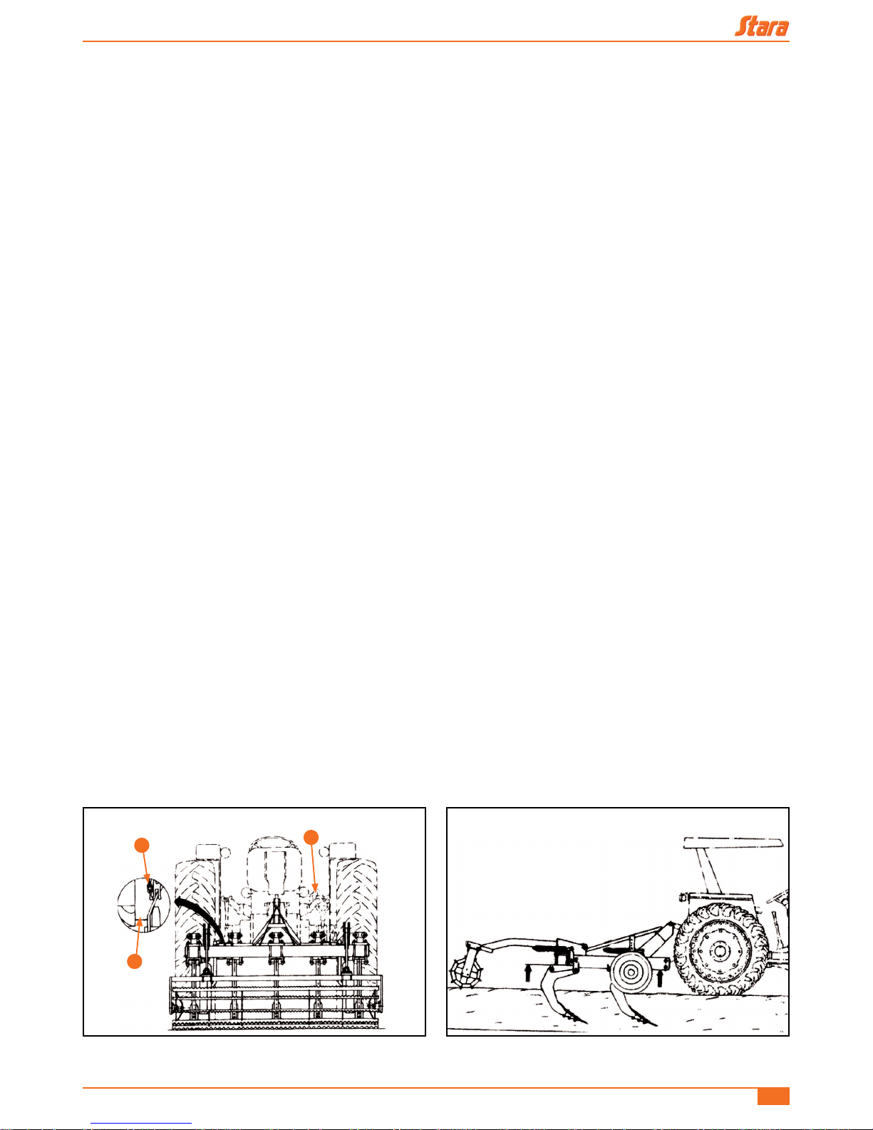
9 - SUB-SOIL PLOW ADJUSTMENTS
9.1 - Shank spacing - Asa CR-DCR/CR/H
The subsoil plow shank (A) can be shifted around, removed or added to the
chassis. The dening factor for spacing and number of shanks all depend on
the subsoil plow model, job depth and soil moisture. This adjustment is done by
loosening the nuts (B) of the screws (C) (Figure 22).
NOTE!
All subsoil plow models leave the factory assembled to a
standard, which is 380 mm between shanks.
9.2 - Shank chassis mounting diagram - Asa CR-DCR/CR/H/KS
9.3 - Job depth - ASA H
The job depth is adjusted by the support wheels. The adjustment is done by the holes on wheel supports, through the
bolts (A) (Figure 25). The two wheels should have the same adjustments, which should maintain a constant job depth,
thus relieving the strain on the tractor’s hydraulics.
Figure 24
Figure 22
A
C
B
Figure 23
760
760
380
380
380
380
760
760 760
Asa H/CR-DCR/CR/KS Instruction Manual and Parts Catalog
18
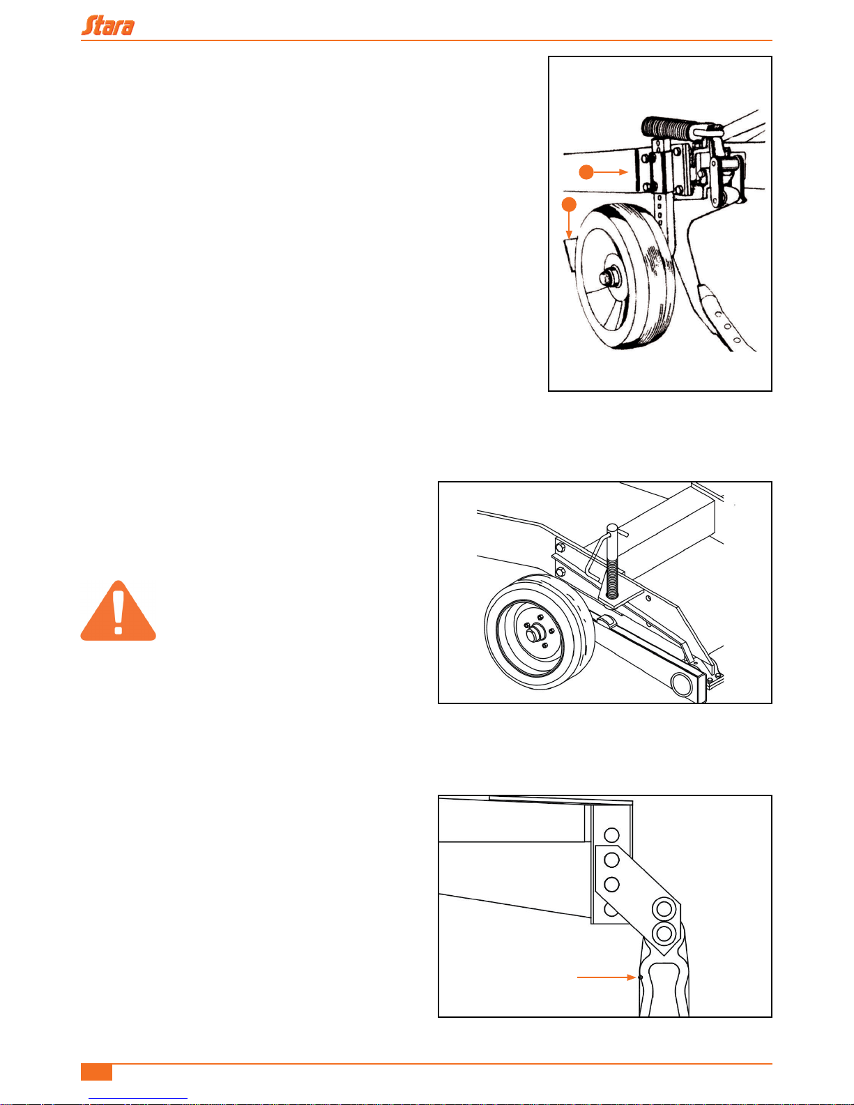
9.3.1 - Wheel cleaner adjustments - Asa H
The cleaning plates (B) (Figure 25) should be adjusted so as to maintain the
wheels clean during the job.
9.4 - Job depth - Asa CR-DCR/CR
The job depth is set by the adjustment rods (Figure 26).
ATTENTION!
The two adjustment rods need to be
adjusted so that they have the same
lengths, thus avoiding tensions on the
wheel axle.
9.5 - Leveling - CR-DCR/CR
So that all the shanks on the Asa Laser penetrate the soil to
the same depth, place the hitch of the header on the holes
that have the best adjustments for the tractor traction bar.
The chassis should remain in a horizontal position with the
subsoil plow planted in the ground. (Figure 27).
Figure 26
Figure 27
Figure 25
A
B
Asa H/CR-DCR/CR/KS Instruction Manual and Parts Catalog
19
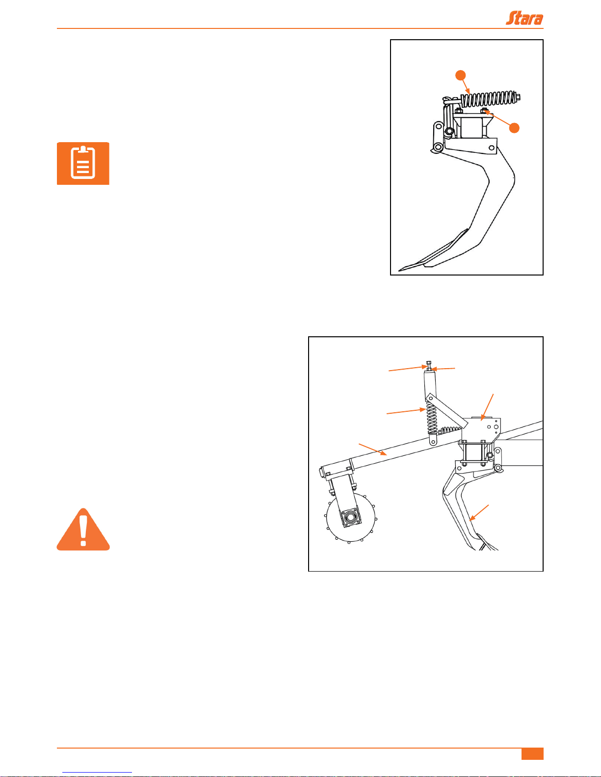
9.6 - Shank quick-release mechanism adjustment - ASA H, CR-DCR/KS/
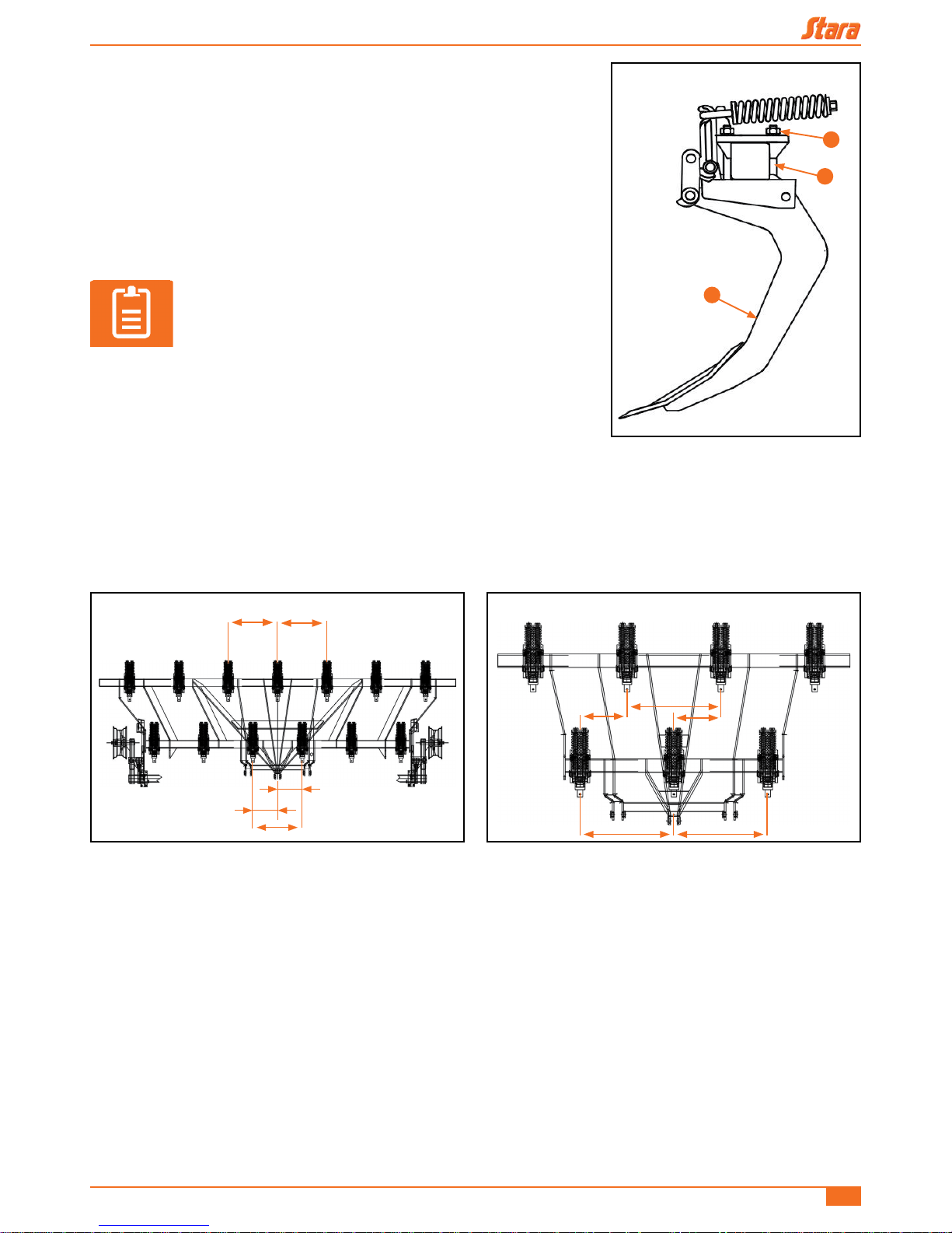
CR
The subsoil plows leave the factory with the adjustment spring length set to 29
cm (A), when under normal working conditions. To increase the spring tension
tighten the spring nut (B), and to lessen the tension, loosen the nut. The spring
length adjustment limits are from 27.5 cm to 30 cm (Figure 28).
NOTE!
For best use of the subsoil plow oscillation, use the lowest
possible tension, as long as the shank is not constantly
disarmed while under normal working conditions.
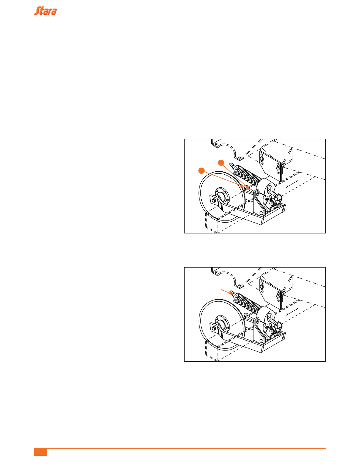
10 - LEVELING ROLLER OPERATION AND ADJUSTMENTS- CR-DCR/H
The leveling roller is an optional component which can be
used on all Stara subsoil plows which support Asa CR and
the Asa CR-DCR. Its function is to till the soil below the
surface, attening dirt mounds in pastures or straw and dirt
clods in the case of direct planting.
The roller pressure can be adjusted according to soil
conditions and the type of ground nish desired. This
adjustment is done using the adjustment screws (Figure
29).
ATTENTION!
The screws need to be adjusted in such
a way that the pressure is constant
throughout the whole leveling roller
length. Also, the pressure adjustment
should be so that the implement will not
be lifted in the air, for that would change
the uniformity of the subsoil.
Figure 28
Max. tightness 27.5 cm
Min. tightness 30 cm
B
A
Figure 29
LOCK NUT
SUPPORT
SHANK
SPRING
ARM
Pressure adjustment
screw
Asa H/CR-DCR/CR/KS Instruction Manual and Parts Catalog
20
Overtightening the tension adjustment screw could damage the support arm.
To adjust the roller tension, follow these steps:
• Adjust for the job depth;
• Loosen the tension adjustment screws and the lock-nut;
• With the subsoil plow planted into the soil, tighten the tension adjustment screws until they begin to t snugly on the
springs;
• Give a couple of more turns on each adjustment screw for a snugger t on the springs.
11 - BLADE DISC GANG ADJUSTMENTS- CR/CR-DCR
The discs need to be adjusted from side to side so that they
remain aligned with the matching shank on the Asa Laser,
and also the depth according to resistance presented by
the hay and stubble, and also the resistance of the soil on
the discs.
11.1 - Lateral tension adjustment of discs- CR/CR-DCR
For the lateral adjustment of the discs, loosen the nuts (A)
of the secured screws (B) and slide the discs until it aligns
with the respective shank, next retighten them again.
Figure 30
A
B
Figure 31
DISC TENSION
ADJUSTMENT NUT
Asa H/CR-DCR/CR/KS Instruction Manual and Parts Catalog
21
11.2 - Blade disc depth adjustments
Factors like undergrowth depth, hay/stubble quantity and moisture, require that blade discs have depth and tension
adjustments.
Disc height adjustment, with relationship to the soil, is done by raising or lowering the tool holder to one of the three
positions available.
The disc tension adjustment with relationship to the soil is done is done by the tension spring nuts and back-nuts of the
disc gang (Figure 31).
11.3 - Hitching the subsoil-plow to the tractor- Asa H
To hitch-up the Asa H Laser use the three point lift system. Consult your tractor’s instruction manual to secure the third
point arm to the tripod. This position will vary according to soil conditions.
11.4 - Centering and leveling the Asa H
The hitching-up of the Asa H Laser is done by a three point lifting system. Consult your tractor’s instruction manual to
secure the third point arm to the tripod. This position will vary according to soil conditions.
• To center and level-out the Asa H Laser to the tractor proceed in this manner:
• Align the subsoil plow tower with the third-point using the stabilizing chains (A) (Figure 32).
• Adjust the hydraulic arms to have the same distance from its relative tire (B) (Figure 32).
• To level the cross-bar of the Asa H, use the leveler on the hydraulic right arm of the tractor (C) (Figure 32). Both arms
should have the same height;
• Adjust the front and rear arms to have the same soil depth, with the subsoil plow planted on the soil check and see
the sides, verify the depths with the job depth selected and the chassis leveling in relationship to the terrain, in that it
should remain leveled to it. Adjust the third point of the tractor (Figure 33).
Figure 33 Figure 32
C
A
B
Asa H/CR-DCR/CR/KS Instruction Manual and Parts Catalog
22
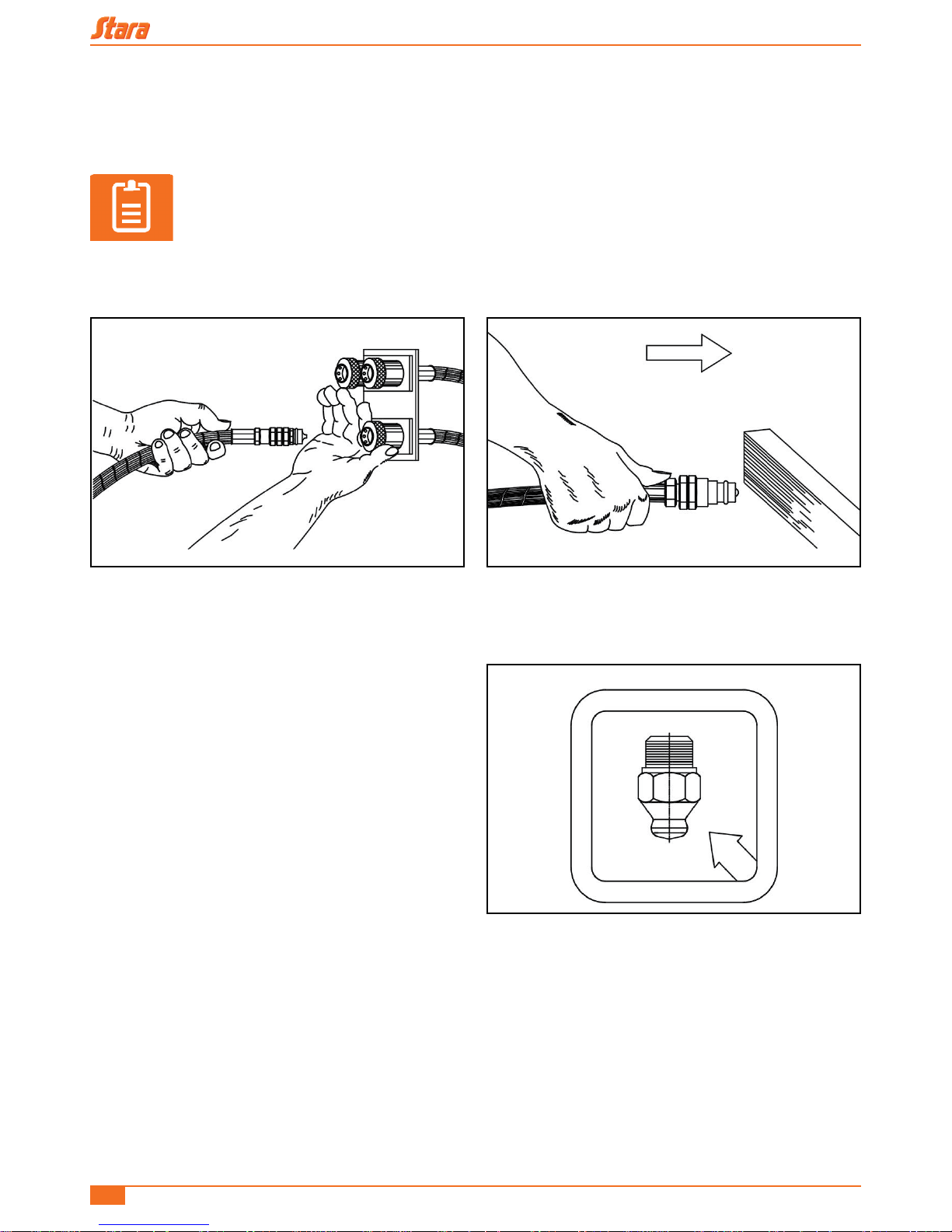
11.5 - Hitching-up the subsoil plow to the tractor- ASA CR-DCR/CR
To hitch-up the implement to the tractor, hook-up the header to the draw-bar and connect the hydraulic lift cylinder hoses
to the quick-disconnects on the tractor remote control.
NOTE!
When hooking-up the hydraulic hoses, make sure that the male ttings are clean by using a clean
cloth, next swipe the inside of the mating female tting with the cloth. To mate the hoses use one
hand force back the actuator on the female connection, and with the other insert the male hose
connection and release the quick-disconnect actuator (Figure 34). Should there be a problem,
push the male needle valve against a at clean surface to relieve the pressure on the needle valve
(Figure 35).
12 - MAINTENANCE
The automatic subsoil plow laser is a heavy-duty and robust
implement. So that its durability is maintained, certain basic
maintenance cares are needed, like:
• a - Daily re-tighten all hardware, since these take-on a
lot of stresses during the job (read reminders which are
posted on the implement as labels, cautioning you);
• b - Daily check for wear of the points. If these show
excessive wear, reverse them or change them out;
• c - Periodically grease the wheel hubs and the bearing
xtures on the leveling roller and the blade discs. Use
grease nº 2. The grease ttings are identied by decals
on the implement;
• d - Periodically check tire pressures. The normal tire pressure is at 40 PSI;
• e - Check for oil leaks on the hydraulic systems. Keep cap covers on all quick-disconnect connections, when not in
use.
• f - If the ASA will not be used for a long period of time, wash it, touch-up the paint job when needed, bathe metal parts
with oil to avoid corrosion and park in a well guarded place.
Figure 34 Figure 35
Figure 36
Asa H/CR-DCR/CR/KS Instruction Manual and Parts Catalog
23
13 - OPERATION
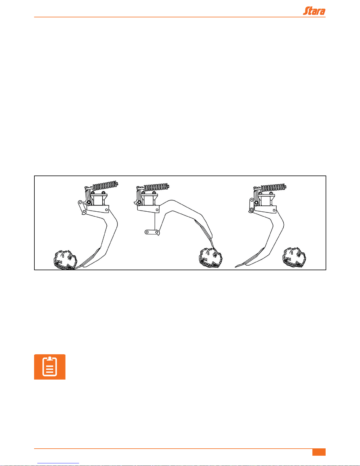
13.1 - Automatic break-away shank system
Stara S/A created and perfected the most modern break-away shank system for subsoil plows, aiming to provide the
operator with greater exibility and efciency when tilling with the sub-soil plow. This system avoids the frequent shearing
of safety pins. When an obstacle is encountered, the shank breaks-away automatically through an arrangement of
springs, and with a simple reversal of the tractor the shanks reset themselves, thus greatly increasing daily actual work
time (Figure 37).
The set of springs on the automatic system act as a shock-absorber against inconsistent resistances encountered by the
subsoil plows, thus providing for a type of subsoil oscillator, minimizing soil tillage and the occurrence of dirt clods on the
surface.
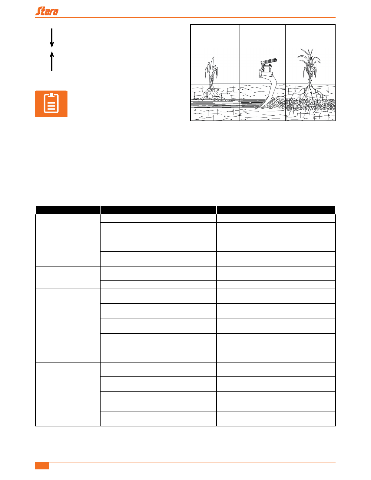
14 - HOW TO TILLAGE
One of the main functions of the Asa Laser is to, break-up compacted layers which form in the soil, normally between 12
and 25 cm deep, and is normally due to machinery tracks and/or animals, or some other forms of soil preparation, and
to promote greater aeration and water inltration, granting better development of the root system of plants and reducing
erosion damage caused by the rain run-off (Figure 37).
To increase soil tillage, simply till to a depth of 2 to 3 cm beyond the compacted layer.
Should you have questions, seek technical assistance to better organize the work and thus avoid costly wastes.
NOTE!
To measure the compacted layer use a penetrometer.
Figure 37
Asa H/CR-DCR/CR/KS Instruction Manual and Parts Catalog
24
WATER (CAPILLARITY)
WATER (INFILTRATION)
NOTE!
For a good tillage job, the soil conditions
need to be favorable with a certain
amount of moisture.
In soil that is extremely dry, with deep and high compactions, we recommend suspending subsoil services in these cases,
since there is greater tractor power demands, and also the whole tiller structure will suffer stresses which could damage
it, or even cause separation.
15 - TROUBLESHOOTING
PROBLEM CAUSE SOLUTION
Tiller not penetrating the
soil, only partially and not
totally.
Tips worn on one or both sides. Flip tips or replace it.
Depth adjustment screw with limited course of
travel.
Turn the two screws CCW until reaching the
desired depth penetration. Adjust both screws to
the same settings.
Job position out-of-line on the horizontal.
Level adjustment is done by changing the hitch
height along with the traction bar.
Automatic break-away
shank system not
working.
Springs over-tightened.
Adjust the spring tension as listed on the labels.
Maximum: 27.5 cm.
Shank rollers seizing. Lubricate with oil or replace it.
Automatic break-away
shank too repetitive.
Poor spring tension.
Adjust the spring tension as listed on the labels.
Maximum: 27.5 cm.
Lever with excessive wear on the roller
engagement.
Replace the lever.
Soil with a high index of compaction.
Reduce job speed and/or replace the n° 3 tips for
n° 2 tips.
Areas with a high incident of obstacles, such as
rocks, stumps, roots, etc.
Reduce job speed and/or avoid these areas.
Tractor power and job speed above
recommended.
Work within power specications and the
manufacturer’s recommended speeds.
Main chassis fractured or
twisted.
Springs overtightened.
Adjust the spring tension as listed on the labels.
Maximum: 27.5 cm.
Screw quality below required standards.
Replace them for the original required 8.8 quality
parts (Steel screw).
Making tight curves or nishing touches with the
tiller planted in the soil.
In order to do these maneuvers, remove the
implement’s arms off the ground by using the
remote control.
Break-away shank system not disarming.
Adjust the spring tension as listed on the labels.
Maximum: 27.5 cm.
Figure 38
Table 3
Asa H/CR-DCR/CR/KS Instruction Manual and Parts Catalog
25
16 - TROUBLESHOOTING (CONTINUED)
PROBLEM CAUSE SOLUTION
Quick-disconnects do not mate.
Connections with different tting
types.
Change-out all ttings for the proper
matching and mating parts.
Implement does not move in any
direction or moves with difculty.
Plug pressures different. Adjust or replace, as needed.
Hydraulic tubing obstructed or
crushed.
Clear the line or replace the tubing.
Poor controller hydraulic pressure.
Adjust the controller using the relief valve,
with the help of a manometer. Normal
pressure is 180 kg/cm².
Hoses swapped.
Verify the hoses in detail and reinstall
correctly.
Hydraulic cylinders with defects.
Replace the repairs or replace the
cylinders.
Tractor’s hydraulic system
undersized.
Conrm by replacing it and/or repair it.
Oil level too low. Fill to the proper level.
Hoses with crimped ttings leak.
Poorly tightened. Retighten with caution.
Lacking thread sealant.
Use sealing tape and retighten with
caution.
Hoses with swivel ttings/SAE
JIC-37º, are leaking.
Poorly tightened. Retighten with caution.
Flared tubing face damaged.
Cut-off a piece of the damaged tubing and
re-are the tubing.
Hydraulic cylinders leak.
Repairs damaged. Replace the repairs.
Shank damaged Replace shank.
Oil with impurities.
Change the oil, replace the repairs and
lter element.
Job pressure above recommended.
Adjust the controller using the relief valve,
with the help of a manometer. Normal
pressure is 180 kg/cm².
The implement moves without
applying the controller.
Poorly tightened. Retighten with caution.
Lacking thread sealant.
Use sealing tape and retighten with
caution.
Repairs damaged. Replace the repairs.
Hydraulic cylinders with repairs
damaged.
Identify the cylinder and replace the
repairs.
Table 4
Asa H/CR-DCR/CR/KS Instruction Manual and Parts Catalog
26
17 - ASA LASER KS SEEDING KIT
The Asa Laser KS Seeding Kit is mounted on top of the Asa CR-DCR tiller chassis, on versions with 5, 7, 9, 11 and 13
shanks. You can purchase the complete assembly, tiller + seeding kit package as one, or just the KS Seeding Kit if you
already have a CR-DCR Laser subsoil tiller.
The transmission is driven by the levelling roller on the tiller, not needing a ratcheting mechanism to drive it.
Using the Asa Laser KS allows the seeder to cast seeds like millet or oats as a winter covering after the summer harvest
in areas of direct planting or conventional. Also it can seed other commodities like wheat, barley, white oats, etc. with an
approximate surface covering of 95% of the seeds.
The terrain levelling and seed propagation is done with the levelling roller.
One of the major benets of the Asa Laser KS come along the lines of how it is economical, this is due to the reduction of
operations required, since it tills, seeds, spreads seeds and levels the terrain in one pass, all in an agronomic sequence,
in order to avoid that the soil is re-compacted again, thus making the whole operation in one pass thus facilitating
and quickly expanding the root systems, enhancing the soil structure and taking advantage of the nutrients within the
commodity.
The Asa Laser KS used properly can have a long useful life, turning your investment highly protable. Thus, we
recommend that you carefully read your instruction manual and always consult it when there are questions.
18 - ASA LASER KS MAIN COMPONENTS
The Asa Laser KS seeding Kit is mounted on the ASA-CR-DCR subsoil tiller, which consists of the following components:
1 - Hitch 6 - Transmission system
2 - Blade discs 7 - Seed reservoir
3 - Chassis 8 - Catwalk
4 - Subsoil shanks 9 - Hand-rail
5 - Levelling rollers
Figure 39
9
8
6
5
4
2
7
3
1
Asa H/CR-DCR/CR/KS Instruction Manual and Parts Catalog
27
19 - TECHNICAL SPECIFICATIONS - ASA LASER KS
ASA LASER KS
Number of lines 5 lines 7 lines 9 lines 11 lines 13 lines
Job width (m) 1.90 m 2.66 m 3.42 m 4.18 m 4.94 m
Hp required (hp) 75 to 105 105 to 130 135 to 160 165 to 250 195 to 250
Box capacity (liters) 225 315 405 495 585
Job speed (km/h) 4 to 7 km/h
Weight (kit + sub-soil plow) (kg) 1.535 1.895 2.305 3.000 3.385
Implement width (m) 2.14 2.96 3.76 4.78 5.58
Number of rolls 1-2 m 2 - 1.4 m 2 - 1.8 m 2 - 1.4 m + 1 - 1.8 m 3 - 1.8 m
Length 4.75 m
Total height 1.85 m
Job depth 20 to 35 cm
Reservoiros and lids Manufactured of polyethylene
20 - MAINTENANCE - ASA LASER KS
The tiller maintenance instructions are found in the Asa CR-DCR “Laser” tiller manual. Carefully read it before using it.
So that all the implement resources are taken advantage of in its durability and precision, some special cares need to
be implemented:
With daily use, also inspect all hardware, nuts and bolts (brackets, bearings, etc.) and retighten as needed.
• When in use, daily check all hardware, brackets, bearing xtures, and retighten as needed.
• Daily grease all grease ttings where there is some type of grinding or rubbing in-between parts. Grease ttings are
identied by decals on the implement..
NOTE!
Do not remove excess grease which forms in time with lubrications, since it serves as excellent
barrier against water and other contaminants.
• After using the implement use high spray jets to wash-down the equipment (do not use chemical products, since they
can damage the paint nish) in order to remove all residual products , and soak and bathe all metallic parts to avoid
rusting.
• When necessary touch-up the paint nish to avoid the rusting of the implement.
ATTENTION!
Before relling the implement verify that the transmission system is spinning freely (to do so spin
the levelling roller forward 3-4 turns). Should it not be so, check the whole system, clearing any
obstacles and thus avoiding damages to the transmission.
Table 5

Asa H/CR-DCR/CR/KS Instruction Manual and Parts Catalog
28
21 - ASSEMBLY OF THE ASA LASER KS
The seeding Kit (KS) is mounted on the ASA-CR-DCR “LASER” tiller chassis and the transmission is driven by the
levelling roller on the right side of the tiller.
The chassis / platform / kit seeding reservoir (KS) package leave the factory pre-assembled, the only thing remaining is
the installation of these items onto the tiller chassis and the alignment of the second chain which ties the transmission to
the levelling roller.
21.1 - Levelling roller transmission installation
Normally the transmission part which stays tied to the roller leaves the factory already installed, but if the seeding kit is
purchased to be installed onto the ASA-CR-DCR LASER tiller already in your possession, it is required that you mount
on the roller chassis the outer body cover support, upper axle, the “A” and “B” gears, the rst chain and protective outer
body cover. To do so follow the assembly diagram as shown on gure below.
IMPORTANT!
When mounting the rst chain, note its
alignment in relationship to the support,
according to dimensions shown on
(Figure 41). If needed, adjust the axle
positions, being careful to tighten
the cam ring as shown on View “X” of
(Figure 40).
Figure 41
Spacer bushing
Spacer bushing
20 width
30
30
25.5 width
Figure 40
Travel direction
(X)View
“x”
 Loading...