

Page 1

LINE THERMAL PRINTER
W inT pe 800C
TECHNICAL MANUAL
y
Page 2

NOTICE
• All rights reserved. Reproduction of any part of this manual in any
form whatsoever, without STAR’s express permission is forbidden.
• The contents of this manual are subject to change without notice.
• All efforts have been made to ensure the accuracy of the contents
of this manual at the time of going to press. However, should any
errors be detected, STAR would greatly appreciate being informed of them.
• The above notwithstanding, STAR can assume no responsibility
for any errors in this manual.
© Copyright 1996 Star Micronics Co.,Ltd.
Page 3

INTRODUCTION
This manual describes the WinType 800C line thermal printer.
It is intended for use as a reference for periodic inspections and maintenance procedures.
This manual is prepared for use at a technical level and not for the general user.
• This manual is divided into the following sections:
Chapter 1 General Specifications
Chapter 2 Adjustments
Chapter 3 Parts Replacement
Chapter 4 Maintenance and Lubrication
Chapter 5 Troubleshooting
Chapter 6 Parts List
1
2
3
4
5
6
7
Page 4

– 1 –
GENERAL SPECIFICATIONS
CHAPTER 1
GENERAL SPECIFICATIONS
1. General Specifications..........................................................................................3
2. External Dimensions.............................................................................................4
3. Control Panel .........................................................................................................6
4. Interface .................................................................................................................7
4-1. Connector Signals .................................................................................................. 7
5. DIP-SW Settings (Tentative) .................................................................................8
1
Page 5

– 3 –
GENERAL SPECIFICATIONS
1. General Specifications
Engine
Printing process Thermal wax transfer
Resolution 300 X 300 dpi
Printing speed
Letter size paper Monochrome 31 seconds/page
3 color (YMC) 64 seconds/page
4 color (YMCB) 80 seconds/page
A4 size paper Monochrome 32 seconds/page
3 color (YMC) 67 seconds/page
4 color (YMCB) 85 seconds/page
Legal size paper Monochrome 37 seconds/page
3 color (YMC) 87 seconds/page
4 color (YMCB) 107 seconds/page
Special A4 size paper Monochrome 37 seconds/page
3 color (YMC) 87 seconds/page
4 color (YMCB) 107 seconds/page
Paper feed
Speed Paper: 4, 6, 8 or 10 ms/line (depending on data transfer speed)
OHP film: 6, 8 or 10 ms/line (depending on data transfer speed)
Paper handling Paper tray Capacity: 50 sheets of coated/presentation grade paper
Paper stacker: 10 sheets
Manual insertion:Available
Interface Centronics parallel
Power supply 120VAC, 220VAC, 230VAC, 240VAC, 50/60Hz
(varies according to the country of purchase)
Power consumption At standby: 17W
At printing: 120W
Dimensions 14.13" (W) x 10.08" (D) x 5.04" (H)
(359mm (W) x 256mm (D) x 128mm (H))
Weight 16.5 lbs. (7.5 kg.)
Reliability information Printer life 25,000 pages or 5 years
Printer head life 5,000 pages (A4 size, 3 color, 20% duty)
Noise level ISO-7779
53.0 dB
Environment
Temperature Operating: +10° to +35°C (50° to 95°F)
Non-operating: -20° to +55°C (- 4° to 131°F)
Humidity Operating: 30 to 70% RH (no condensation)
Non-operating: 30 to 90% RH (no condensation)
Page 6
– 4 –
GENERAL SPECIFICATIONS
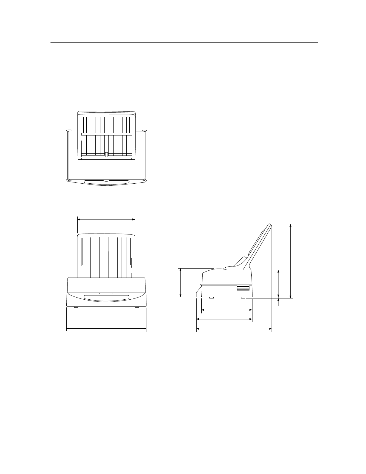
2. External Dimensions
Fig. 1 - 1 External Dimensions
260
359
5
234
122
335
256
341
128
Page 7
– 5 –
GENERAL SPECIFICATIONS
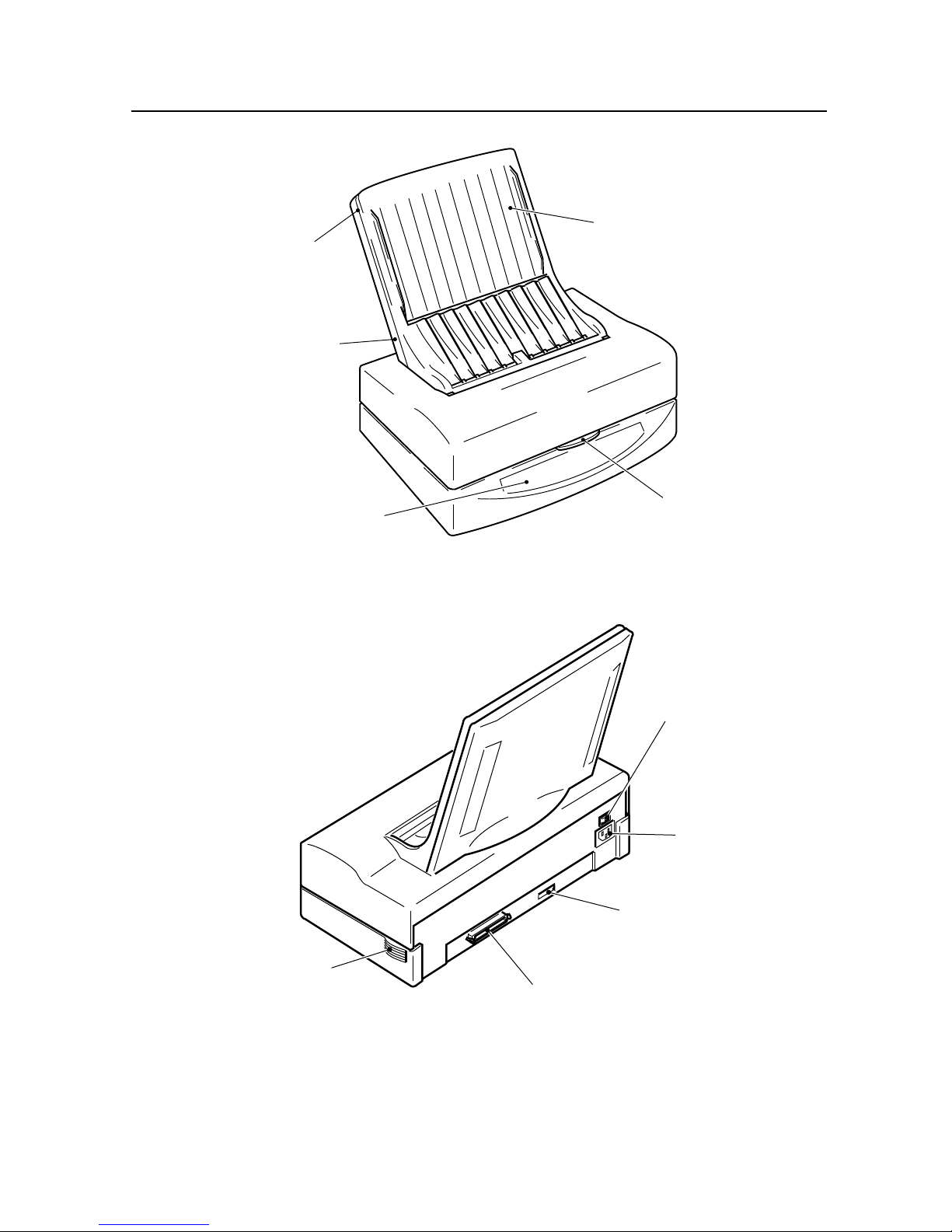
Fig. 1 - 2 Front View of the Printer
Fig. 1 - 3 Rear View of the Printer
Paper Tray
(Abbreviation of Paper
Tray Base and Paper
Tray Cover)
Paper Tray Cover
Paper Tray Base
Control Panel
Top Cover
Release
Power Supply
Switch
Power Supply
Connector
DIP Switches
Parallel Interface
Cooling Fan
Vents
Page 8
– 6 –
GENERAL SPECIFICATIONS
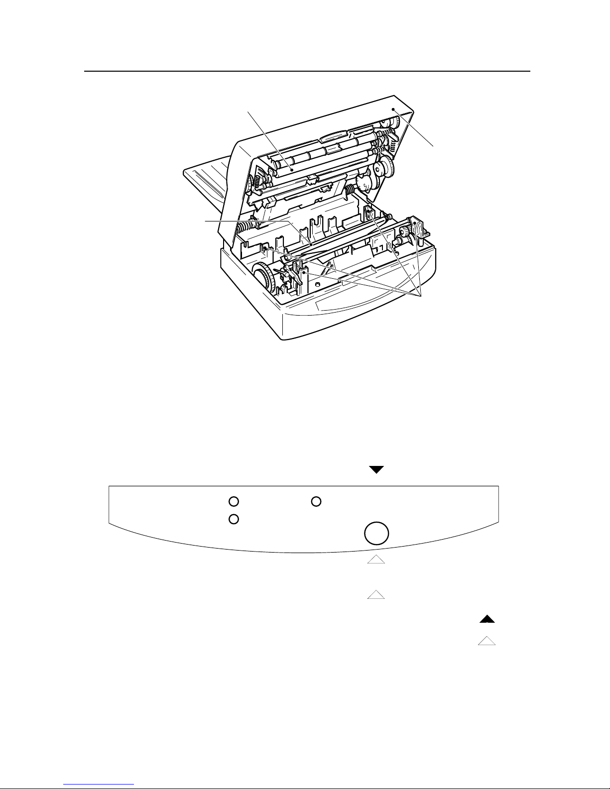
Paper
Film Roll
Ready
3. Control Panel
Fig. 1 - 4 View of the Inside of the Printer
Platen Roller
Top Cover
Thermal Head
Bobbin Sockets
Power ON
ONLINE/READY
OFFLINE/NOT READY
OFFLINE (Not Ready)
ONLINE (READY)
Test Print
Hold
Push
Fig. 1-5 Control Panel
Page 9
– 7 –
GENERAL SPECIFICATIONS
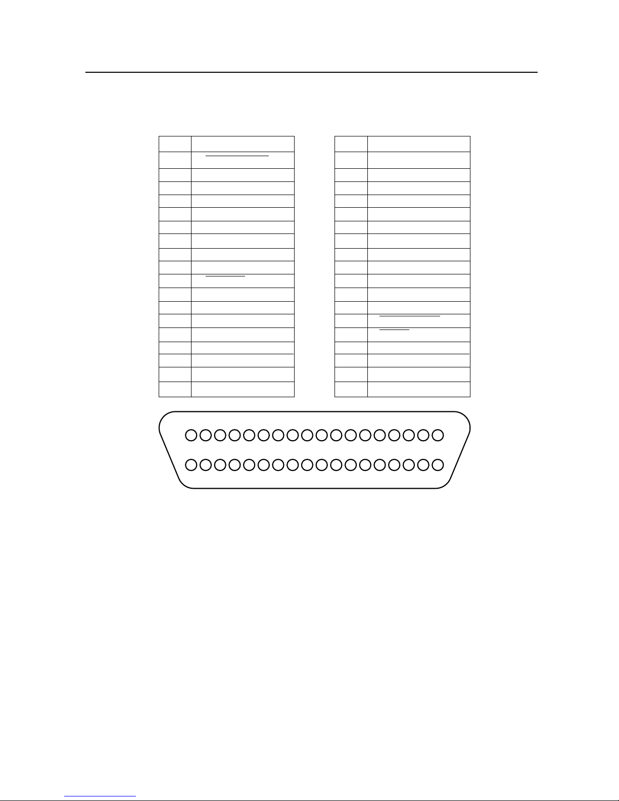
4. Interface
4-1. Connector Signals
Pin Signal Pin Signal
1 DATA STROBE 19 GND
2 DATA 1 20 GND
3 DATA 2 21 GND
4 DATA 3 22 GND
5 DATA 4 23 GND
6 DATA 5 24 GND
7 DATA 6 25 GND
8 DATA 7 26 GND
9 DATA 8 27 GND
10 ACKNLG 28 GND
11 BUSY 29 GND
12 EOP 30 GND
13 ON LINE 31 INPUT PRIME
14 GND 32 FAULT
15 33 GND
16 GND 34 EOI
17 CHASSIS GND 35
18 +5V (Max. 160mA) 36
118
19
36
Fig. 1-6 Pin Assignment
Page 10

– 8 –
GENERAL SPECIFICATIONS
5. DIP-SW SETTINGS (Tentative)
SW No. Function
1, 2 MEDIA mode
SW1 SW2
ON ON Coated paper mode
(A-PWC, A4-PWC, SA-PWC, SA4-PWC)
ON OFF Normal paper mode (Hammermill 10468-7, Xerox L-A4)
OFF ON OHP film mode (A-TFC, A4-TFC, SA-TFC, SA4-TFC)
OFF OFF Not Used (Coated paper mode)
3, 4, 5 Film roll type
SW3 SW4 SW5
ON ON ON TL1-11C3H 3 color film roll for Letter and A4
ON ON OFF TL1-14C3H 3 color film roll for Legal and SA4*
ON OFF ON TL1-11C4H 4 color film roll for Letter and A4
ON OFF OFF TL1-14C4H 4 color film roll for Legal and SA4*
OFF ON ON TL1-CBH monochrome film roll
OFF ON OFF Not used (monochrome film roll)
OFF OFF ON Not used (monochrome film roll)
OFF OFF OFF Not used (monochrome film roll)
6 Print Media Size
SW6
ON Letter or A4
OFF Legal or Special A4
7, 8, 9 Density
SW7 SW8 SW9 Density
ON ON ON 0 (Default)
ON ON OFF +1
ON OFF ON +2
ON OFF OFF +3 (Darkest)
OFF ON ON –1
OFF ON OFF –2
OFF OFF ON –3 (Lightest)
OFF OFF OFF Not used (Default)
10 Reserved
SW10
ON Normal
OFF TEST 2 (Factory test mode)
Notes:
Factory setting: 1234567890
OFF
ON **********
*SA4 means 'Special A4' which size is 210 X 335.6 mm.
Page 11

– 9 –
CHECK AND ADJUSTMENT
CHAPTER 2
ADJUSTMENTS
1. Adjusting power output voltage ........................................................................11
1-1. Adjusting thermal head voltage .......................................................................... 11
1-2. Checking that there is 5V......................................................................................11
2. Circuit Diagram....................................................................................................12
3. Off-register...........................................................................................................13
3-1. Preparations.......................................................................................................... 13
3-2. Checking off-register............................................................................................ 13
3-3. X direction only..................................................................................................... 14
3-4. X and Y directions ................................................................................................ 14
2
Page 12

– 11 –
CHECK AND ADJUSTMENT
1. Adjusting power output voltage
1-1. Adjusting thermal head voltage
(1) Turn OFF the power to the printer.
(2) Take the Harness Head Power Connector off of the Thermal Head.
(Refer to "1. Thermal Head" in Chapter 3.)
(3) Turn ON the power to the printer.
(4) Measure the voltage of pins 1 – 6 (VTM) and 7 – 12 (GND) of the Harness Head Power Connector. The
left edge pin of the Power Supply is pin 1.
(5) Adjust so that there is 24.5V (±0.1V) in the Thermal Head. (You can adjust by using a regular (+) screw
driver to rotate the VTH adjustment screw.)
(6) After adjusting, turn ON the power to the printer.
(7) Connect the Harness Head Power and attach the Thermal Head.
1-2 Checking that there is 5V
(1) Turn OFF the power to the printer.
(2) Take the Harness Head Power Connector off of the Thermal Head.
(3) Turn ON the power to the printer.
(4) Measure the voltage of pins 13 (5V) and 7 – 12 (GND) of the Harness Head Power Connector.
(You cannot adjust the voltage here.)
5V Vth
Power Supply
Adjust using a (+) screwdriver.
Page 13
– 12 –
CHECK AND ADJUSTMENT
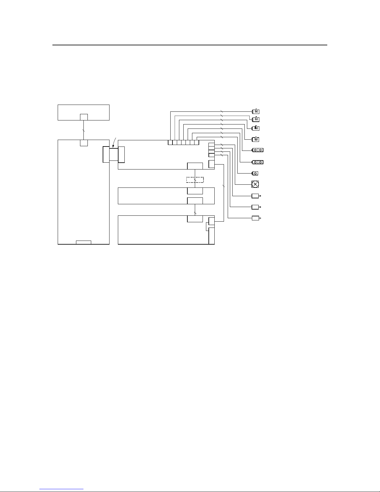
2. Circuit Diagram
Control PCB
Centronics
I/F PC Board
Harness I/F J11
Harness Head J12
Thermal Head
Power Supply
J18 J20 J22 J24
J19 J21 J23
YELLOW
GREEN
RED
VIOLET
PINK
BLUE
BROWN 2
2
2
3
3
3
3
2
6
4
4
9
BLK
Harness Head Power
BLK
13
9
13
13
16
J14 2
J17 6
J16 5
J15 4
Engine PCB
Ferrite Core
Harness Engine J30
3030 30
J11
Film Roll DOWN Sensor (includ.
Base)
Film Roll UP Sensor
(includ. Roller Base Unit)
Paper Start Sensor
(includ. Roller Base Unit)
Head Fan (includ. Base)
Paper Motor
Film Roll Motor
Head U/D Motor
FAN
J12
J30
9
Cam Sensor (includ. Roller Base Unit)
EOP Sensor (includ. Paper Plate Unit)
Cover Open Sensor (includ. Paper Motor)
Paper Edge Sensor
(includ. Roller Base Unit)
Page 14
– 13 –
CHECK AND ADJUSTMENT
3. Colour off-register
This printer is shipped from the factory after it has undergone thorough colour off-register adjustments. However,
colour off-register may occur as a result of any of the following causes.
• Use of the printer over a long period of time.
• Replacement of the Thermal Head Unit, Upper Mechanical Unit or the Lower Mechanical Unit.
If this should occur, adjust using the following procedures.
3-1. Preparations
(1) Set the left side Pinch Roller Spring positions to F2 and B2. (Refer to section 3-4)
(2) Set the right side Pinch Roller Spring positions to F2 and B2. (Refer to section 3-4)
(3) If you have just finished cleaning the Platen Rollers and Pinch Rollers, print more than 10 sheets.
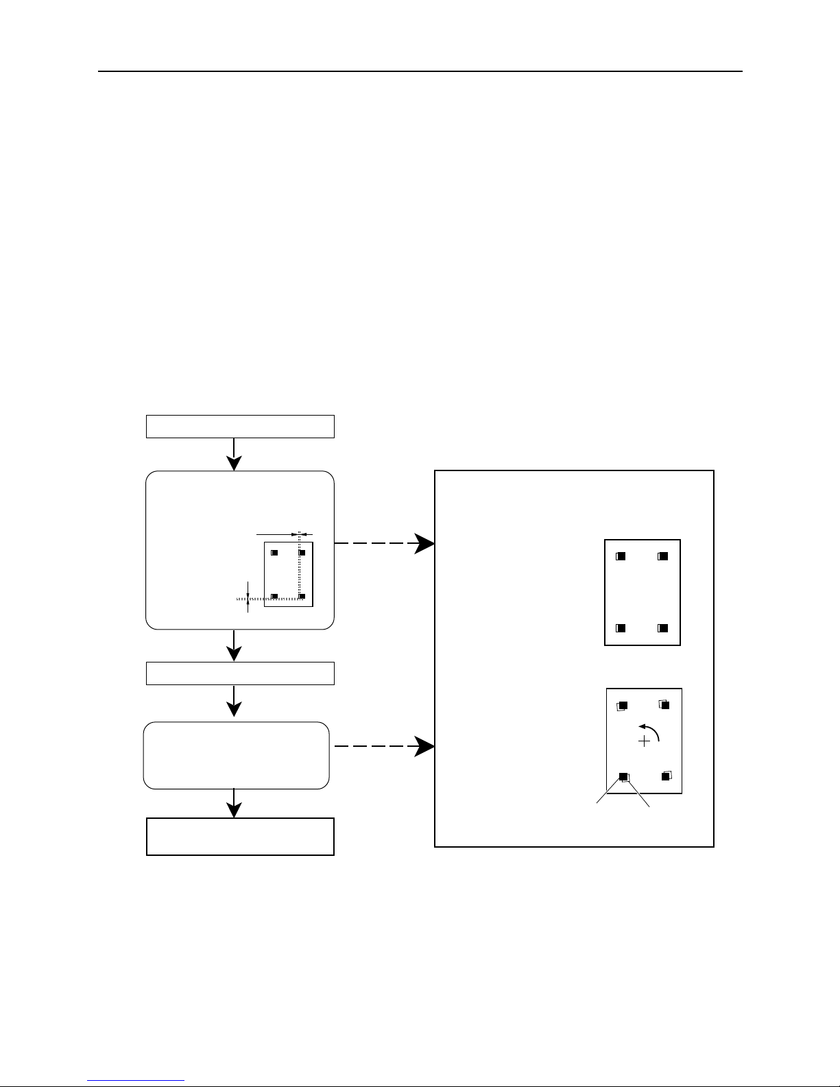
3-2. Checking colour off-register
Print 1 self test.
Print 4 more self tests.
Are points 1 – 4 colour offregister less than 0.25mm in the
X or Y directions for all five
tests?
yes
no
no
Are points 1 – 4 colour offregister less than 0.2mm in the X
orY directions?
Adjustment is needed. Adjust according to the
type of colour off-register.
Magenta Yellow
or Cyan
The colour off-register
occurred to parallelism.
(Refer to section 3-3)
The colour off-register
occurred to turn.
(Refer to section 3-4)
Y Direction
It is within the tolerance range.
Further adjustment is not needed.
yes
X Direction
Page 15

– 14 –
CHECK AND ADJUSTMENT
Standard
112321314233524345545
Left Side Hook Position
Right Side Hook Position
3-3. The colour off-register occurred to parallelism
3-4. The colour off-register occurred to turn
(2) If colour off-register occurs even though item (1) is correct, replace the Roller Base
Unit.
(2) If colour off-register are not correct, refer to the following table and change the left
and right Pinch Roller Springs' hook positions.
(1) Check that the fitting of the Head Spring of the Thermal Head Unit is correct.
(It should be standing vertically .)
Incorrect
After adjusting, refer to the previous page and check that colour off-register is correct.
545543425332413123211
Thermal head
Head bracket
(1) Change the Pinch Roller Springs' hook positions on the left-side of the Roller Base
Unit. (The right-side of the Roller Base Unit position of 3 )
Example of yellow is in the
case of left-turn.
Magenta Yellow
or Cyan
Springs get tighter as
numbers get larger.
(F)
(B)
F2
F1
F3
B1
B2
B3
1
2
3
4
5
• If YELLOW is in
the case of left-turn
, loosen the spring.
• If YELLOW is in
the case of right-turn
, tighten the spring.
YELLOW
right-turn
YELLOW
left-turn
After adjusting, refer to the previous page and check that colour off-registe is correct.
Page 16

– 15 –
PARTS REPLACEMENT
CHAPTER 3
PARTS REPLACEMENT
1. Thermal Head ......................................................................................................17
2. Paper Motor .........................................................................................................19
3. Centronics I/F PC Board.....................................................................................21
4. Engine PC Board.................................................................................................23
5. Control PC Board ................................................................................................24
6. Power Supply (First Half) ...................................................................................25
7. Power Supply (Second Half) ..............................................................................27
8. Film Roll Motor ....................................................................................................28
9. Base......................................................................................................................29
10. Cover Shaft Unit ..................................................................................................30
11. Paper Plate Unit ...................................................................................................31
12. Head U/D Motor ...................................................................................................32
13. Top Cover.............................................................................................................33
14. Torque Limit and Roller Base Unit ....................................................................34
1
2
3
Page 17
– 17 –
PARTS REPLACEMENT
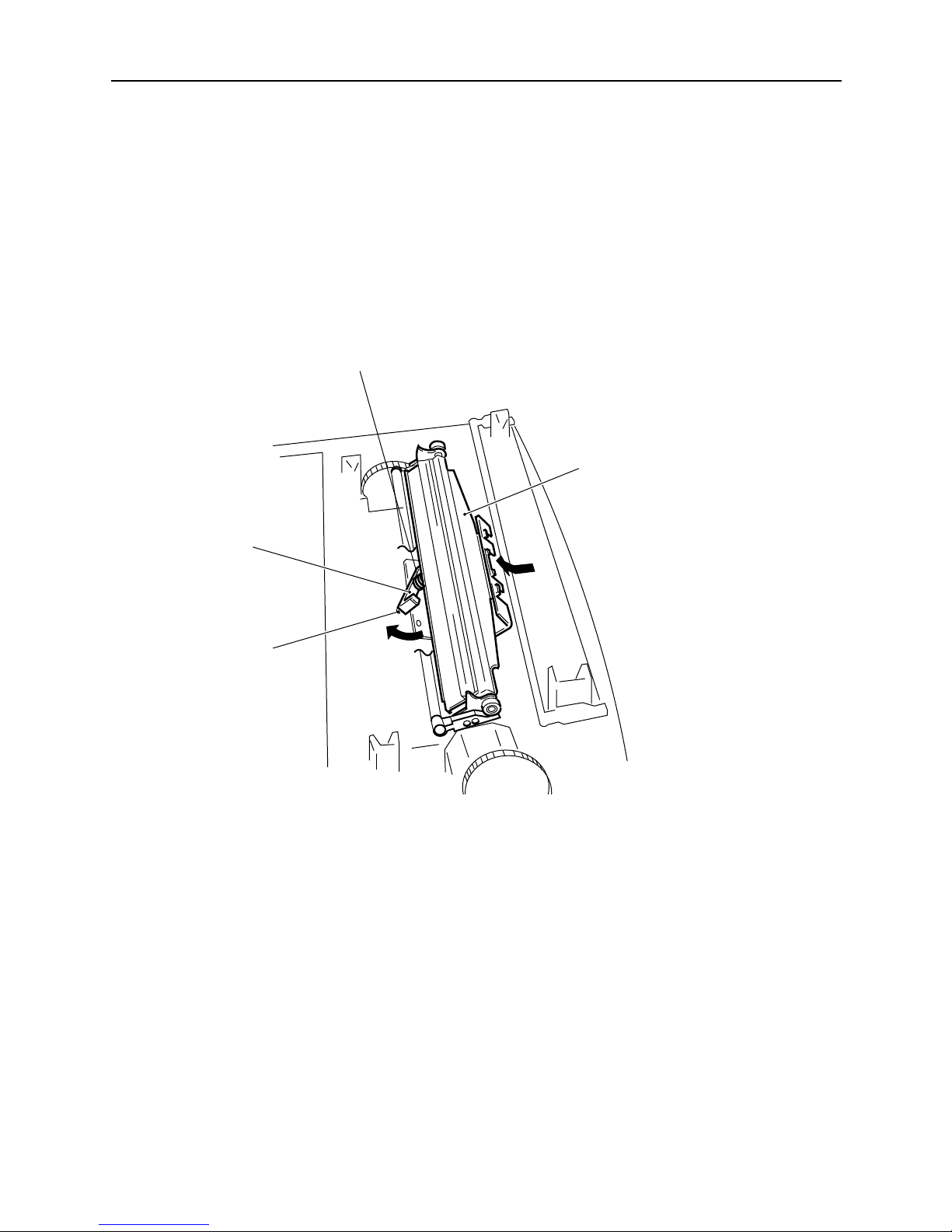
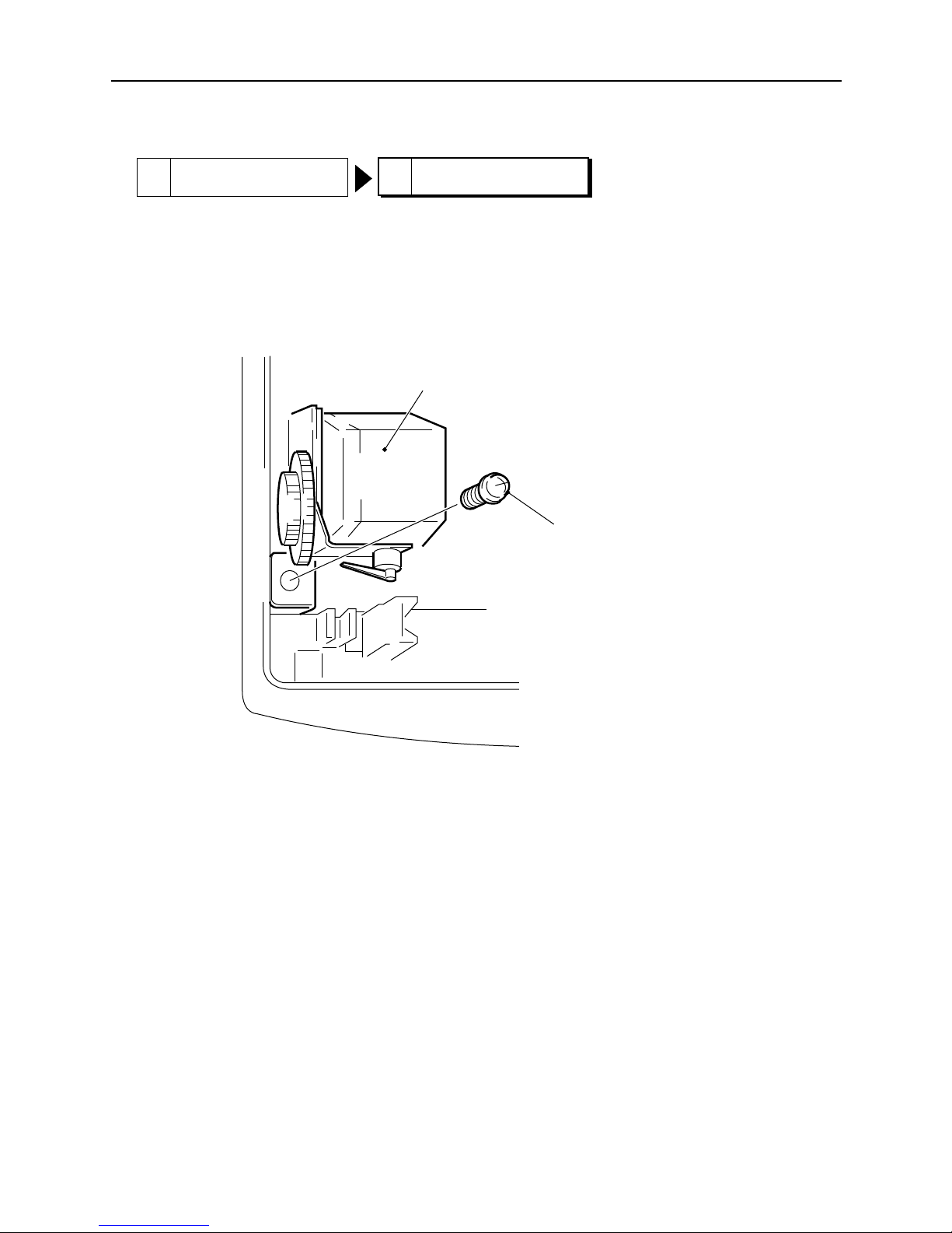
1. Thermal Head
[Remove]
(1) Lift up the left side of the Stopper Head and remove the protruding piece.
Rotate in the direction of arrow (a).
(2) Push the Thermal Head in the direction of arrow (b) and remove the Thermal Head Hook. Be careful
because the pressure of the Spring pushes the Thermal Head upward.
Stopper Head
Protruding
Piece
Thermal Head
Spring Head Pin
(b)
(a)
Page 18
– 18 –
PARTS REPLACEMENT
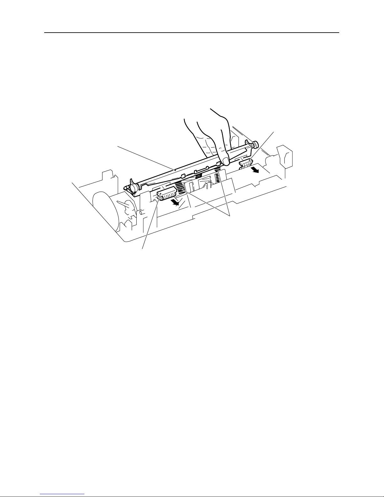
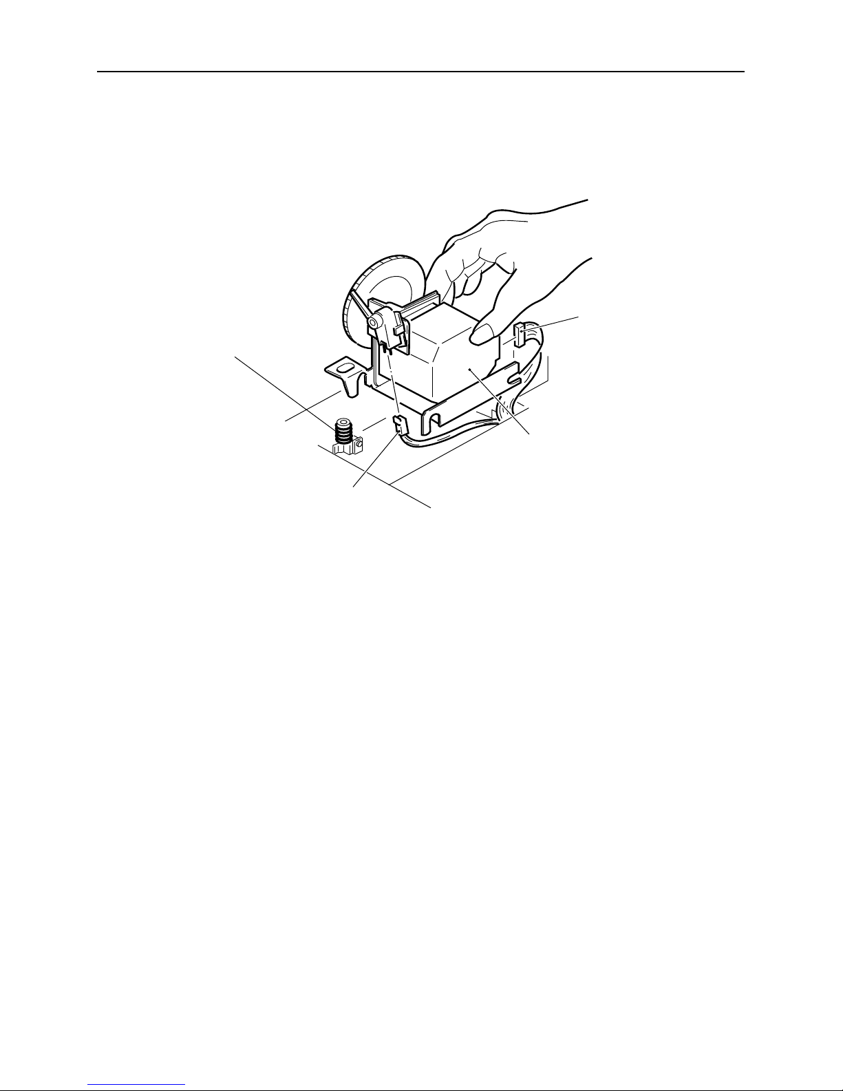
(3) Remove Harness Head J12 and the Harness Head Power Connector.
When doing this, the Spring Heads (2 pcs.) and Spring Head Pins will come loose. Take special care not to
loose them.
[Caution in assembly]
Attachment is done by reversing the procedures used for removal.
Harness Head Power
Spring Head
Thermal Head
Harness Head J12
Page 19
– 19 –
PARTS REPLACEMENT
2. Paper Motor
[Remove]
(1) Remove the Self-tap Screws fastening (M3 X 10) the Paper Motor.
Paper Motor
Self-tap screws
(M3 X 10)
1 Thermal Head
2 Paper Motor
Page 20
– 20 –
PARTS REPLACEMENT
(2) Lift up the Paper Motor and remove the Connector. (Two places in the motor and sensor.)
When doing this, the Spring Paper Motor will come loose. Be careful not to lose it.
[Caution in assembly]
Attachment is done by reversing the procedures used for removal.
Insert the Base Pin into the rear groove of the Paper Motor from the front and insert the Base Pin into the front
groove of the Paper motor coming down from above.
After attaching, check to make sure that springs for the Spring Paper Motor are securely fastened. When pushing
down on the Paper Motor from above, the Paper Motor should move smoothly back to its original position with the
force of the Springs.
Connector
Paper Motor
Spring Paper Motor
Connector
Page 21
– 21 –
PARTS REPLACEMENT
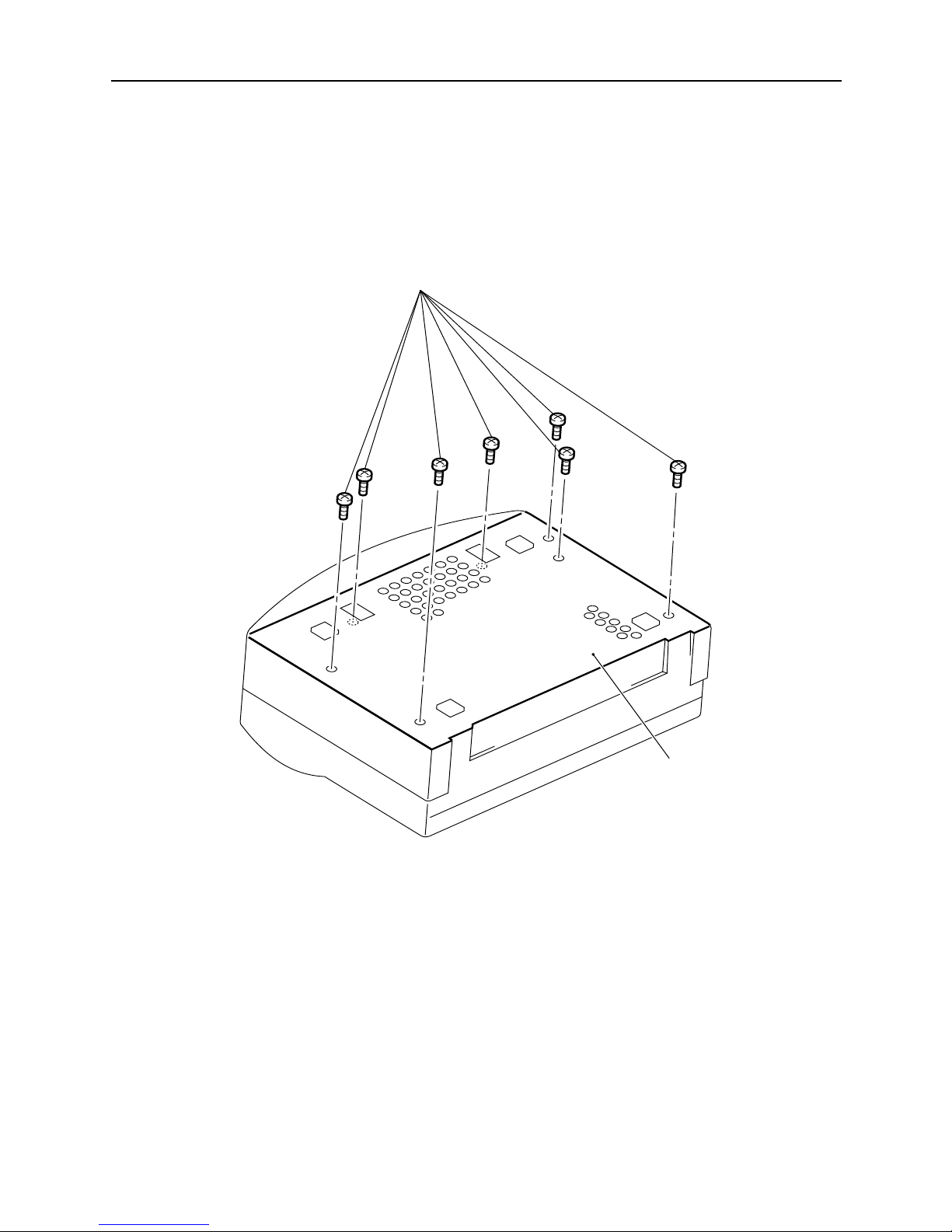
3. Centronics I/F PC Board
[Remove]
(1) Turn the printer upside down.
(2) Remove the Self-tap Screws (7 places/M3 X 10) from the ASSY Plate Bottom.
ASSY Plate Bottom
Self-tap Screws (M3 X 10)
Page 22

– 22 –
PARTS REPLACEMENT
(3) Remove the SW-PW-P Pan Head Screws (5 places/M3 X 10) fastening the I/F Cover.
(4) Remove the Self-tap Screws (4 places/M3 X 10) fastening the Centronics I/F PC Board.
(5) Remove Harness I/F J11 Connector and Control PC Board Harness Connector from the Centronics I/F PC
Board.
Self-tap Screws (M3 X 10)
Control PC Board Harness
Centronics I/F PC Board
SW-PW-P Pan Head Screws
(M3 X 8)
Harness I/F J11
I/F Cover
[Caution in assembly]
Attachment is done by reversing the procedures used for removal.
The Harness Connector for the Control PC Board should be attached so that the blue mark can be seen.
Page 23

– 23 –
PARTS REPLACEMENT
4. Engine PC Board
3 Centronics I/F PC Board
4 Engine PC Board
[Remove]
(1) Remove the Connectors (14 places) from the Engine PC Board.
(2) Remove the Self-tap Screws (2 places/M3 X 10) fastening the Engine PC Board.
Self-tap Screws
(M3 X 10)
Engine PC Board
[Caution in assembly]
Attachment is done by reversing the procedures used for removal.
Page 24

– 24 –
PARTS REPLACEMENT
5. Control PC Board
[Remove]
If you have already removed 3 Centronics I/F PC Board , perform only step (4).
(1) Turn the printer upside down.
(2) Remove the Self-tap Screws (7 places/M3 X 10) fastening the ASSY Plate Bottom.
(3) Remove the Harness Connector of the Control PC Board from the Centronics I/F PC Board.
(4) Remove the Self-tap Screws (2 places/M3 X 10) fastening the Control PC Board.
Self-tap Screws
(M3 X 10)
[Caution in assembly]
Attachment is done by reversing the procedures used for removal.
Tighten the screws while pressing the Control PC Board to the Base so that the gap between the Control PC Board
and the Base will be small.
The Harness Connector for the Control PC Board should be attached so that the blue mark can be seen.
Control
PC Board
Page 25

– 25 –
PARTS REPLACEMENT
6. Power Supply (First Half)
[Remove]
(1) Remove the Self-tap Screw (M3 X 10) fastening the Plate Earth E.
Plate Earth E
Self-tap Screw
(M3 X 10)
P-Truss Screws
(2) Remove the Cable from the Hook.
(3) Turn the printer right-side up.
(4) Use a small (+) screw driver to remove the P-Truss Screws (4 places/M3 X 8).
1 Thermal Head
3 Centronics I/F PC Board 4 Engine PC Board
6 Power Supply (First Half)
Page 26

– 26 –
PARTS REPLACEMENT
(5) Gently lift the Upper Mechanism to remove it. Be careful because this is affected by the springs. It is easier
to remove while pressing down on the Springs.
(6) Remove the Cable from the Lower Mechanism.
[Caution in assembly]
Attachment is done by reversing the procedures used for removal.
Assemble so that the tips of the Spring fit into the Plate Power grooves.
Page 27

– 27 –
PARTS REPLACEMENT
7. Power Supply (Second Half)
1 Thermal Head
3 Centronics I/F PC Board 4 Engine PC Board
6 Power Supply (First Half)
7
Power Supply (Second Half)
[Remove]
(1) Remove the Self-tap Screws (2 places/M3 X 10) fastening the Plate Earth Head.
(2) Remove the Self-tap Screws (2 places/M3 X 10) fastening the Power Supply.
(3) Remove the Power Supply by lifting it up. Be careful because the Plate Power will come loose.
(4) Remove the Harness Head Power and the Harness Engine J30 from the Power Supply.
Self-tap Screws (M3 X 10)
Power Supply
Plate Earth Head
[Caution in assembly]
Attachment is done by reversing the procedures used for removal.
Power Supply
Harness Head Power
Harness Engine J30
Plate Power
Page 28

– 28 –
PARTS REPLACEMENT
8. Film Roll Motor
3 Centronics I/F PC Board
4 Engine PC Board 8 Film Roll Motor
[Remove]
(1) Turn the printer right-side up.
(2) Remove the Self-tap Screws (2 places/M3 X 10) fastening the Film Roll Motor.
(3) Remove the Film Roll Motor. Be careful of the Cable.
Self-tap Screws (M3 X 10)
Film Roll Motor
[Caution in assembly]
Attachment is done by reversing the procedures used for removal.
Page 29

– 29 –
PARTS REPLACEMENT
9. Base
1 Thermal Head
2 Paper Motor 3 Centronics I/F PC Board
4 Engine PC Board 5 Control PC Board 6 Power Supply (First Half)
7
Power Supply (Second Half)
8 Film Roll Motor
9 Base
[Remove]
(1) Remove all components of '1' through '8.' The item remaining is the Base.
Base
[Caution in assembly]
Attachment is done by reversing the procedures used for removal.
Page 30

– 30 –
PARTS REPLACEMENT
1 Thermal Head
6 Power Supply (First Half)
10 Cover Shaft Unit
3 Centronics I/F PC Board
4 Engine PC Board
[Remove]
(1) Remove the Self-tap Screws (6 places/M3 X 20) fastening the Shaft of the Cover shaft unit in the Upper
Mechanism and the Self-tap Screws fastening the Metal Plate (2 places/M3 X 10).
Be careful because the Spring Cover L and R will come loose when doing this.
Self-tap Screws (M3 X 10)
Self-tap Screws (M3 X 10)
Cover Shaft Unit
Self-tap Screws (M3 X 20) Self-tap Screws (M3 X 20)
Spring Cover R
Spring Cover L
[Caution in assembly]
Attachment is done by reversing the procedures used for removal.
Be careful of the direction of the L and R Spring Covers.
10. Cover Shaft Unit
Page 31

– 31 –
PARTS REPLACEMENT
1 Thermal Head
6 Power Supply (First Half)
11. Paper Plate Unit
3 Centronics I/F PC Board
4 Engine PC Board
[Remove]
(1) Remove the Cable coming from the Roller Base Unit.
(2) Remove the Self-tap Screws (2 places/M3 X 10) fastening the Paper Plate Unit.
10 Cover Shaft Unit
11 Paper Plate Unit
Self-tap Screws (M3 X 10)
Self-tap Screws (M3 X 10)
Cable
Paper Plate Unit Roller Base Unit Cable
[Caution in assembly]
Attachment is done by reversing the procedures used for removal.
Page 32

– 32 –
PARTS REPLACEMENT
1 Thermal Head
12. Head U/D Motor
3 Centronics I/F PC Board
4 Engine PC Board
[Remove]
(1) Remove the Self-tap Screws (M3 X 10) fastening the Head U/D Motor.
6 Power Supply (First Half) 10 Cover Shaft Unit
12 Head U/D Motor
Self-tap Screws (M3 X 10)
Top Cover Rib
Roller Base Unit Cable
Head U/D Motor
[Caution in assembly]
Attachment is done by reversing the procedures used for removal. Be sure that the Hook and groove are correctly
aligned.
Set the wiring so that the Roller Base Cable passes between the Head U/D Motor left side and the Top Cover Rib.
Page 33

– 33 –
PARTS REPLACEMENT
13. Top Cover
1 Thermal Head
3 Centronics I/F PC Board 4 Engine PC Board
6 Power Supply (First Half) 10 Cover Shaft Unit 11 Paper Plate Unit
12 Head U/D Motor
[Remove]
(1) Remove the Self-tap Screws (5 places/M3 X 10) fastening the Roller Base Unit.
(2) Remove the Roller Base Unit. The item remaining is the Top Cover.
13 Top Cover
Self-tap Screw (M3 X 10) Self-tap Screw (M3 X 10)
Top Cover
Roller Base Unit
Self-tap Screw (M3 X 10)
[Caution in assembly]
Attachment is done by reversing the procedures used for removal.
Page 34

– 34 –
PARTS REPLACEMENT
14. Torque Limit and Roller Base Unit
1 Thermal Head
3 Centronics I/F PC Board 4 Engine PC Board
6 Power Supply (First Half) 10 Cover Shaft Unit 11 Paper Plate Unit
12 Head U/D Motor 13 Top Cover
14
[Caution in assembly]
Attachment is done by reversing the procedures used for removal.
Roller Base Unit
Page 35

– 35 –
MAINTENANCE AND LUBRICATION
CHAPTER 4
MAINTENANCE AND LUBRICATION
1. Maintenance.........................................................................................................37
1-1. Precautions for Maintenance............................................................................... 37
1-2. Checking Operation.............................................................................................. 38
1-3. Tools for Maintenance and Adjustment.............................................................. 39
2. Lubrication...........................................................................................................39
4
Page 36

– 37 –
MAINTENANCE AND LUBRICATION
1. Maintenance
1-1. Precautions for Maintenance
In order to prevent any damage from occuring when performing maintenance, please observe the following points.
(1) Never print when there is no paper in the printer.
(2) Always turn OFF the electricity when replacing components. Be especially careful when working with
electrical components by removing the power cord and making certain that the power to the printer is OFF.
(3) Be careful not loose any components that can be re-used when replacing components.
(4) After replacing components, use the following table to tighten screws to their appropriate torque.
Screw Types Tightening Torque (kgcm)
Pan Head Screw (M3 - Steel) 7.3±0.5
Self-tap Screw (M3 - Steel) Resin 5±0.5
Press 7.3±0.5
P-Truss Screws 7.3±0.5
Pan Head Screws = (+) hole small screws; self-tap screws = (+) hole tapping screws.
(5) Be careful around plastic or resin made materials and components (wiring, PC Boards Covers, etc.) when
working with tools which generate heat.
(6) When replacing PC Boards, ground your body. Static electricity will damage electrical components.
(7) If you must transfer the PC Board to another area, wrap it in a static electricity conductive sheet.
(8) After finishing repair work on the printer, check that all screws and connectors are securely fitted. Always
check the printer's operation after checking connections.
(9) When replacing components, wrap paper or some other protective material around the rubber rollers to
prevent them from being damaged.
(10) Before replacing components, always remove the interface cable.
(11) When replacing components, always use new screws.
(12) Use "LockTite R" when tightening screws to prevent slippage.
Page 37

– 38 –
MAINTENANCE AND LUBRICATION
Fig. 4-1 Test Print Sample
1-2. Checking Operation
This printer has a built-in test print function. Using this self test print you can check the following points.
• Functioning of control circuits.
• Functioning of printer mechanism.
• Printing quality
The following describes how to test print.
(1) Turn ON the power to the printer while pressing the Ready button on the control panel on the front of the
printer.
(2) Hold the Ready button for approximately 3 seconds after turning ON the power.
(3) Release the Ready button when printing starts.
Page 38

– 39 –
MAINTENANCE AND LUBRICATION
1-3. Tools for Maintenance and Adjustment
• General Tools
(Note) Use "LockTite R" when tightening screws to prevent slippage.
Name No. of Pcs. Needed Purpose
+ Screw driver 1 Screw attachment/removal
+ Screw driver 1 Screw attachment/removal
+ Screw driver 1 Voltage adjustment
Digital multimeter 1 DC voltage measurement
2. Lubrication
In order to maintain the printer's functions and performance, it is suggested that the following items be inspected and
performed at least annually.
(1) Remove the paper and film roll and vacuum out paper scraps and dirt from inside the of the printer using a
vacuum cleaner.
(2) Wipe away any dirt from the Thermal Head, Platen Rollers, Paper Feed Rollers, Pinch Rollers, etc. using a
soft cloth applied with alcohol. (See the Users Manual for details.)
Page 39

– 41 –
TROUBLESHOOTING
5
CHAPTER 5
TROUBLESHOOTING
1. Troubleshooting Guide..........................................................................................43
1-1. General Information.............................................................................................. 43
1-2. Troubleshooting using the Control Panel .......................................................... 46
1-3. Error Messages Displayed with Windows.......................................................... 47
2. Troubleshooting Charts.........................................................................................48
2-1. General Information.............................................................................................. 48
2-2. Troubleshooting Related to Lamps..................................................................... 49
2-2-1. Ready lamp – Flashing; Paper lamp – Lit ...................................................... 49
2-2-2. Ready lamp – Flashing; Film Roll lamp – Lit ................................................. 50
2-2-3 Ready lamp – Flashing .................................................................................... 51
2-2-4. All lamps are flashing ...................................................................................... 53
2-2-5. Ready lamp – Lit; Paper lamp – Flashing; Film Roll lamp – Flashing......... 55
2-2-6. None of the lamps light.................................................................................... 56
2-3. Troubleshooting Related to Paper ...................................................................... 59
2-3-1. Paper jams related to skew (angle), paper bending...................................... 59
2-3-2. Paper jams occur frequently ........................................................................... 60
2-3-3. Paper does not feed from the Paper Tray ...................................................... 62
2-4. Troubleshooting for Print Quality Related Problems ........................................ 64
2-4-1. Areas don't print or print is light..................................................................... 64
2-4-2. Print is coarse and intensity is low. (Or nothing prints).............................. 65
2-4-3. Off-register is large .......................................................................................... 66
Page 40

– 43 –
TROUBLESHOOTING
1. Troubleshooting Guide
The following tables are provided to give you a quick reference to symptoms of printer failures which you can use to
determine the various causes before actually beginning your troubleshooting. Always refer to these tables before
troubleshooting. If you cannot fix the problem, proceed to "2. Troubleshooting Chart" for detailed procedures.
Symptom Possible Cause Handling
Ready lamp – Power cable is not Check that the power cable
Extinguished properly connected. is properly connected.
Power is not turned ON. Turn ON the power switch
located on the back of the printer.
Ready lamp – Flashing There is no paper or paper Put paper in the paper tray.
Paper lamp – Lit has jammed. Refer to the item dealing paper
jams.
Ready lamp – Flashing The Film Roll is empty. Replace the Film Roll.
Film Roll lamp – Lit
Ready lamp – Flashing The top cover may be open. Firmly close the top cover.
Ready lamp – Lit The thermal head may be Allow the printer to cool.
Paper lamp – Flashing too hot.
Film Roll lamp –
Flashing The thermal head may be Allow the printer to warm up.
too cold.
All lamps – Flashing A mechanical or electrical Turn OFF the power to the printer
error has occurred. once and turn it back ON again.
If the same error occurs there is a
problem.
Nothing prints Power cable is not Check that the power cable
properly connected. is properly connected.
The printer Ready button Press the Ready button.
has not been pressed.
(continued on next page)
1-1. General Information
Page 41

– 44 –
TROUBLESHOOTING
Symptom Possible Cause Handling
Neither automatic Paper feed rollers are Clean the inside of the printer.
nor manual feed excessively dirty.
occur.
Paper is either too thick or Use only the paper recommended.
too thin.
The top cover may be open. Firmly close the top cover.
Paper jams occur Platen rollers or pinch Clean the inside of the printer.
frequently rollers are dirty.
Paper is either too thick or Use only the paper recommended.
too thin.
The top cover may be open. Firmly close the top cover.
The film roll setting may Set the same film roll type in the
be incorrect. Printer driver Options dialog box
that is installed in the printer.
You are trying to print on Replace the film roll with the
SA4 size paper with an A4 SA4 size film roll.
size film roll.
Two sheets of Paper is sticking together Properly fan the paper before
paper are fed at the because of static electricity. placing it in the paper tray base.
same time.
(Continued from previous page)
Paper Jams Occur
Note: Always first remove any jammed paper from the inside of the printer. (Refer to page 46 of the Users
Manual.)
(continued on next page)
Page 42

– 45 –
TROUBLESHOOTING
Symptom Possible Cause Handling
Lines appear Thermal head is dirty. Clean the inside of the printer.
in the printout.
Overall print is Paper surface is too rough. Use only the paper recommended.
faint.
Media back and front are Check the proper direction of the
incorrectly being inserted. media.
Print media selection is Set the correct media type in the
incorrect Printer Driver.
Print intensity setting is low. Increase print intensity using the
Printer Driver.
Overall print is Print intensity is too high. Lower print intensity using the
dark Printer Driver.
Print media setting is Properly set it in the Printer Driver.
incorrect.
Patterns are printed Print intensity setting is low. Increase print intensity using the
where intensity is Printer Driver.
high.
Print speed is fast. Properly set the print speed using
Printer Driver.
Color offset is The platen rollers and pinch Clean the inside of the printer.
large. rollers are dirty.
Image data is only The image size and the Make the image size and the print
printed part of the way. print media size are media size the same.
different.
(Continued from previous page)
Print Quality is Poor
Page 43

– 46 –
TROUBLESHOOTING
1-2. Troubleshooting using the Control Panel
* Error Lamp Indicators
READY PAPER FILM ROLL Contents of Error
Flashing Lit Extinguished Error concerning print media.
Flashing Extinguished Lit Error concerning the film roll
Lit Flashing Flashing Indicates that the thermal head has exceeded
the determined temperature range.
Note 1:
Printing will not start until the thermal head
temperature has dropped to below 45°C.
This is to protect the mechanism when the
temperature exceeds 50°C.
Note 2:
Printing will not start below 10°C.
Printing is possible when the thermal head
temperature has risen above 12°C.
Flashing Flashing Flashing Head UP/DOWN error, RAM error or some
other internal operating error.
Paper
Film Roll
Ready
Fig. 5-1 Control Panel
: Orange
: Green
Page 44

– 47 –
TROUBLESHOOTING
Type No. Error Message What to Do
1 Out of paper. Please load the Add more paper and press the "Retry" button
printer with paper. after checking that the printer is in the
"Online" mode.
2 Can't connect to the printer. After checking the following items, click the
Check the power supply, the Retry button.
printer cable, or the "Online" • Is the power turned ON?
state. • Is the cable securely connected?
When using • Is the printer in the "Online" mode?
"Fast Print to
Port" 3 A printer error has occurred. It is possible that the film roll is empty, paper
May be out of Film Roll, paper is out or there was a temperature error with
jam, an abnormal head temper- the Thermal Head. Retry to print after
ture, etc. refering to the section dealing with failures.
4 A printer error has occurred. It is possible paper became jammed after
Can't resume the print job. printing. Remove the jammed paper.
The remaining image cannot be printed, so
send the print command again.
1-3. Error Messages Displayed with Windows
• After removing the causes of the errors for Nos. 1 through 3, printing will start automatically when you click
on the "Retry" button.
• If you are not using "Fast Print to Port," Windows Print Manager will display the error messages.
Page 45

– 48 –
TROUBLESHOOTING
2. Troubleshooting Charts
Refer to "1-1 General Information" first whenever you encounter printer failure. If you cannot solve the problem
using those tables, use the following charts to identify and fix the problem.
2-1. General Information
Refer to "1-1. General Information" Page 43
○○○○○○○○○○○○○○○○
No
Yes
Troubleshooting
related to lamps
Troubleshooting
related to paper
Paper jams related to paper skew (angle),
paper bending. Page 59
Paper jams occur frequently. Page 60
Paper does not feed from the Paper Tray. Page 62
Areas don't print or print is light. Page 64
Printing is coarse and intensity is low
(or nothing prints) Page 65
Off-register is large. Page 66
Did you remove the
cause of the error
in "1-1. General
Information"?
Ready lamp – Flashing; Paper lamp – Lit Page 49
Ready lamp – Flashing; Film Roll lamp – Lit Page 50
Ready lamp – Flashing Page 51
All lamps are flashing. Page 53
Ready lamp – Lit; Paper lamp – Flashing Page 55
Film Roll Lamp – Flashing
None of the lamps light Page 56
Troubleshooting for
print quality related
problems
Page 46

– 49 –
TROUBLESHOOTING
2-2. Troubleshooting Related to Lamps
2-2-1. Ready lamp – Flashing; Paper lamp – Lit
Yes
Output a self test print
Is paper being fed?
Diagnosis How to Handle Ref. Page
Control PC Board
Replace the Control
Page 24
failure PC Board
Is the EOP sensor
connector connected?
○○○○○○○○○○○
Diagnosis How to Handle Ref. Page
The EOP sensor is
Properly connect it.
–
disconnected.
Is the Film Roll UP
sensor connected?
○○○○○○○○○○○
Diagnosis How to Handle Ref. Page
The Film Roll UP sensor
Properly connect it.
–
is disconnected.
○○○○○○○○○○○
Diagnosis How to Handle Ref. Page
The Film Roll DOWN
Properly connect it.
–
sensor is disconnected.
Diagnosis How to Handle Ref. Page
EOP Sensor failure
Replace the A4/SA4
Page 31
Paper Plate Unit.
Film Roll UP sensor Replace the Roller Page 34
failure Base Unit.
Film Roll DOWN sensor Replace the Base. Page 29
failure
Engine PC Board failure Replace the Engine Page 23
PC Board.
No
Yes
Yes
○○○○
No
No
No
Yes
Is the Film Roll
DOWN sensor
connector connected?
Page 47

– 50 –
TROUBLESHOOTING
2-2-2. Ready lamp – Flashing; Film Roll lamp – Lit
Turn OFF the printer and
separate the Film Roll
mark from the Film Roll
DOWN sensor and
perform a self test print
○○○○○○○○○○○
No
○○○○○○○○○○○
Diagnosis How to Handle Ref. Page
Paper related failure See the Trouble- Page 59
shooting chart
concerning paper.
Is the Film Roll UP
sensor connected?
○○ ○○○○○○○○○
No
Diagnosis How to Handle Ref. Page
The Film Roll UP sensor
Properly connect it –
is disconnected.
○○○○○○○○○○○
No
Yes
Diagnosis How to Handle Ref. Page
The Film Roll DOWN
Properly connect it –
sensor is disconnected.
Yes
No
Yes
Yes
Diagnosis How to Handle Ref. Page
The film roll bobbins Install the Film Page 28
and the bobbin gears Roll Motor.
are not meshing.
Film Roll Motor failure Replace the Film Roll Page 28
Motor
Is the Film Roll being
taken up in the reel?
After the Film Roll
motor stops, does the
Ready lamp flash?
Is the Film Roll
DOWN sensor
connected?
Diagnosis How to Handle Ref. Page
Film Roll UP sensor Replace the Roller Page 34
failure Base Unit.
Film Roll DOWN Replace the Base Page 29
sensor failure Unit.
Engine PC Board failure
Replace the Engine Page 23
PC Board.
Page 48

– 51 –
TROUBLESHOOTING
2-2-3 Ready lamp – Flashing
○○○○○○○○○○○
No
Yes
Diagnosis How to Handle Ref. Page
Foreign objects exit
Remove the objects.
–
Roller Base Unit Replace the Roller Page 34
damaged Base Unit.
Base is damaged Replace the Base. Page 29
Can you open the
Top Cover while the
power is ON?
Will the Top
Cover Close?
○○ ○○○○○○○○○
Diagnosis How to Handle Ref. Page
The Sensor is
Properly connect it.
–
disconnected.
Is the Cover Open
Sensor damaged?
Diagnosis How to Handle Ref. Page
Cover Open Sensor is Replace the Paper Page 19
damaged. Motor.
Is the Cover Open
Sensor Connected?
○○○○○○○○○○○
No
Yes
Diagnosis How to Handle Ref. Page
Cover Open Sensor is
Properly connect it.
–
disconnected.
No
Yes
○○○○○
No
Is the Cover Open
Sensor attached to the
Paper Motor?
Yes
A
Page 49

– 52 –
TROUBLESHOOTING
○○○○○○○○○○○
No
Output a self test print
Can a self test
be printed?
Diagnosis How to Handle Ref. Page
Engine PC Board Replace the Engine Page 23
Failure PC Board.
Cover Open Sensor Replace the Paper Page 19
Failure Motor.
A
Diagnosis How to Handle Ref. Page
Control PC Board
Replace the Control
Page 24
failure PC Board.
Yes
Page 50

– 53 –
TROUBLESHOOTING
2-2-4. All lamps are flashing
Turn OFF the power,
open the Top Cover
of the printer and turn
the power ON again.
Yes
Are all the
lamps flashing?
○○○
No
Diagnosis How to Handle Ref. Page
Engine PC Board failure Replace the Engine Page 23
PC Board.
Centronics I/F PC
Replace the Centron-
Page 21
Board failure ics I/F PC Board
Is the Head U/D
Motor rotating?
Yes
Is the Head U/D
Motor connected?
○○○○○○○○○○○
No
Yes
Diagnosis How to Handle Ref. Page
Head U/D Motor failure
Replace the Head U/D
Page 32
Motor.
Engine PC Board failure Replace the Engine Page 23
PC Board.
No
Hold down the Cover
Open Sensor lever.
(Turn the sensor ON)
A
Diagnosis How to Handle Ref. Page
It is disconnected.
Properly connect it.
–
○○ ○○○
Page 51

– 54 –
TROUBLESHOOTING
A
○○○○○○○○○○○
No
Yes
○○○○○○○○○○○
No
Yes
Does the Paper Plate
Unit raise and lower?
Diagnosis How to Handle Ref. Page
The gear is not catching. Re-attach the Head Page 32
U/D Motor.
Diagnosis How to Handle Ref. Page
The connector is
Properly connect it.
–
disconnected.
Is the Cam
sensor connected?
Diagnosis How to Handle Ref. Page
Cam Sensor failure Replace the Roller Page 34
Base Unit.
Engine PC Board failure Replace the Engine Page 23
PC Board.
Page 52

– 55 –
TROUBLESHOOTING
2-2-5. Ready lamp – Lit; Paper lamp – Flashing; Film Roll lamp – Flashing
○○○○○○○○○○○
No
No
Yes
Yes
Diagnosis How to Handle Ref. Page
It is disconnected.
Properly connect it.
–
Diagnosis How to Handle Ref. Page
It is disconnected.
Properly connect it.
–
Is Harness Head
J12 connector
disconnected?
Is Harness Head
Power disconnected?
Diagnosis How to Handle Ref. Page
Thermal Head failure
Replace the Thermal
Page 17
Head.
Engine PC Board failure
Replace the Engine
Page 23
PC Board.
○○ ○○○○○○○○○
Page 53

– 56 –
TROUBLESHOOTING
A
2-2-6. None of the lamps light
○○○○○○○○○○○
No
Yes
Diagnosis How to Handle Ref. Page
The power cable is Replace the power Page 25
defective cable.
Is electricity
flowing through the
power cable ?
Is the power supply
output connector
connected?
○○ ○○○○○○○○○
Diagnosis How to Handle Ref. Page
It is disconnected.
Properly connect it.
–
Yes
No
○○○
○○○○○○○○○○○
Yes
B
Remove the Harness
Head and measure
the voltage
No
Diagnosis How to Handle Ref. Page
Thermal Head failure
Replace the Thermal
Page 17
Head.
Yes
Are the Thermal
Head 24V and GND
shorting?
No
Is there any
power output?
Page 54

– 57 –
TROUBLESHOOTING
A
Yes
Are the Thermal
Head 5V and the
GND shorting?
Diagnosis How to Handle Ref. Page
Thermal Head failure
Replace the Thermal
Page 17
Head.
No
Yes
○○○○○○○
No
Does the initial opera-
tion occur when the
power is turned ON?
Diagnosis How to Handle Ref. Page
Control PC Board
Replace the Control
Page 24
failure PC Board.
○○○○○○○○○○○○○○○○○
Diagnosis How to Handle Ref. Page
Engine PC Board failure
Replace the Engine
Page 23
PC Board
Centronics I/F failure
Replace the Centron-
Page 21
ics I/F PC Board.
○○○○○○○
Page 55

– 58 –
TROUBLESHOOTING
B
Turn OFF the power.
Remove the Harness
Head and and Harness
Engine J30 and turn the
power ON again.
○○○○○○○○○○○
No
Yes
Diagnosis How to Handle Ref. Page
Centronics I/F failure
Replace the Centronics
Page 21
I/F PC Board.
Engine PC Board Replace the Engine Page 23
failure PC Board
Control PC Board
Replace the Control
Page 24
failure PC Board
Is there any power
being supplied?
Diagnosis How to Handle Ref. Page
Power supply failure Replace the power Page 25
supply.
○○○○○○○○
Page 56

– 59 –
TROUBLESHOOTING
Yes
Present
○○○○○○○○○○○
○○ ○○○○○○○○○○○○○
Diagnosis How to Handle Ref. Page
Wrong paper is being Use the correct –
used. size.
○○○○○○○○○○○○○
○○○○○○○○○○○○○
○○○○○○○○○○○
Diagnosis How to Handle Ref. Page
Paper Plate Unit failure Replace the Paper Page 31
Plate Unit.
Diagnosis How to Handle Ref. Page
Feeder Roller failure Replace the Feeder Page 34
Roller.
How do the paper
guides appear?
Is the paper plate unit
cork piece present?
Does the plate
move smoothly?
Are the paper tray
size and the print
media size the same?
Do the paper guides
in the paper tray move
smoothly?
Yes
No
Deformed
Normal
Has it fallen?
No
Yes
2-3. Troubleshooting Related to Paper
2-3-1. Paper jams related to skew (angle), paper bending.
No
○○○○○○○○○○○○○○○○○○○○○○○○○○○○○○○○○○○○○○○○
Page 57

– 60 –
TROUBLESHOOTING
2-3-2. Paper jams occur frequently
Yes
Are there excessive
wrinkles or bends in
the paper?
No
Diagnosis How to Handle Ref. Page
Failure related to skew.
Refer to the paper skew
Page 59
troubleshooting chart.
Yes
Does paper jam
because of the skew
(angle) of the paper?
Is the paper feed path
or the vicinity dirty?
Yes
Diagnosis How to Handle Ref. Page
Improper cleaning.
Remove dirt and any
–
pieces of paper.
(Be careful not to
damage the rollers.)
No
○○○○○○○○○○○
No
Diagnosis How to Handle Ref. Page
The sensor is
Properly connect it.
–
disconnected.
No
Is the paper edge
sensor attached?
A
Yes
○○○○○○○ ○○○○○○ ○○ ○○○○○○
Diagnosis How to Handle Ref. Page
Wrong paper being used
Change the paper type
–
Page 58

– 61 –
TROUBLESHOOTING
○○○○○○○○○○○
Diagnosis How to Handle Ref. Page
The connector is
Properly connect it.
–
disconnected.
Is the paper start
sensor attached?
○○○○○○○○○○○
No
Diagnosis How to Handle Ref. Page
The sensor is
Properly connect it.
–
disconnected.
○○ ○○○○○○○○○
No
Diagnosis How to Handle Ref. Page
The sensor is
Properly connect it.
–
disconnected.
Yes
Yes
Is the paper
edge connector
properly connected?
A
No
Is the paper start
sensor properly
connected?
Yes
Diagnosis How to Handle Ref. Page
Paper edge sensor Replace the Roller Page 34
failure Base Unit.
Paper start sensor failure
Engine PC Board
Replace the Engine
Page 23
failure PC Board
Page 59

– 62 –
TROUBLESHOOTING
Diagnosis How to Handle Ref. Page
The Head U/D Motor
Properly connect it.
–
is disconnected.
Head U/D Motor failure Replace the Head Page 32
U/D Motor.
Engine PC Board
Replace the Engine
Page 23
failure PC Board.
2-3-3. Paper does not feed from the Paper Tray
No
Turn ON the power to the printer
Yes
Does the Paper
Plate Unit work?
○○ ○○○○○○○○○
No
Does the plate of the
paper plate unit stop
when lowered?
○○○○○○○○○○○
How do the paper
feed rollers move?
Not catching
Do not move at all
A
Diagnosis How to Handle Ref. Page
Paper Plate Unit failure Replace the Paper Page 31
Plate Unit.
Cam Sensor failure Replace the Roller Page 34
Base Unit.
Roller Base Unit failure
Head U/D Motor failure Replace the Head Page 32
U/D Motor.
Engine PC Board
Replace the Engine
Page 23
failure PC Board.
Diagnosis How to Handle Ref. Page
Roller Base Unit failure Replace the Roller Page 34
Base Unit.
The Paper Feed Rollers Clean the Paper U/M
are dirty. Feed Rollers.
Yes
○○○○○○○○○○○
Page 60

– 63 –
TROUBLESHOOTING
A
○○○○○○○○○○○
No
Diagnosis How to Handle Ref. Page
The Paper Motor is
Properly connect it.
–
disconnected.
Paper Motor failure Replace the Paper Page 19
Motor.
Engine PC Board failure
Replace the Engine
Page 23
PC Board.
Does the Paper
Motor work?
Yes
Diagnosis How to Handle Ref. Page
The Paper Motor and
Re-attach the Paper
Page 19
the Roller Base Unit are Motor.
separated.
Roller Base Unit failure
Replace the Roller
Page 34
Base Unit.
Page 61

– 64 –
TROUBLESHOOTING
2-4. Troubleshooting for Print Quality Related Problems
2-4-1. Areas don't print or print is light
Yes
Diagnosis How to Handle Ref. Page
Film roll defective
Replace the film roll.
U/M
Are there wrinkles
or inconsistencies in
the film roll?
○○ ○○○
Yes
Are some vertical dots
not printing over a
regular frequency?
Are there vertical lines
appearing in the print?
Yes
Diagnosis How to Handle Ref. Page
The Thermal Head is
Properly connect it.
–
disconnected.
Thermal Head failure
Replace the Thermal
Page 17
Head.
Yes
Are dots not being
printed in a certain pattern,
or are there abnormal
prints outside
of the printing range?
○○○○○○○
Diagnosis How to Handle Ref. Page
Engine PC Board failure
Replace the Engine
Page 23
PC Board
Centronics I/F PC Replace the Centron- Page 21
Board failure ics I/F PC Board.
No
No
No
No
Diagnosis How to Handle Ref. Page
Thermal Head is dirty
Clean the Thermal
U/M
Head.
○○○○○○○○○○○○○○○○○
Diagnosis How to Handle Ref. Page
Damage or warping to Replace the Roller Page 34
the Platen Roller Base Unit.
○○○○○○○
○○○○○○
Page 62

– 65 –
TROUBLESHOOTING
2-4-2. Print is coarse and intensity is low. (Or nothing prints)
○○○○○○○○○○○
No
Yes
Diagnosis How to Handle Ref. Page
Film Roll is defective.
Replace the Film Roll.
U/M
Decrease the voltage for Check and adjust the Page 11
the Thermal Head (24V) voltage (24V) for the
Thermal Head.
○○○○○○○
Diagnosis How to Handle Ref. Page
The Platen Roller is Replace the Roller Page 34
damaged or warped. Base Unit.
Thermal Head defective Replace the Thermal Page 17
Head.
Is printing possible?
Is the overall
print faint?
Diagnosis How to Handle Ref. Page
The Thermal Head.
Properly connect it.
–
is disconnected.
Yes
No
○○○○○○○○○○○○○○○○○
Page 63

– 66 –
TROUBLESHOOTING
No
Yes
2-4-3. Off-register is large
The Platen Roller and
Pinch Roller are dirty.
No
Diagnosis How to Handle Ref. Page
Roller Base Unit failure Replace the Roller Page 34
Base Unit.
Is there excessive
warp with the Platen
Roller?
○○○○○○○
Yes
Yes
No
Does the Paper Motor
power swing and make
strange sounds?
Diagnosis How to Handle Ref. Page
Spring pressure defect Perform Off-register Page 13
with the Pinch Rollers adjustment.
Diagnosis How to Handle Ref. Page
Paper Motor failure Replace the Paper Page 19
Motor.
Engine PC Board Replace the Engine Page 23
failure PC Board.
Diagnosis How to Handle Ref. Page
Improper cleaning Properly clean the U/M
Platen Rollers and
Pinch Rollers using
Ethanol.
○○○○○○○○○○○○○○○○○
○○○○○○○○○○○○
○○○○○○○○○○
Page 64

– 67 –
6
1. Printer Assembly....................................................................................................68
1-1. Disassembly Drawing........................................................................................... 68
1-2. Parts List ............................................................................................................... 70
CHAPTER 6
PARTS LIST
HOW TO USE PARTS LIST
(1) DRWG. NO.
This column shows the drawing number of the illustration.
(2) REVISED EDITION MARK
This column shows a revision number.
(3) PARTS NO.
Parts numbers must be notified when ordering replacement parts.
(4) PARTS NAME
Parts names must be notified when ordering replacement parts.
(5) Q’TY
This column shows the number of the part used as indicated in the figure.
(6) REMARKS
When there are differences in the specifications of the fuse, destinations,etc.,the differences are described in words
or indicated by two letter.
US.....U.S.A EC.....EC(with Germany) UK.....United Kingdom HK.....Hong Kong
AS.....Australia
(7) RANK
Parts marked “S” are service parts. Service parts are recommended to be in stock for maintenance.
Page 65

– 68 –
A
26
14
8
7
9
10
18
26
29
19
20
26
23
26
12
262626
22
13
21
26
15
11
26
17
26
16
1. Printer Assembly
1-1. Disassembly Drawing
2
[ 1 / 2 ]
Page 66

– 69 –
A
4
5
1
3
6
26
24
26
28
27
25
26
35
33
34
30
31
32
36
[ 2 / 2 ]
Page 67

– 70 –
DRWG.NO. REV. PARTS NO. PARTS NAME Q’TY REMARKS RANK
1 80985687 ROLLER BASE UNIT TM300 1 S
2 80985716 TAPPING SCREW M3X12 TM300 2
3 80985673 TOP COVER TM300 1
4 80985674 COVER SHAFT UNIT TM300 1
5 80985676 PAPER PLATE UNIT LTR TM300 1 FOR US S
80985675 PAPER PLATE UNIT A4 TM300 1 EXCEPT FOR US S
6 80985677 HEAD MOTOR ASSY TM300 1
7 80985678 THERMAL HEAD UNIT TM300 1 S
8 80985679 INK MOTOR ASSY TM300 1 S
9 80985680 PAPER FEED MOTOR ASSY TM300 1
10 80985681 POWER SUPPLY UNIT 100V TM300 1 FOR US S
80985682 POWER SUPPLY UNIT 220V TM300 1 EXCEPT FOR US S
11 80985683 BASE ASSY TM300 1
12 80985684 MAIN LOGIC BOARD UNIT TM300 1
13 80985685 INTERFACE BOARD UNIT TM300 1 S
14 80985686 CONTROL PANEL BOARD UNIT TM300 1 S
15 80985701 PAPER MOTOR SPRING TM300 1
16 80985702 HEAD SPRING A TM300 1
17 80985703 HEAD SPRING B TM300 2
18 80985704 GROUND PLATE TM300 1
19 80985705 PLATE COVER TM300 1
20 80985706 IF COVER TM300 1
21 80985707 GROUND PLATE E TM300 1
22 80985708 CABLE UNIT TM300 1
23 80985709 BOTTOM PLATE ASSY TM300 1
24 80985710 HEAD SPRING L TM300 1
25 80985711 HEAD SPRING R TM300 1
26 80985712 TAPPING SCREW M3X10 TM300 31
27 80985713 TAPPING SCREW M3X20 TM300 6
28 80985714 SCREW M3X8 TM300 4
29 80985715 SCREW M3X8 WS/WF TM300 5
30 80985631 PAPER TRAY BASE LTR TM300 1 FOR US
80985632 PAPER TRAY BASE A4 TM300 1 EXCEPT FOR US
31 80985633 PAPER TRAY COVER LTR TM300 1 FOR US
80985634 PAPER TRAY COVER A4 TM300 1 EXCEPT FOR US
32 80985635 FILM ROLL BOBBIN SET TM300 1
33 80985636 POWER CORD US TM300 1 FOR US
80985637 POWER CORD EC TM300 1 FOR EC
80985638 POWER CORD UK TM300 1 FOR UK,HK
80985639 POWER CORD AS TM300 1 FOR AS
34 89598010 FILM ROLL UPC TL1-11C3H 1 FOR US :OPTION
89598030 FILM ROLL UPC TL1-11C4H 1 FOR US :OPTION
89598050 FILM ROLL UPC TL1-14C3H 1 FOR US :OPTION
89598070 FILM ROLL UPC TL1-14C4H 1 FOR US :OPTION
89598090 FILM ROLL UPC TL1-CBH 1 FOR US :OPTION
89598020 FILM ROLL JAN TL1-11C3H 1 EXCEPT FOR US:OPTION
89598040 FILM ROLL JAN TL1-11C4H 1 EXCEPT FOR US:OPTION
89598060 FILM ROLL JAN TL1-14C3H 1 EXCEPT FOR US:OPTION
89598080 FILM ROLL JAN TL1-14C4H 1 EXCEPT FOR US:OPTION
89598100 FILM ROLL JAN TL1-CBH 1 EXCEPT FOR US:OPTION
35 89598110 COATED PAPER UPC A-PWC 1 FOR US :OPTION
89598130 COATED PAPER UPC SA-PWC 1 FOR US :OPTION
89598150 TRANSPARENCY FILM UPC A-TFC 1 FOR US :OPTION
89598170 TRANSPARENCY FILM UPC SA-TFC 1 FOR US :OPTION
89598190 HQ PRINTING PAPER UPC A-PW 1 FOR US :OPTION
89598210 HQ PRINTING PAPER UPC SA-PW 1 FOR US :OPTION
1-2. Parts List
Printer Assembly
Page 68

– 71 –
DRWG.NO. REV. PARTS NO. PARTS NAME Q’TY REMARKS RANK
35 89598120 COATED PAPER JAN A4-PWC 1 EXCEPT FOR US:OPTION
89598140 COATED PAPER JAN SA4-PWC 1 EXCEPT FOR US:OPTION
89598160 TRANSPARENCY FILM JAN A4-TFC 1 EXCEPT FOR US:OPTION
89598180 TRANSPARENCY FILM JAN SA4-TFC 1 EXCEPT FOR US:OPTION
89598200 HQ PRINTING PAPER JAN A4-PW 1 EXCEPT FOR US:OPTION
89598220 HQ PRINTING PAPER JAN SA4-PW 1 EXCEPT FOR US:OPTION
36 80088020 SILENT SALESMAN TM300 US 1 FOR US
Printer Assembly
Page 69

Page 70

Printed in Japan, 80824750-A
TM300
OVERSEAS SUBSIDIARY COMPANIES
STAR MICRONICS AMERICA INC.
70-D Ethel Road West.
Piscataway, NJ 08854, U.S.A
Tel: 908-572-5550
Telefax: 908-572-5693
HEAD QUARTERS
STAR MICRONICS CO., LTD. JAPAN
536 Nanatsushinya, Shimizu,
Shizuoka, 424, Japan
Tel: 0543-47-0113
Telefax: 0543-48-5013
STAR MICRONICS PTY. LTD.
Unit A/107-115 Asquith Street,
Silverwater, NSW 2141
Australia
Tel: 02-748-4300
Telefax: 02-748-3527
STAR MICRONICS ASIA LTD.
18/F., Tower II, Enterprise Square
9 Sheung Yuet Road, Kowloon Bay
Hong Kong
Tel: 2796-2727
Telefax: 2799-9344
STAR MICRONICS (N.Z.) LTD.
64 Lunn Ave. Mount Wellington
P.O. Box 6255, Wellesley St.,
Auckland, New Zealand.
Tel: 570-1450
Telefax: 570-1448
STAR MICRONICS DEUTSCHLAND
GMBH
Westerbachstraße 59 P.O.Box 940330
D-60489 Frankfurt/Main 90
F.R.of Germany
Tel: 069-789990
Telefax: 069-781006
Telex: 417 5825 STAR D
STAR MICRONICS U.K.LTD.
Star House, Peregrine Business
Park, Gomm Road, High Wycombe
Bucks, HP13 7DL U.K.
Tel: 0494-471111
Telefax: 0494-473333
Distributed by
 Loading...