

Page 1
®
ELECTRIC
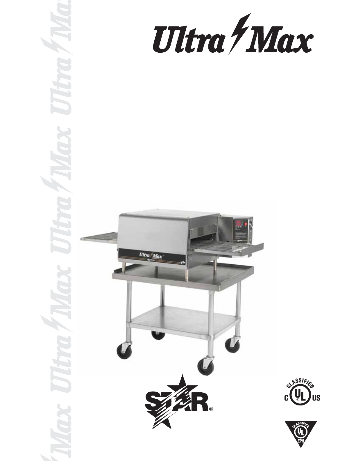
CONVEYOR OVEN
MODEL
UM1833A-208V
UM1833A-240V
UM1850A-208V
UM1850A-240V
Installation and
UM1850A
Operation
Instructions
2M-Z9844 Rev. B 2/9/07
Page 2

SAFETY SYMBOL
Using any part other than genuine Star factory supplied parts relieves the
manufacturer of all liability.
Star reserves the right to change specifi cations and product design without
notice. Such revisions do not entitle the buyer to corresponding changes,
improvements, additions or replacements for previously purchased
equipment.
Due to periodic changes in designs, methods, procedures, policies and
regulations, the specifi cations contained in this sheet are subject to change
without notice. While Star Manufacturing exercises good faith efforts to provide
information that is accurate, we are not responsible for errors or omissions
in information provided or conclusions reached as a result of using the
specifi cations. By using the information provided, the user assumes all risks in
connection with such use.
These symbols are intended to alert the user to the presence of
important operating and maintenance instructions in the manual
accompanying the appliance.
RETAIN THIS MANUAL FOR FUTURE REFERENCE
NOTICE
MAINTENANCE AND REPAIRS
Contact your local authorized service agent for service or required maintenance. Please record the model
number, serial number, voltage and purchase date in the area below and have it ready when you call to
ensure faster service.
Model No.
Serial No.
Voltage
Purchase Date
Authorized Service Agent
Reference the listing provided with the unit
or
for an updated listing go to:
The Star Service Help Desk
Business 8:00 am to 4:30 p.m. Central Standard Time
Hours:
Telephone: (800) 807-9054 Local (314) 781-2777
Fax: (800) 396-2677 Local (314) 781-2714
E-mail [email protected]
Website: www.star-mfg.com
Mailing Address: Star Manufacturing International Inc.
10 Sunnen Drive
St. Louis, MO 63143
U.S.A
2
Page 3
SPECIFICATIONS
UM1833A-208V, UM1833A-240V
Rating/Connection: 6,400 Watts (6,000 element), 32/29 Amps at 208/240V
NEMA 6-50 plus with six foot oil-resistant cord
Electrical Supply: Separate 50 Amp 208/240VAC, single phase, 50/60 Hz service per Oven
Approximate Weight (1833 Oven with Legs): Installed - 180 Lbs (81.8 kg), Shipping - 210 Lbs (95.5 kg)
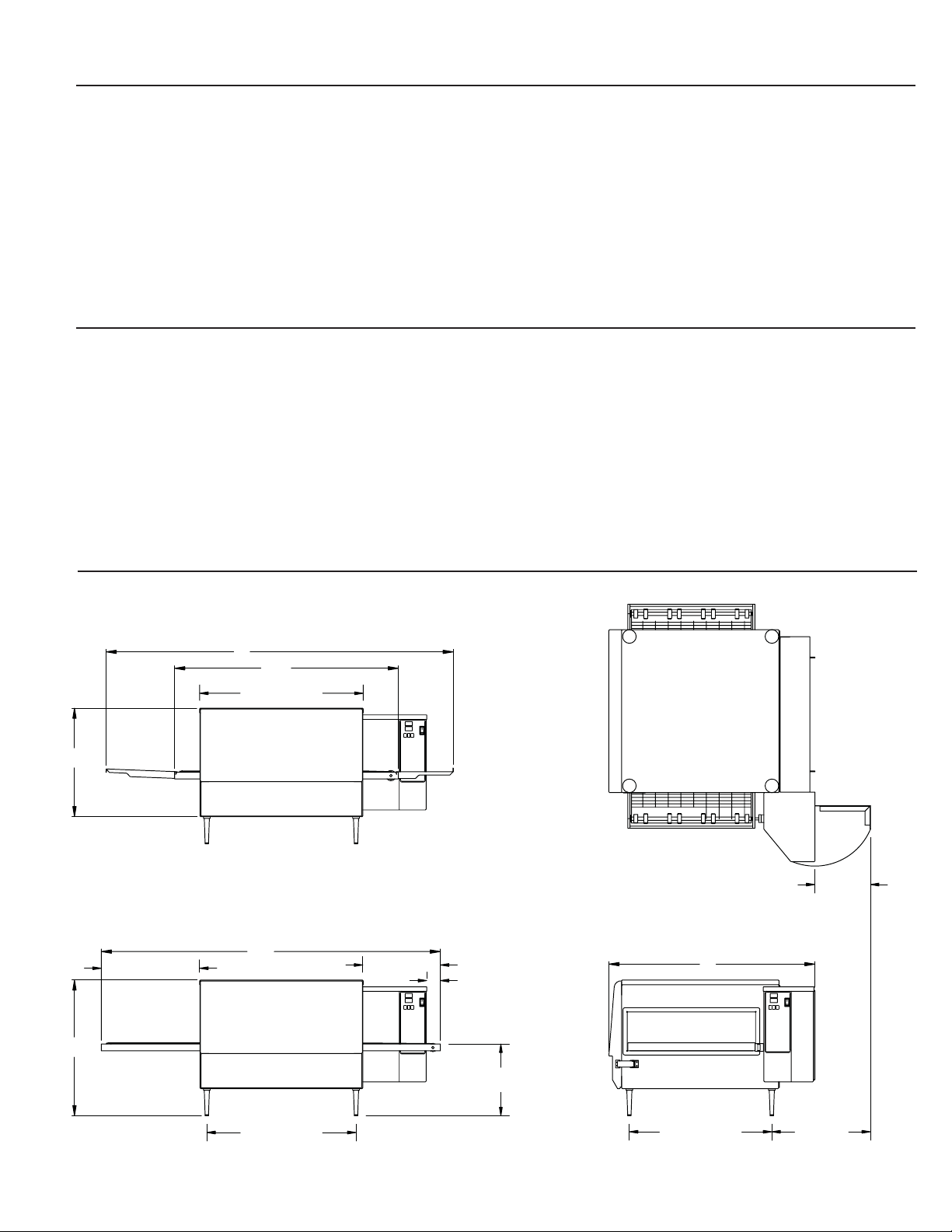
Dimensions: Width: 51.2" (130.0 cm) - Oven with Shelves
Depth: 30.4" (77.2 cm)
Height: 20.0" (50.8 cm) - Single Oven with Legs
36.0" (91.4 cm) - Double Oven with Legs
Recommended Minimum Clearances:
Rear of Oven to Wall 0" (0 cm)
Conveyor Extensions to Wall 6" (15.2 cm)
UM1850A-208V, UM1850A-240V
Rating/Connection: 6,400 Watts (6,000 element), 32/29 Amps at 208/240V
NEMA 6-50 plus with six foot oil-resistant cord
Electrical Supply: Separate 50 Amp 208/240VAC, single phase, 50/60 Hz service per Oven
Approximate Weight (1850 Oven with Legs): Installed - 210 Lbs (95.5 kg), Shipping - 240 Lbs (109.1 kg)
Dimensions: Width: 50.0" (127.0 cm)
Depth: 30.4" (77.2 cm)
Height: 20.0" (50.8 cm) - Single Oven with Legs
36.0" (91.4 cm) - Double Oven with Legs
Recommended Minimum Clearances:
Rear of Oven to Wall 0" (0 cm)
Conveyor Extensions to Wall 6" (15.2 cm)
C
C1
14.5 [369]
UM1833 WITH
INFEED/EXIT SHELVES
A
A2
24.1 [612]
STACKED DIMENSION
= C + C1
UM1850
A1
0
TOP VIEW
1833 W\OUT
SHELVES SHOWN
A = 51.2 (1300)
A1= 50.0 (1270)
A2= 33.0 (838)
B = 30.4 (772)
C = 16.0 (406)
CONTROL BOX
DOOR OPEN
8.2
[208]
C1= 20.0 (508)
11.4 [291]
2.0 [51]
B
00
22.0 [559]
10.6 [269]
2
21.0 [533]
END VIEWFRONT VIEWS
14.5
[369]
Page 4
GENERAL INFORMATION
This equipment is designed and sold for commercial use only by personnel trained and
experienced in its operation and is not sold for consumer use in and around the home nor for
use directly by the general public in food service locations.
First and foremost, each crate should be examined before signing the Bill of Lading to report
any visible damage by the trucker in transit and to account for the proper number of crates.
If there is apparent damage, arrangements should be made to fi le a claim against the carrier.
Interstate Commerce Regulations require that the claim must be initiated by the consignee.
Proper and secure storage facilities should be arranged for the oven(s) if necessary to protect
it from outdoor or damp conditions at all times before installation.
When you have all the crates unloaded, open the crates and remove all plastic covers. Inspect
at once for concealed damage. If anything appears to be damaged, contact the appropriate
persons immediately to fi le a damage claim. After completing this inspection, fi nish unpacking
the oven. Be sure to remove all paper protection and packing material from the unit
prior to heating.
-IMPORTANT-
CAUTION
FOR YOUR SAFETY DO NOT STORE OR USE GASOLINE OR OTHER FLAMMABLE
VAPORS AND LIQUIDS IN THE VICINITY OF THIS OR ANY OTHER APPLIANCE.
INSTALLATION
The ovens are equipped for the voltage indicated on the nameplate mounted on the rear of
the control box. They will operate on alternating current (AC) only. A cord is provided with a
NEMA 6-50 plug. A matching receptacle with 50A supply must be provided.
WARNING
DO NOT CONNECT TO DIRECT CURRENT (DC).
The installation of the electric oven should conform to the:
NATIONAL ELECTRIC CODE AND ALL LOCAL ELECTRIC CODES AND
ORDINANCES AND THE LOCAL ELECTRIC COMPANY RULES AND
REGULATIONS.
PURCHASER'S RESPONSIBILITY
It is the responsibility of the purchaser:
1. To see that the electric services for the oven are installed on site in accordance with the
manufacturer's specifi cations.
2. To unload, uncrate, and install the oven in its proper location and in accordance with this
installation operation manual.
3. T o see that electric services are connected properly by a qualifi ed installer of your choice.
All such connections must be in accordance with applicable code requirements.
4. To arrange for inspection and operation check-out by an authorized service technician.
The warranty becomes effective upon verifi cation of proper installation.
4
Page 5
IMPORTANT SAFETY INFORMATION
Do not attempt to operate the oven until connection of utility service has been fully inspected
by an authorized service technician or a Star Service Representative. This service is required
by Star in order to assist the purchaser in proper start-up of the oven on site. Please note the
specifi c details on the Warranty and make certain that service connections are made to proper
utility services.
The warranty shall not apply if the oven is started up and operated prior to the utilities and oven
being inspected and check-out made by an authorized service technician or a Star Service
Representative.
CAUTION
IMPROPER INSTALLATION, ADJUSTMENT, ALTERATION, SERVICE, OR
MAINTENANCE CAN CAUSE PROPERTY DAMAGE, INJURY, OR DEATH. READ
ALL INSTRUCTIONS THOROUGHLY BEFORE INSTALLING OR SER VICING THIS
EQUIPMENT.
Minimum clearances must be maintained from all walls and combustible materials. Minimum
clearances for this unit should be 0 inches from the rear (rear bumpers provided must be in place)
and 6 inches from both sides. Keep the oven free and clear of all combustible material.
CAUTION
CAUTION
Do not obstruct the ventilation holes in the control panels as these provide cooling air for the
controls.
WARNING
The oven is to be operated only on the type of electricity shown on the specifi cation plate.
INSTALLATION INFORMATION
THE INST ALLA TION INSTRUCTIONS CONT AINED HEREIN ARE FOR THE USE OF
QUALIFIED INST ALLATION AND SERVICE PERSONNEL ONLY. INSTALLA TION OR
SERVICE BY OTHER THAN QUALIFIED PERSONNEL MAY RESULT IN DAMAGE
TO THE OVEN AND/OR INJURY T O THE OPERATOR.
Qualifi ed installation personnel are individuals, a fi rm, a corporation, or a company which either
in person or through a representative are engaged in and responsible for:
1. The installation of electrical wiring from the electric meter, main control box, or service outlet
to the electric appliance.
Qualifi ed installation personnel must be experienced in such work, familiar with all precautions
required, and have complied with all requirements of state or local authorities having
jurisdiction.
LOCATION
The well-planned and proper placement of your oven will result in long-term operator convenience
and satisfactory performance.
It is essential that an adequate air supply to the oven be maintained to provide a suffi cient fl ow
of ventilation air. Follow these guidelines:
1. Place the oven in an area that is free of drafts.
2. Keep the oven area free and clear of all combustibles such as paper, cardboard, fl ammable
liquids, and solvents.
3. Do not place the oven on a curb base or seal to a wall. This will restrict the fl ow of air and
prevent proper ventilation to the blower motors. This condition must be corrected to prevent
permanent damage to the oven.
4. On all models, tripping of the blower motor's thermal overload device indicates an excessive
ambient temperature at the back of the oven. This condition must be corrected to avoid
permanent damage to the oven.
5
Page 6
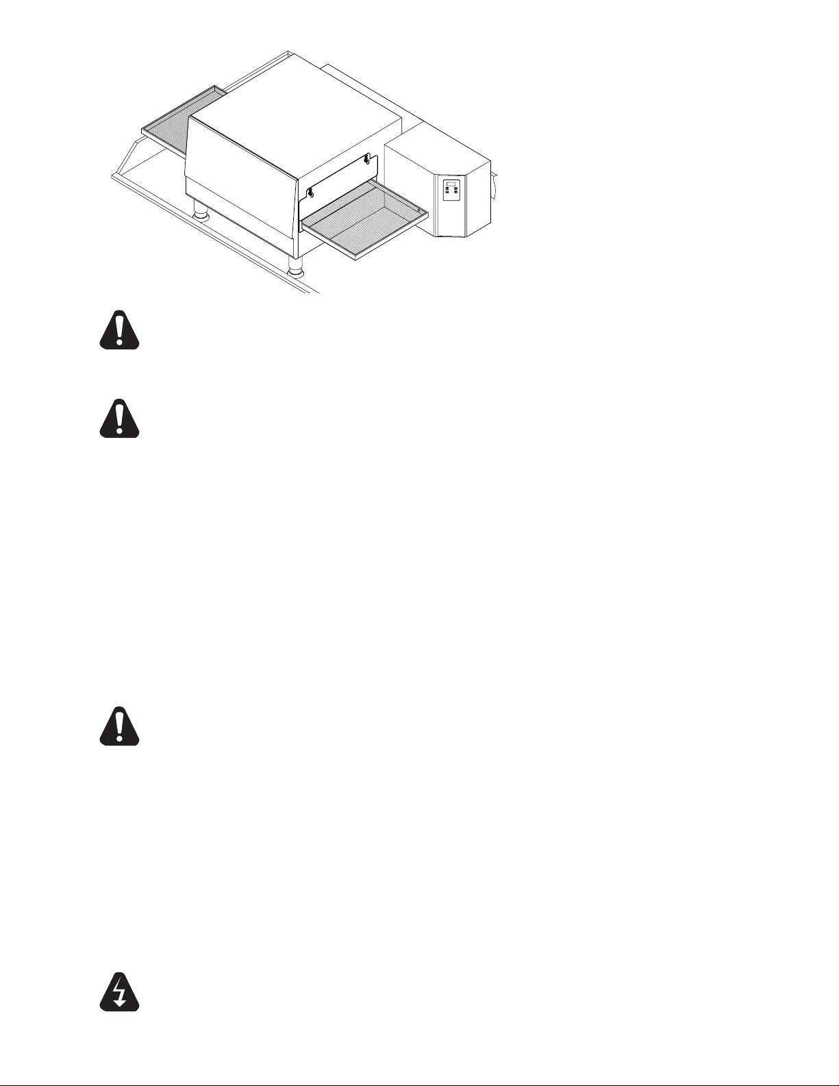
This appliance must be installed on a sturdy
counter or stand using the feet provided
for cleaning clearance. As a minimum, 24"
of clearance on the discharge end of the
oven should be allowed for removal of the
conveyor assembly if the oven is not on a
mobile cart. Also allow room for a service
technician to access the control box door
and the fan motor cover over the rear of the
oven if the oven is not movable.
CAUTION
Any surface the oven is mounted on should have a raised area around the
perimeter to prevent the oven from accidentally sliding off the edge. Serious
injury or death could occur if the oven falls on a person.
CAUTION
Any cart that the oven is mounted on must be deep and wide enough to provide
a stable platform. A cart with a narrow stance could allow the oven to tip over,
causing property damage or serious harm to people.
VENTILATION
Local codes prevail. These are the "authority having jurisdiction" as stated by the National
Fire Protection Association, Inc. in NFPA 96-Latest Edition. For further ventilation information
see below.
A ventilation hood may be required to remove heat and cooking odors. The hood and HVAC
installation must meet local codes to gain approval by the authority having jurisdiction.
Requirements may vary throughout the country depending on the location by city , county, and
state. Obtain information from the authority having jurisdiction to determine the requirements
for your installation. Obtain information and review copies of codes or documents that will
be used to inspect and approve your installation. Your ventilation hood supplier and HVAC
contractor should be contacted to provide guidance.
CAUTION
Prevent airfl ow through the cooking tunnel. Air must NOT be directed onto the
oven's front or rear or to the sides of the cooking area. This can cause incomplete
or uneven baking and increased energy consumption.
ELECTRICAL CONNECTION
Before making any electrical connections to this unit, check that the power supply is adequate
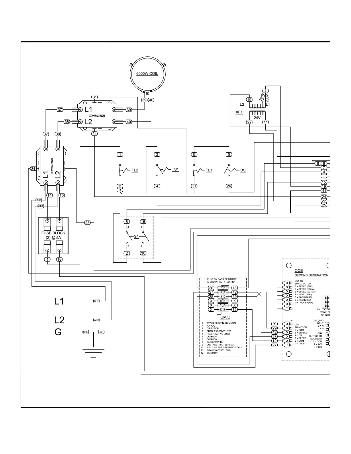
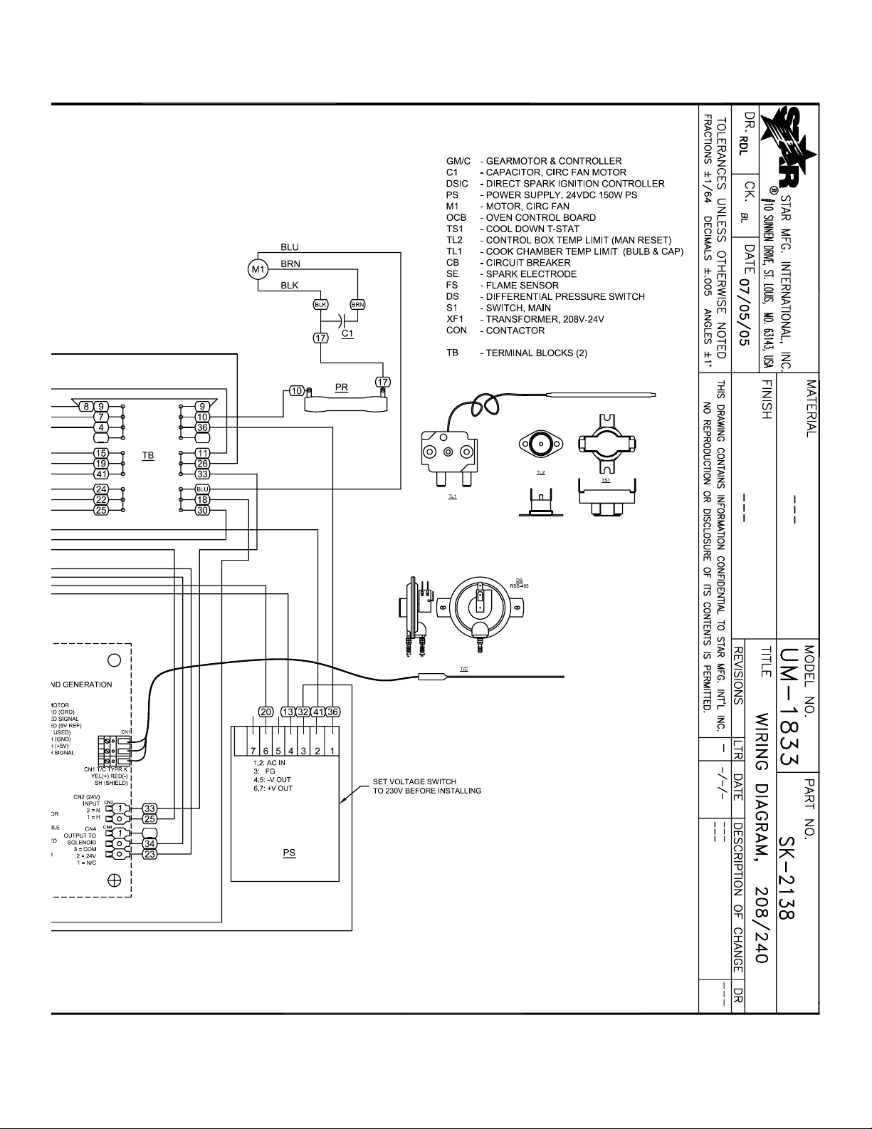
for the voltage, amperage, and phase requirements stated on the rating plate. A wiring diagram
is included herewith.
When installed, this appliance must be electrically grounded and its installation must comply with
the National Electric Code, ANSI-NFP A 70, latest version, manufacturer's installation instructions,
and applicable local municipal building codes. In Canada, all electrical connections are to be
in accordance with CSA C22.1 - Canadian Electrical Code Part 1 and/or local codes.
WARNING
This appliance is equpped with a three-prong (grounding) plug for your protection
against shock hazard and should be plugged directly into a properly grounded threeprong receptacle. Do not cut or remove the grounding prong from this plug.
6
Page 7
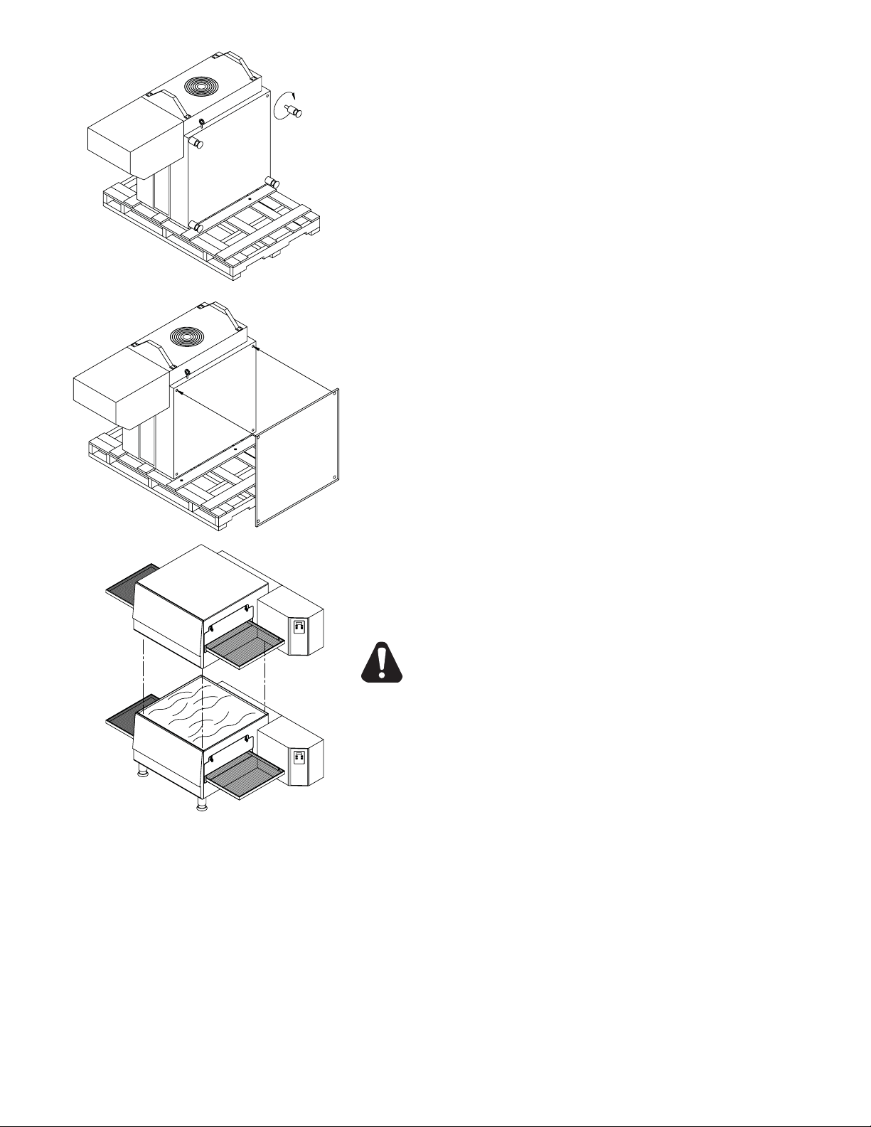
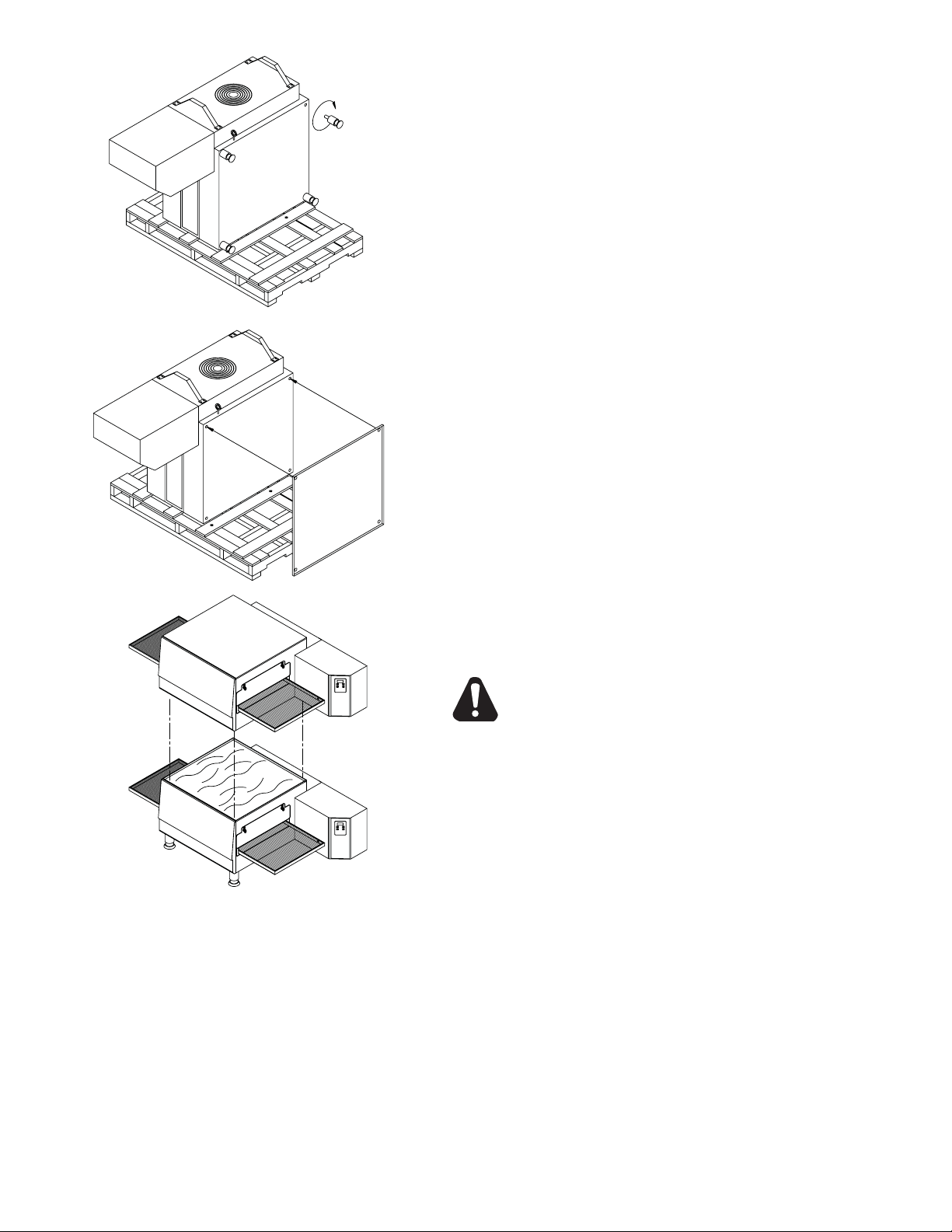
STACKING INSTRUCTIONS
The following instructions should be followed when stacking more
than one unit.
Single Oven (or Bottom) Cart Install:
1. Remove door, conveyor, and fi nger assemblies.
2. Unbolt unit from shipping crate (2 bolts).
3. Turn unit on front as shown.
4. Thread the four legs into the bottom of the oven.
5. CAREFULLY lift oven upright.
Stacked Oven Install Preparation:
1. Remove door, conveyor, and fi nger assemblies.
2. Unbolt unit from shipping crate (2 bolts).
3. Turn unit on front as shown.
4. Remove top of lower oven (4 screws total, 2 each front and rear)
and bolt to stacked oven base using 3/8 - 16 bolts.
5. Place top oven on lower unit and re-attach with screws for top of
lower oven.
OPERATING INSTRUCTIONS
DO NOT ATTEMPT TO OPERA TE THE OVEN until connection of utility
service and installation has been fully inspected (start-up check-out)
by an authorized service technician or a Star Service Technician in
order to assure the oven is properly installed and in working order.
The warranty becomes effective upon verifi cation of proper
installation.
CAUTION
DO NOT WORK AROUND THE CONVEYOR
BELT WITH LONG HAIR, LOOSE CLOTHING, OR
DANGLING JEWELRY. GETTING CAUGHT IN THE
BELT COULD RESULT IN DISMEMBERMENT OR
FATAL INJURY.
Unless specifi ed otherwise, conveyor travel is factory set for left to right operation when facing
the front of the oven. If a direction change is required, refer to "DISPLAY INFORMATION,"
section 3 for instructions on how to program the controller for a direction change. In addition,
the conveyor belt must be changed to travel in the new direction.
SAFETY OPERATING INSTRUCTIONS
The information contained in this section is provided for the use of qualifi ed operating personnel.
Qualifi ed operating personnel are those who have carefully read the information contained in
this manual, are familiar with the functions of the oven and/or have had previous experience
with the operation of the equipment described. Adherence to the procedures recommended
herein will assure the achievement of optimum performance and long, trouble-free service.
7
Page 8
Please take time to read the following safety operating instructions. They are
the key to the successful operation of your Ultra-Max Conveyor Oven.
General Safety Tips:
SAFETY TIPS
For your safety, read before operating.
If you smell gas:
1. DO NOT try to light any appliance.
2. DO NOT touch any electrical switches.
3. Use an exterior phone to call your gas
supplier immediately.
4. If you cannot reach your gas supplier, call
the fi re department.
In the event of a power failure:
1. Turn all switches off.
2. DO NOT attempt to operate the oven until
the power is restored.
1. If the oven needs to be moved for any
reason, the power must be disconnected
from the unit before doing so.
2. DO NOT remove the control box cover
unless the oven is unplugged.
OPERATION
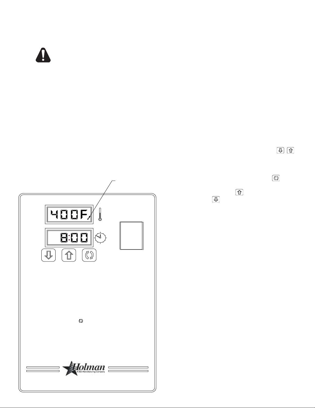
To turn the oven on:
1. Push the power switch to "ON."
2. After the fan begins to build pressure,
the pressure switch will provide power to
the control board to engage the heating
element contactor. You should hear an
initial "click" from the contactor as it begins
to heat.
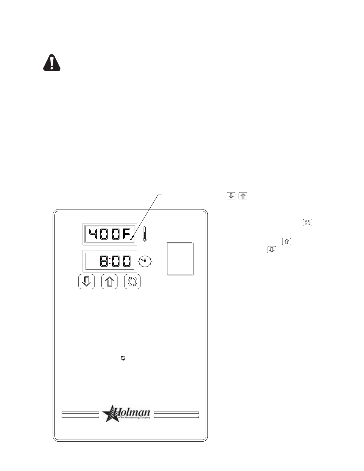
To adjust the time and temperature:
1. Press the DOWN and UP arrows
"HEAT" LIGHT
(
) at the same time. Hold for four
seconds until the TIME display goes
blank.
ON
OFF
To Start:
Push power switch "ON".
If burner does not lght in one minute push the power
switch to the"OFF" position and wait five minutes.
After five minutes, retry.
Adjusting TIME and TEMPERATURE:
1) Press the up and down buttons (
hold for four seconds until TIME display goes blank.
2) Press the enter button ( ) to switch between TIME
and TEMPERATURE.
3) Press the up button (
decrease TIME or TEMPERATURE. Hold button down for
faster display changes.
4) After five seconds, the new numbers will be saved and the oven
will display new settings.
) to increase or the down button (
u
) at the same time,
uv
2. Press the ENTER button (
) to switch
between TIME and TEMPERATURE.
3. Press the UP arrow (
DOWN arrow (
) to increase or the
) to decrease the TIME
or TEMPERATURE. Hold either button
down for faster display changes.
4. After fi ve seconds, the new numbers will
be saved and the oven will display the new
settings.
To turn the oven off:
1. Push the power switch to "OFF." The
oven is equipped with a cool-down feature
for motor shaft and bearing protection.
This enables the blower motor(s) to run
regardless of the controller status. The
blower(s) continue to run until the oven
) to
v
cools to a safe temperature.
®
8
Page 9

DISPLAY INFORMATION
When operating the oven, there are three levels of access:
1. Store Level - General employees would know these functions and how to change them.
While the oven is running, enter this mode by holding the DOWN and UP arrows ( )
simultaneously for four seconds. The TIME display goes blank and the TEMP setpoint is
displayed. Adjust with the DOWN or UP arrows. The ENTER button (
TIME and TEMP. The parameter that can be adjusted is displayed, the other is blank.
When TIME and TEMP are adjusted as needed, wait fi ve seconds and SAVE is displayed.
The values are accepted and the controller begins controlling to these new values. The
conveyor continues to operate at the same speed until a new value is accepted. The
temperature control output should be OFF during changes.
2. Manager Level - This is a lock so that TIME and TEMP cannot be changed even at the Store
Level. While the oven is running, enter this mode by holding the DOWN and UP arrows
simultaneously for 4 seconds. The TIME display goes blank and the TEMP setpoint is
displayed. Release the UP arrow and continue to hold the DOWN arrow for an additional
4 seconds. The TEMP display shows LOC as the TIME display shows nO, which indicates
that the TIME/TEMP parameters can be changed after reaching the STORE level. yES
indicates that the parameters cannot be changed even after entering the STORE level.
The LOC setting can be toggled using the ENTER button (
).
) toggles between
ADDITIONAL FUNCTIONS
The conveyor belt direction and the temperature display can be changed on the conveyor
oven by a qualifi ed technician. To change the belt direction, the technician must reverse the
motor direction and rotate the conveyor belt for proper oven function. A technician can also
change the temperature display from Fahrenheit to Celsius. These changes can be made by
the technician during the start-up/check-out or at a later date.
ERROR CODES
Error codes will display as fl ashing text messages for diagnostic purposes. Any temperature
or thermocouple error should turn the temperature output OFF and leave the conveyor running
at the same speed. The belt error should turn the temperature output OFF. The speed error
should display when the motor is unable to settle at the chosen speed. This might occur if a
fast speed is chosen that the motor is unable to spin fast enough to achieve. The speed signal
output will remain the same but the display will fl ash the error message.
9
Page 10
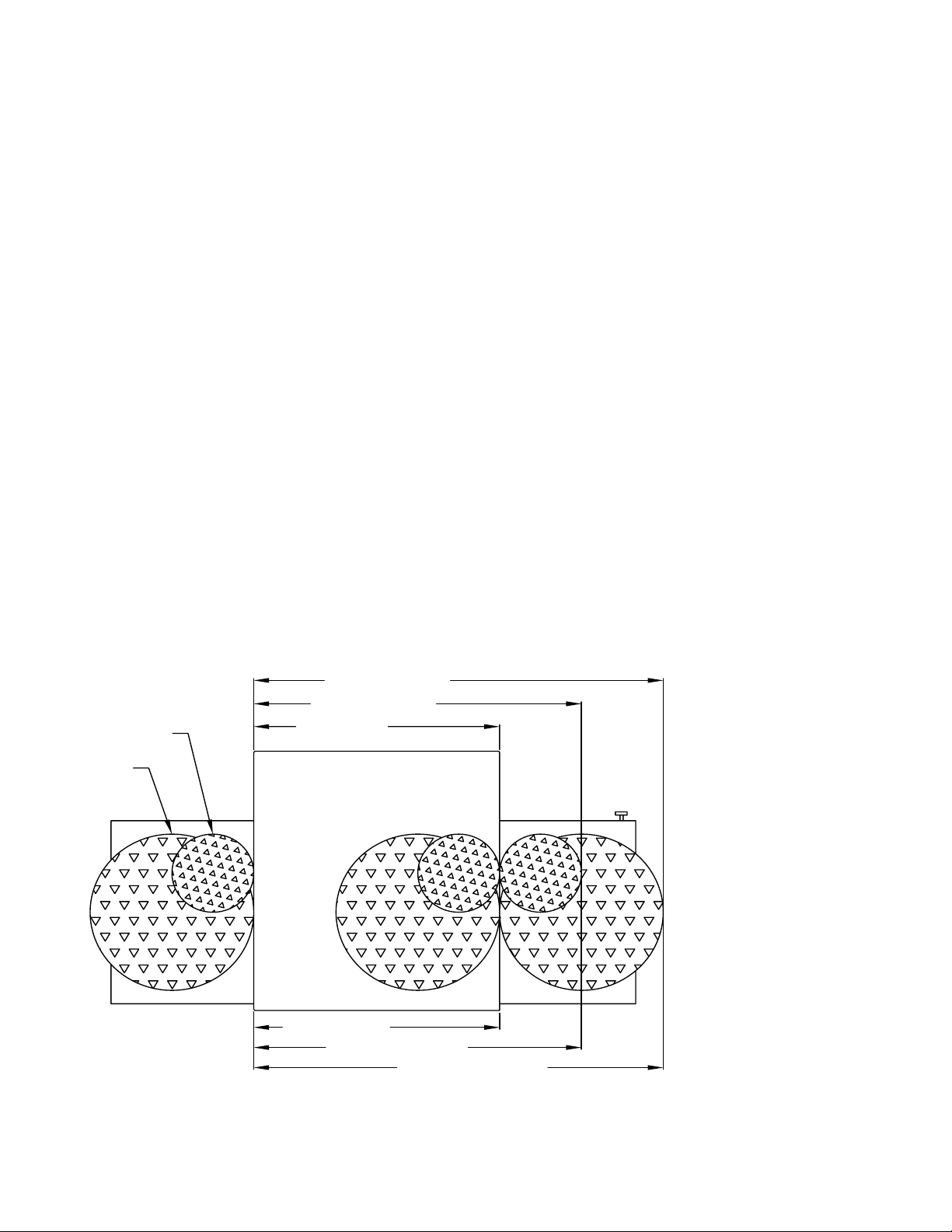
BAKE TIME VERSUS TEMPERATURE
∅=8
∅=16
1. Bake time is actually conveyor speed and is defi ned as the time the product is actually in
the oven. This is measured by noting the time when the leading edge of the product enters
the oven and the time the leading edge of the product leaves the oven. This is adjusted
by using the conveyor speed controller.
2. Bake temperature is adjusted by changing the setpoint of the temperature controller to the
desired bake temperature. When the oven reaches the desired temperature, the red dot
in the lower right corner of the temperature display will turn off and on as the controller
maintains the temperature.
3. When establishing a bake time and temperature for a given product, the general rule shall
be as the bake time increases the bake temperature decreases and the reverse is also true;
increase temperature, decrease time. However, there are limits to the above rule. Going
to extremes will result in a burnt exterior and raw interior or it will result in a very light color
but over-baked product.
4. Once a good bake has been established, the fi ne adjustments should be made by holding
either the bake time or bake temperature constant, then varying the other.
CONVEYOR SPEED
Bake Time (Conveyor Speed) - As stated previously, bake time (conveyor speed) is defi ned as
the amount of time elapsed between the time the leading edge of the product enters the oven
and the leading edge of the product exits the oven. Bake time is controlled by adjusting the
digital speed controller. The setting on the control panel indicates the actual bake time.
Bake time will be the same for any size product.
TIME OF DELIVERY
The time of delivery is the amount of elapsed time between the period when the leading edge
of the product enters the oven and the trailing edge of the product is fully discharged and is
ready to be delivered to the customer.
40 (DELIVERY)
32 (DELIVERY)
24 (BAKE)
Time of delivery
changes if the product
size changes.
Tip: Train yourself not to
pull the product out of the
oven when the leading edge
comes out. Always wait
until the entire product has
passed under the air nozzle
holes - the product needs
this time to fully bake.
6:00 (BAKE)
8:00 (DELIVERY)
10:00 (DELIVERY)
BAKE vs. DELIVERY TIME
Time to Delivery changes with product
but Bake Time remains constant
at a steady conveyor speed.
10
Page 11
CLEANING INSTRUCTIONS
Follow this recommended cleaning schedule for proper oven performance:
CAUTION
DISCONNECT THE POWER SUPPLY BEFORE SERVICING OR CLEANING THIS OVEN.
SAFEGUARD THE POWER SO IT CANNOT BE ACCIDENTALLY RESTORED. FAILURE
TO DO SO COULD RESUL T IN DISMEMBERMENT , ELECTROCUTION, OR FA T AL INJURY.
THERE IS MORE THAN ONE POWER SUPPL Y CONNECTION POINT WHEN OVENS ARE
ST ACKED, SO MAKE SURE THAT ALL SWITCHES ARE IN THE OFF POSITION BEFORE
CLEANING OR MAINTENANCE.
No electrical components should be subjected to moisture. It is therefore important that the
oven is wiped down carefully. NEVER throw buckets of water over the oven or subject it to
pressure washing from a hose or a pressure spray. If water or other liquid is spilled on the
oven, make sure that none of it has entered the control box area before switching the oven
ON. If in doubt, call your service company.
CAUTION
Adhere to the following warnings when cleaning or maintaining your conveyor oven:
1. The oven must be cool. Do not use power cleaning equipment, steel wool, or wire brushes
on stainless steel surfaces.
2. Do not use a caustic or an alkaline base cleaner on the interior of the oven.
This will ruin the aluminized fi nish of the oven interior.
3. When using cleaning solutions, be sure they meet local and national health standards.
DAILY
1. Clean the conveyor belt using a nylon brush. Allow any foreign material to drop into the
crumb pans.
2. Empty and clean the crumb pans. Use a hot water and detergent mix.
Rinse with clean water.
EVERY MONTH
1. Brush and clean the guard on the motor cooling fan.
2. Unplug the oven.
3. Remove the crumb pans.
4. Remove the conveyor assembly.
5. Unlatch and remove the front door. First remove all Baffl es then Finger Assemblies.
See instructions next page.
6. Clean the oven interior with an appropriate oven cleaner.
7. Clean the conveyor assembly, crumb pans, and other removable components.
Wash in a hot water, detergent mix and rinse with clean water. For diffi cult cleaning
areas, use a heavy-duty de-greaser or oven cleaner.
8. Move the oven and clean under it. Be careful not to damage the oven's electrical cord or
plug when moving.
9. Reassemble the oven, being certain to include all Finger Assemblies and the Upper &
Lower Baffl es.
Be certian the Lower Baffl e Flange is properly positioned behind the Rear Oven Wall, as
well as the Upper Baffl e is in position against the Upper Baffl e Seat, as shown.
EVERY TWELVE MONTHS
A factory authorized service person should:
1. Open and clean the inside of the control box.
2. Check and tighten all electrical components.
If maintenance is required, contact your local service company, a factory
representative, or Star Manufacturing.
11
Page 12
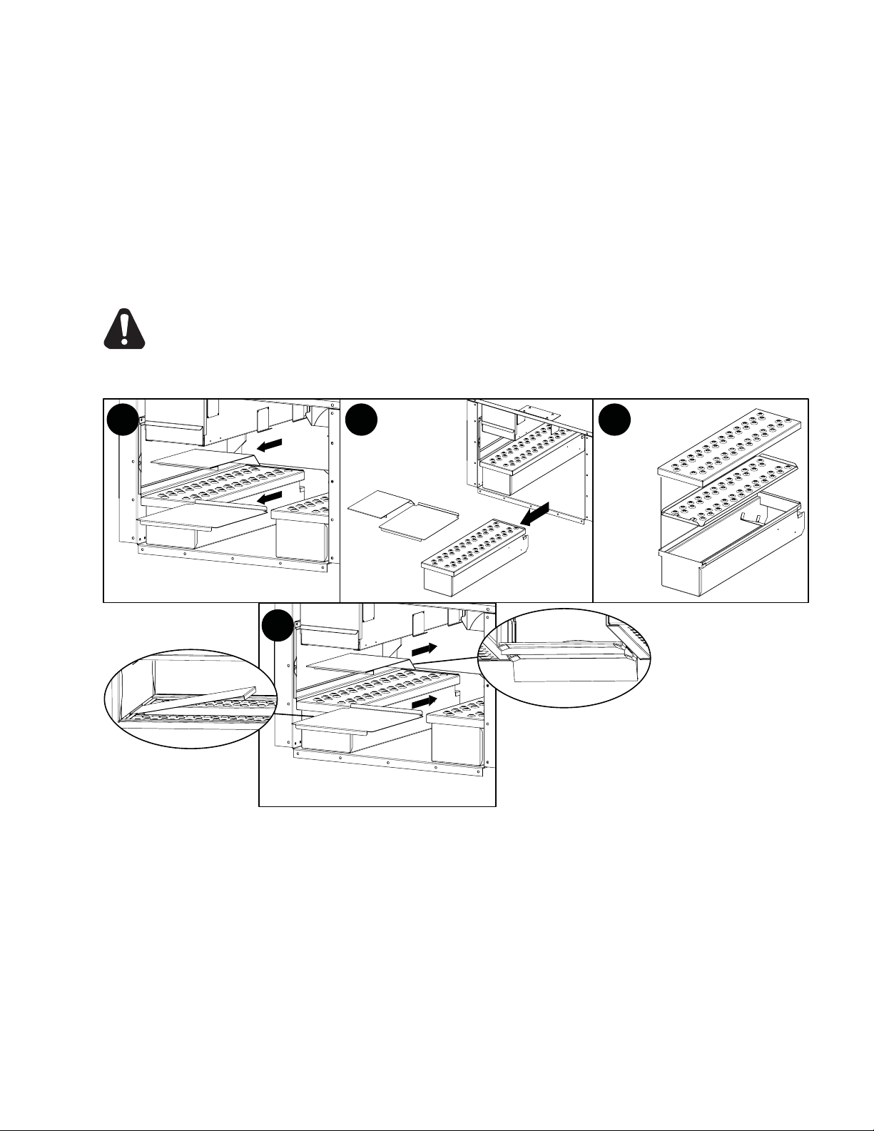
Removing Finger Assemblies
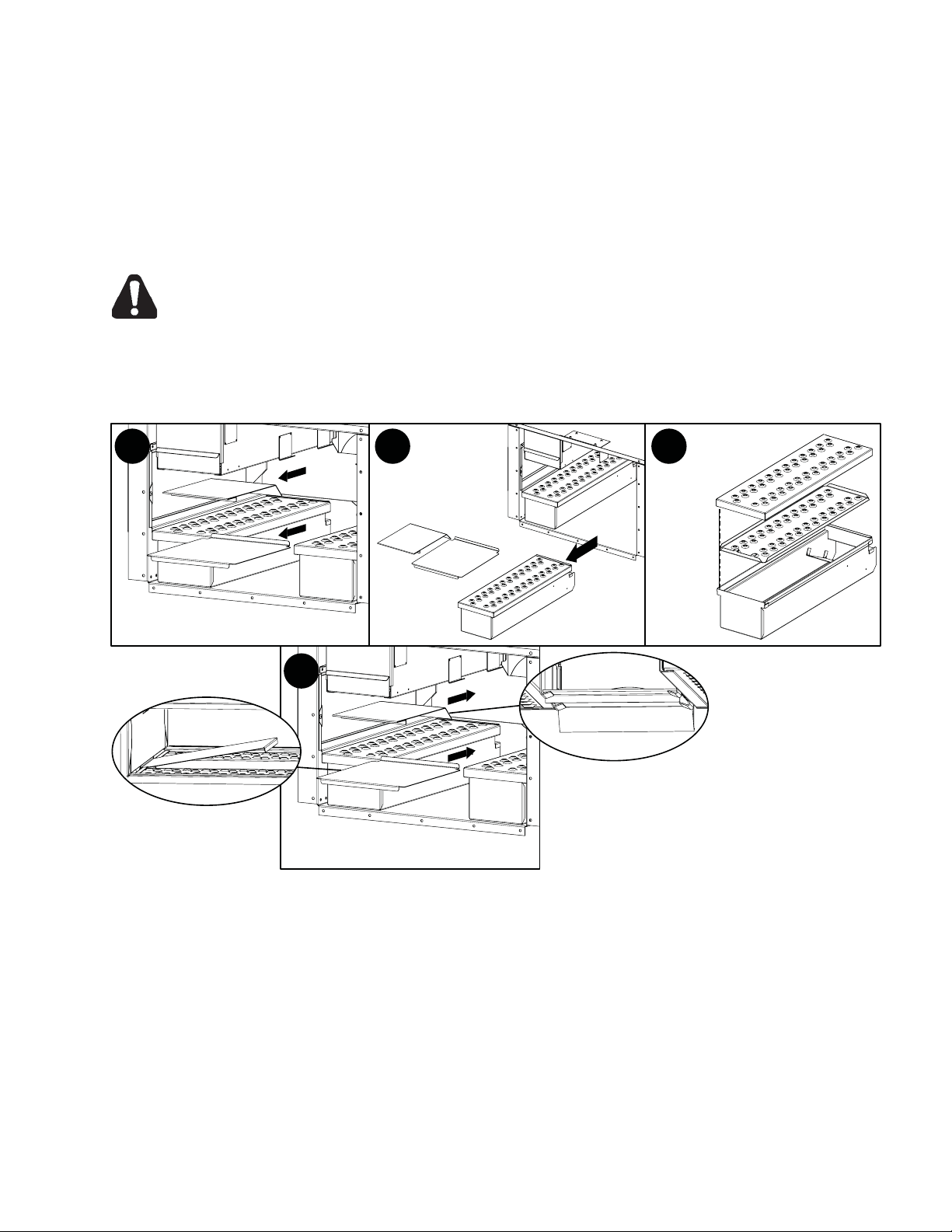
1. Once cooled, REMOVE conveyor assembly and door.
2. Life up and remove Upper & Lower Baffl es as shown in Step 1.
3. Slide Finger Assembly out of unit as shown in Step 2.
4. Lift Assembly apart as shown in Step 3. and wash in a hot water, detergent mix and rinse
with clean water. For diffi cult cleaning areas, use a heavy-duty de-greaser or oven cleaner.
Reassemble Finger Assemblies
1. Reassemble fi nger assemblies and install in unit.
2. Properly install Baffl es as shown in Step 4.
CAUTION
BE CERTAIN THE LOWER BAFFLE IS PROPERLY INSTALLED BEHIND THE REAR
PANEL SO NOT TO INTERFERE OR DAMAGE CONVEYOR ASSEMBLY.
3. Reinstall conveyor & door assembly, and test unit for proper operation.
1 2
4
LOWER BAFFLE
Baffl e & Finger Removal / Installation
3
IL1190
UPPER BAFFLE
12
Page 13
CONVEYOR BELT TENSION
The conveyor belt of the Ultra-Max Conveyor Oven does
not have a tension adjustment. If the belt becomes too
loose, a link will have to be removed to tighten. A belt
that is too tight will also cause operational problems due
to excessive drag. We suggest that you have a qualifi ed
service technician perform this adjustment.
CAUTION
Careful consideration should be exercised prior
to removing a belt link because a belt that is
too tight will impede the smooth operation of
the conveyor.
CONVEYOR BELT LINK REMOVAL
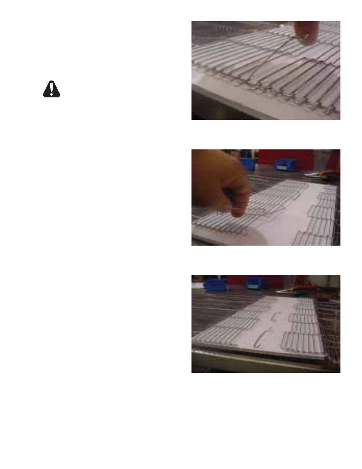
An entire link can be removed with the conveyor assembly
either in or out of the oven. This may be necessary as
the belt stretches after continuous use. Following are
the necessary steps for removing links:
Remove the outside master links on the right and left
sides of the conveyor belt. Remove the center splice
clips next.
1. Move the splice clips to either end of the oven for
easy access.
2. Unhook the splice clips using long nose pliers.
3. Unhook the full link to be removed and slide it out.
Do not discard the link removed as it may be used
for making spare splice clips.
4. Reconnect the inside splice clips.
5. Reconnect the outside splice clips.
6. Replace all parts removed from the oven.
7. Straighten any bent wires to ensure smooth sprocket
engagement.
Unhook the end loop and pull up on the link section.
Save this link as it may be used for making splice
clips.
Check the orientation of the splice clips (the hooks
should be up). The belt shown is the top section,
ready for left-to-right travel.
13
Page 14

Visit our Website at: www.star-mfg.com Email: [email protected]
THOROUGHLY INSPECT YOUR UNIT ON ARRIVAL
This unit has been tested for proper operation before leaving our plant to insure delivery of your unit in perfect condition. However, there are instances in
which the unit may be damaged in transit. In the event you discover any type of damage to your product upon receipt, you must immediately contact the
transportation company who delivered the item to you and initiate your claim with same. If this procedure is not followed, it may affect the warranty
status of the unit.
LIMITED EQUIPMENT WARRANTY
All workmanship and material in Star products have a one (1) year limited warranty on parts & labor in the United States and Canada. Such warranty is
limited to the original purchaser only and shall be effective from the date the equipment is placed in service. Star's obligation under this warranty is limited
to the repair of defects without charge, by the factory authorized service agency or one of its sub-agencies. Models that are considered portable (see below)
should be taken to the closest Star service agency, transportation prepaid.
> Star will not assume any responsibility for loss of revenue.
> On all shipments outside the United States and Canada, see International Warranty.
* The warranty period for the JetStar six (6) ounce & Super JetStar eight (8) ounce series popcorn machines is two (2) years.
* The warranty period for the Chrome-Max Griddles is five (5) years on the griddle surface. See detailed warranty provided with unit.
* The warranty period for Teflon/Dura-Tec coatings is one year under normal use and reasonable care. This warranty does not apply if damage occurs to
Teflon/Dura-Tec coatings from improper cleaning, maintenance, use of metallic utensils, or abrasive cleaners. This warranty does not apply to the
“non-stick” properties of such materials.
> This warranty does not apply to "Special Products" but to regular catalog items only. Star's warranty on "Special Products" is six (6) months on parts
and ninety (90) days on labor.
> This warranty does not apply to any item that is disassembled or tampered with for any purpose other than repair by a Star Authorized Service Center or
the Service Center's sub-agency.
> This warranty does not apply if damage occurs from improper installation, misuse, wrong voltage, wrong gas or operated contrary to the Installation and
Operating instructions.
> This warranty is not valid on Conveyor Ovens unless a "start-up/check-out" has been performed by a Factory Authorized Technician.
PARTS WARRANTY
Parts that are sold to repair out of warranty equipment are warranted for ninety (90) days. The part only is warranted. Labor to replace the part is
chargeable to the customer.
SERVICES NOT COVERED BY WARRANTY
1. Travel time and mileage rendered beyond the 50 mile radius limit
2. Mileage and travel time on portable equipment (see below)
3. Labor to replace such items that can be replaced easily during a daily cleaning
routine, ie; removable kettles on fryers, knobs, grease drawers on griddles, etc.
4. Installation of equipment
5. Damages due to improper installation
6. Damages from abuse or misuse
7. Operated contrary to the Operating and Installation Instructions
8. Cleaning of equipment
9. Seasoning of griddle plates
PORTABLE EQUIPMENT
Star will not honor service bills that include travel time and mileage charges for servicing any products considered "Portable" including items listed below.
These products should be taken to the Service Agency for repair:
* The Model 510FD Fryer.
* The Model J4R, 4 oz. Popcorn Machine.
* The Model 518CMA & 526CMA Cheese Melter.
* The Model 12MC & 15MC & 18MCP Hot Food Merchandisers.
* The Model 12NCPW & 15NCPW Nacho Chip/Popcorn Warmer.
* All Hot Dog Equipment except Roller Grills & Drawer Bun Warmers.
* All Nacho Cheese Warmers except Model 11WLA Series Nacho Cheese Warmer.
* All Condiment Dispensers except the Model HPDE, & SPDE Series Dispenser.
* All Specialty Food Warmers except Model 130R, 11RW Series, and 11WSA Series.
* All QCS/RCS Series Toasters except Model QCS3 & RCS3 Series.
The foregoing warranty is in lieu of any and all other warranties expressed or implied and constitutes the entire warranty.
FOR ASSISTANCE
Should you need any assistance regarding the Operation or Maintenance of any Star equipment; write, phone, fax or email our Service Department.
In all correspondence mention the Model number and the Serial number of your unit, and the voltage or type of gas you are using.
10. Voltage conversions
11. Gas conversions
12. Pilot light adjustment
13. Miscellaneous adjustments
14. Thermostat calibration and by-pass adjustment
15. Resetting of circuit breakers or safety controls or reset buttons
16 . Replacement of bulbs
17. Replacement of fuses
18 . Repair of damage created during transit, delivery, &
installation OR created by acts of God
ALL:
* Pop-Up Toasters
* Butter Dispensers
* Pretzel Merchandisers
* Pastry Display Cabinets
* Nacho Chip Merchandisers
* Accessories of any kind
* Sneeze Guards
* Pizza Ovens
* Heat Lamps
* Pumps
Part# 2M-4497-2 05/06 RB
Page 15

Page 16
Page 17
Page 18
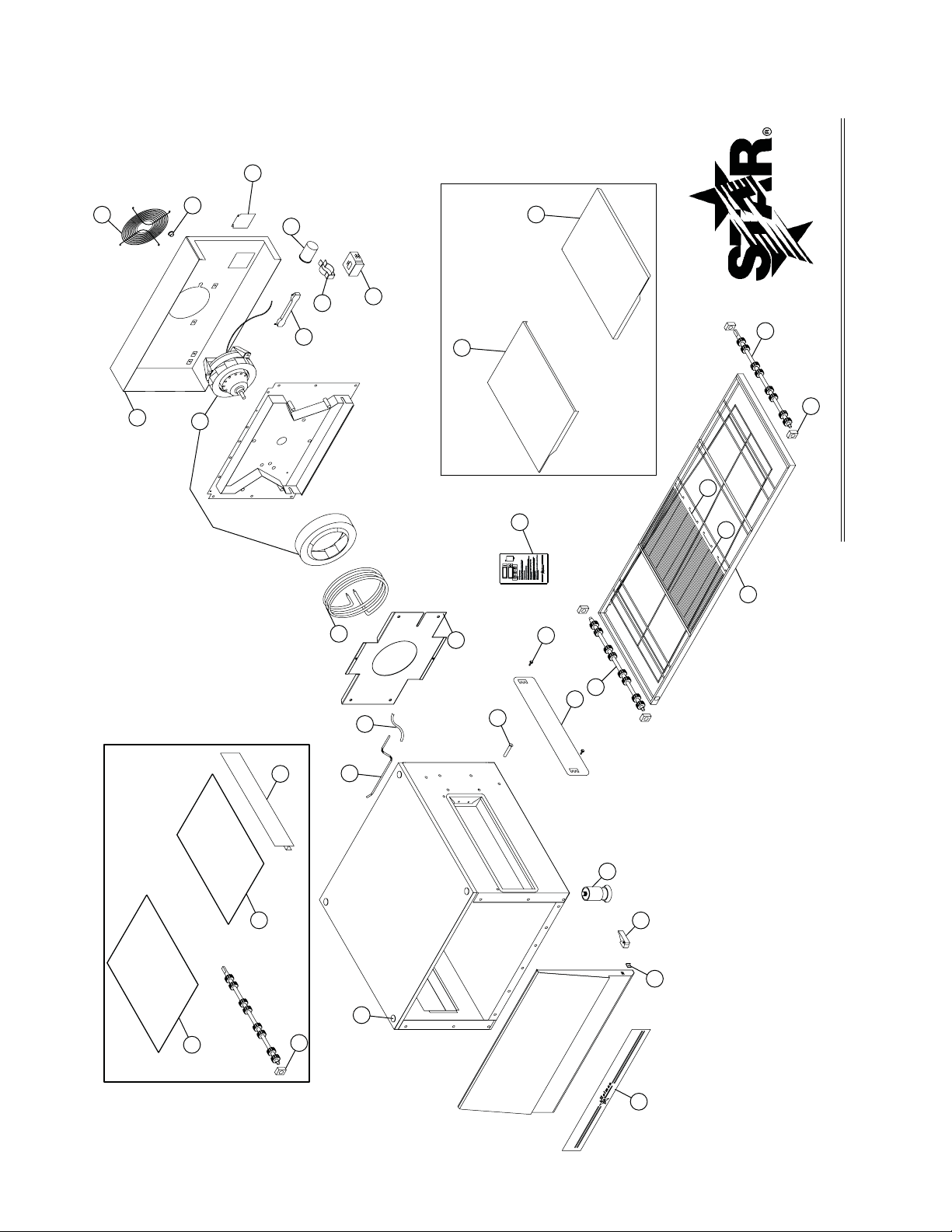
10
9
14
15
20
17
18
19
25
28
27
30
31
22
23
23
1
13
5
8
A Star Manufacturing Company
4) After five seconds, the new numbers will be saved and the oven
will display new settings.
If burner does not lght in one minute push the power
Adjusting TIME and TEMPERATURE:
2) Press the enter button ( ) to switch between TIME
1) Press the up and down buttons (
Ý ß
) at the same time,
hold for four seconds until TEMPERATURE display goes blank.
3) Press the up button (
Ý
) to increase or the down button (
ß
) to
decrease TIME or TEMPERATURE. Hold button down for
switch to the"OFF" position and wait five minutes.
To Start:
Push power switch "ON".
After five minutes, retry.
and TEMPERATURE.
faster display changes.
ON
OFF
6
26
29
34
32
35
33
7
A S
tar
Man
ufa
ctur
ing
Com
pany
2
3
21
NOTE:
CENTER DRIVE SHAFT,
CRUMB TRAYS,
AND PAN STOP
1850 MODEL ONLY
NOTE:
CONVEYOR SHELVES
1833 MODEL ONLY
4
12
11
STAR MANUFACTURING INTERNATIONAL, INC.
MODEL UM1833A / UM1850A
SK2235 REV. - 2/9/07
MAIN ASSEMBL Y
SOME ITEMS ARE INCLUDED FOR ILLUSTRATIVE PURPOSES ONLY AND IN CERTAIN
INSTANCES MAY NOT BE AVAILABLE.
THIS DRAWING CONTAINS INFORMATION CONFIDENTIAL TO STAR MANUFACTURING
INTERNATIONAL, INC. NO REPRODUCTION OR DISCLOSURE OF ITS CONTENTS IS
PERMITTED.
Page 19
PARTS LIST February 9, 2007, Rev. B
Ultra-Max Electric Conveyor Oven
UM1833A/1850A-208/240V - Main Assembly
MODEL
Number
Key
Number
1 G9-Z5716 2 TUNNEL SHROUD
2 G9-Z5745 1 INFEED SHELF
3 G9-Z5362 1 EXIT SHELF
4 2A-Z0314 4 ADJUSTABLE LEG
5 2C-Z5182 4 THUMB SCREW
6 2M-Z5747 1 CONTROL GRAPHIC
7 2M-Z5665 1 FRONT GRAPHIC
8 2P-Z4996 4 VENT PLUG
9 2R-Z5174 2 LATCH
10 2R-Z5188 2 LATCH KEEPER
11 2V-Z6696 1 PRESSURE TUBE
12 G9-Z5574 1 HOSE SECTION
13 2V-Z5789 1 PROBE TUBE
14 G9-EC0025 1 CONVEYOR FRAME UM1833
G9-EC0043 1 CONVEYOR FRAME UM1850
15 2A-Z6538 1 DRIVESHAFT ASSEMBLY W/ SPROCKETS
17 2A-Z5586 1/2 IDLER SHAFT(S) W/ SPROCKETS UM1833 / UM1850
18 2B-Z5709 1 BELT - 6' UM1833
2B-Z5169 1 BELT - 10' UM1850
2B-Z6705 1 COATED BELT - 10' UM1850
19 2B-Z5170 4 BELT SPLICE CLIP
2B-Z6706 4 COATED BELT CLIP UM1850
20 2P-Z5168 4 BEARING
21 2P-Z6368 2 BEARING - DRIVE UM1850
22 G9-Z5281 1 PAN STOP
23 G9-Z6193 2 CRUMB TRAY
25 G9-EC0093 1 FAN BAFFLE ASSY QUAD NOZZ
26 2N-Z5713 1 HEATING ELEMENT - 208V
2N-Z5676 1 HEATING ELEMENT - 240V
27 2U-Z5710 1 HOT AIR BLOWER (Includeds Capacitor)
28 G9-EC0023 1 REAR COVER
29 2E-Z5677 1 POWER RESISTOR, 75ohm 240V
2E-Z6630 1 POWER RESISTOR, 50ohm 208V
NI 2E-Z5663 2 POWER RESISTOR BRACKETS
30 2B-Z5607 1 REAR FAN GUARD
31 2K-Z2895 1 SPLIT BUSHING
32 G9-Z5772 1 ACCESS DOOR
33 2E-Z5711 1 MOTOR CAPACITOR, Service Only
34 2E-Z5742 2 CONTACTOR, 40 AMP, 24VAC
35 2C-Z5195 1 CONDUIT HANGER
Part
Number
Per
Unit
Description and Model Designation
1
IMPORTANT: WHEN ORDERING, SPECIFY VOLTAGE OR TYPE GAS DESIRED PAGE
1
INCLUDE MODEL AND SERIAL NUMBER OF
Some items are included for illustrative purposes only and in certain instances may not be available.
Star Manufacturing International, Inc.
Page 20
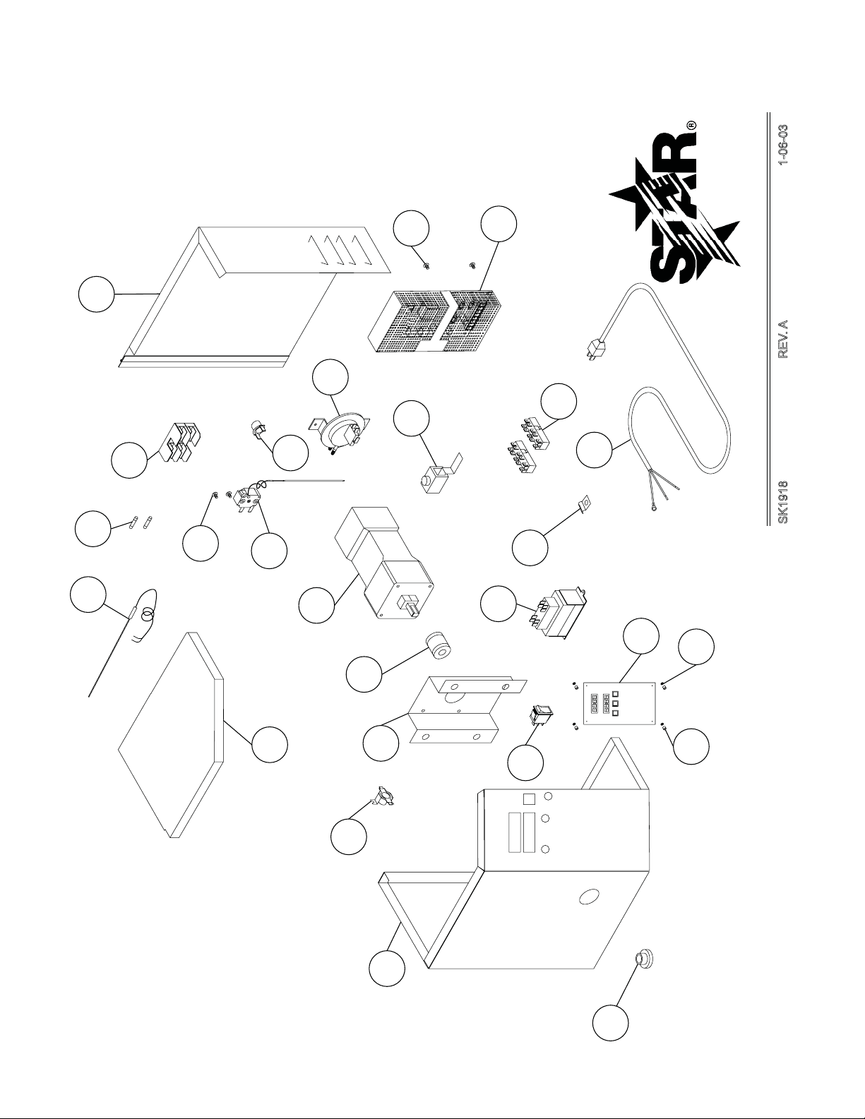
21
10
2
23
9
24
17
7
6
4
12
14
26
1
2
3
4
5
6
7
8
16
1
SK1918 REV. A 1-06-03
STAR MANUFACTURING INTERNATIONAL, INC.
25
18
3
20
(4)
MODEL UM1833
11
5
13
24
8
22
19
CONTROL BOX ASSEMBLY
INSTANCES MAY NOT BE AVAILABLE.
THIS DRAWING CONTAINS INFORMATION CONFIDENTIAL TO STAR MANUFACTURING
INTERNATIONAL, INC. NO REPRODUCTION OR DISCLOSURE OF ITS CONTENTS IS
PERMITTED.
SOME ITEMS ARE INCLUDED FOR ILLUSTRATIVE PURPOSES ONLY AND IN CERTAIN
Page 21
PARTS LIST February 9, 2007, Rev. B
Ultra-Max Electric Conveyor Oven
UM1833A/1850A-208/240V - Control Box
MODEL
Number
Key
Number
1 2E-Z5798 1 CORD SET 208V, 50A
2 G9-EC0014 1 CONTROL BOX DOOR ASSEMBLY
3 G9-Z7280 1 CONTROLLER, TIME / TEMPERATURE STD (°F)
G9-Z7283 1 CONTROLLER, TIME / TEMPERA TURE X/CE (°C)
4 2E-Z5683 1 VACUUM LIMIT SWITCH (Contact Service if replacing 2E-Z5180)
5 2T-Z5175 1 THERMOSTAT, 120°F
6 2T-Z5176 1 THERMOSTAT, 140°F
7 2T-Z5177 1 HIGH TEMPERA TURE LIMIT THERMOSTAT
8 2E-Z1858 1 SWITCH - LIGHTED
9 2J-Z5189 1 THERMOCOUPLE ASSEMBLY
10 G9-Z6610 1 POWER SUPPLY, 24VDC-150W (230V INPUT)
11 G9-Z5738 1 LID, CONTROL BOX
12 2U-Z5171 1 GEARMOTOR
13 G9-Z5740 1 GEARMOTOR BRACKET
14 2A-Z6534 1 COUPLING, SPRING LOADED
15 2B-Z5775 2 FAN WIRE GUARD
16 2E-Z4597 2 TERMINAL BLOCK
17 2C-Z0216 2 SCREW M4 (METRIC)
18 2E-Z5741 1 TRANSFORMER
19 2K-Z1971 4 SPACER
20 2C-Z5427 6 NYLON SPACER
21 2C-Z5797 2 SCREW M3 (METRIC)
22 2K-3485 1 BUSHING - HEYCO
23 2E-Z5680 2 FUSE
24 2E-Z5681 1 FUSEHOLDER
25 2C-Z3350 1 HALF CLAMP
26 2C-Y2344 1 GROUND TERMINAL
Part
Number
Per
Unit
Description
1
IMPORTANT: WHEN ORDERING, SPECIFY VOLTAGE OR TYPE GAS DESIRED PAGE
1
INCLUDE MODEL AND SERIAL NUMBER OF
Some items are included for illustrative purposes only and in certain instances may not be available.
Star Manufacturing International, Inc.
Page 22
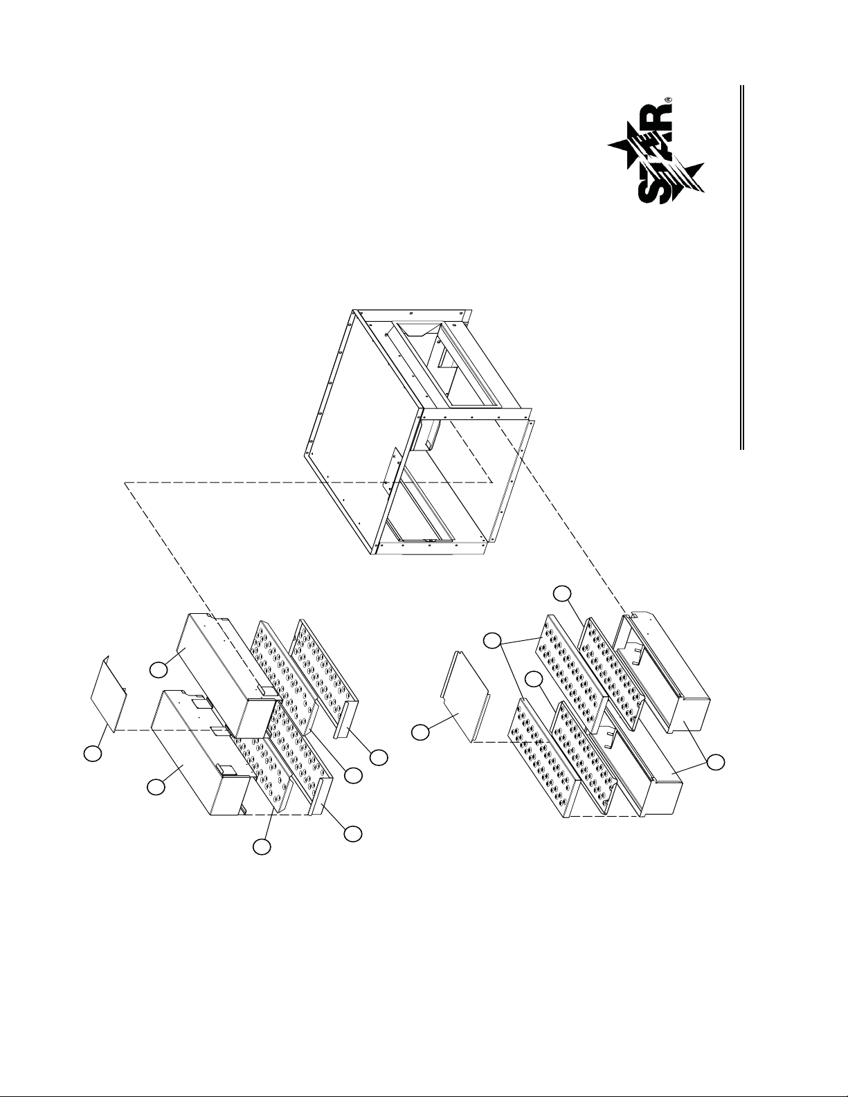
SK2208 REV. - 6/14/06
STAR MANUFACTURING INTERNATIONAL, INC.
8
7
3
8
6
1
5
9
4
2
5
4
UM1800 Series Quad Finger Assembly
CERTAIN INSTANCES MAY NOT BE AVAILABLE
ILLUSTRATIVE PURPOSES ONLY AND IN
SOME ITEMS ARE INCLUDED FOR
No reproduction or disclosure of its
to Star Manufacturing International, Inc.
This drawing contains information confidential
contents is permitted.
MODEL:
Page 23
PARTS LIST February 9, 2007, Rev. B
Ultra-Max Electric Conveyor Oven
UM1833A/1850A-208/240V - Finger Assembly
MODEL
Number
Key
Number
1 G9-Z9196 1 UPPER BAFFLE
2 G9-EC0084 1 FINGER WELD, UPPER LEFT
3 G9-EC0085 1 FINGER WELD, UPPER RIGHT
4 G9-Z9123 2 TOP COLUMNATING PLATE - QUAD
5 G9-Z9121 2 TOP NOZZLE - QUAD
6 G9-Z9197 1 LOWER BAFFLE
7 G9-Z9122 2 BOTTOM NOZZLE - QUAD
8 G9-Z9124 2 BOTTOM COLUMNATING PLATE - QUAD
9 G9-EC0083 2 FINGER WELD, LOWER - QUAD
Part
Number
Per
Unit
Description
1
IMPORTANT: WHEN ORDERING, SPECIFY VOLTAGE OR TYPE GAS DESIRED PAGE
1
INCLUDE MODEL AND SERIAL NUMBER OF
Some items are included for illustrative purposes only and in certain instances may not be available.
Star Manufacturing International, Inc.
Page 24
TENSION DE COURROIE DE CONVOYEUR
La bande de conveyeur du Ultra-Max Convoyeur
Four n'a pas un ajustement de tension. Si la ceinture
devient trop lâche, un lien devra être enlevé pour serrer.
Une ceinture qui est volonté trop serrée également
posent des problèmes opérationnels dus à la drague
excessive. Nous proposons que vous fassiez effectuer
à un technicien qualifi é de service cet ajustement.
La considération soigneuse devrait être exercée
avant d'enlever un lien de ceinture parce qu'une
ceinture qui est volonté trop serrée empêchent
l'opération du convoyeur.
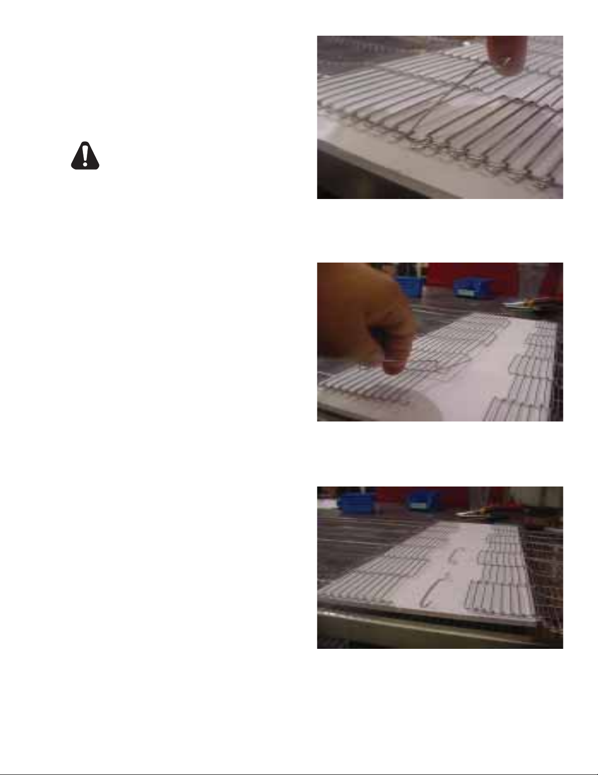
DÉPLACEMENT D'UN BANDE DE CONVEYEUR
Un lien entier peut être enlevé avec le convoyeur dans
ou hors du four. Ceci peut être nécessaire pendant que
la ceinture s’étend après utilisation continue. Suivre les
étapes nécessaires pour des liens d’enlèvement:
1. Déplacez les épissure attaches à n'importe quelle
extrémité du four pour l'accès facile.
2. Décrochez les épissure attaches en utilisant de
longues nez pinces.
3. Décrochez le plein lien à enlever et glissez-le
dehors. Ne jetez pas le lien enlevé en tant que
lui peut être employé pour faire des rechange
épissure attaches.
4. Rebranchez les épissure attaches d'intérieur.
5. Rebranchez les épissure attaches d’extérieur.
6. Remplacez toutes les pièces enlevées du four.
7. Pour assurer l'enclenchement doux de pignon,
rendez tous les fi ls égaux.
ATTENTION
Enlevez les maillons de jonction extérieurs des côtés
gauches et droits de la conveyeur bande. Enlevez les
centrales épissure attaches après.
Décrochez la boucle extrémité et tirez vers le haut sur
la section de lien. Économiser ce lien comme il peut
être employé pour faire des épissure attaches.
13
Vérifi ez l'orientation des épissure attaches (les
crochets devraient être vers le haut). La ceinture
montrée est la section supérieure, préparent pour le
voyage de gauche à droite.
Page 25
Enlever les ensembles de doigt.
1. Une fois refroidi, ENLEVEZ le convoyeur et la porte.
2. Soulevez et enlevez les défl ecteurs du haut et du bas comme le démontre en étape 1.
3. Glissez l’ensemble de doigt hors de l’appareil comme le démontre en étape 2.
4. Soulevez l’ensemble comme le démontre en étape 3 et lavez dans un mélange de l’eau
chaude et du détergent et rincez avec de l’eau propre. Pour les endroits très sales, employez
un dégraissent fort ou un nettoyant four.
Assembler les ensembles de doigt
1. Assemblez les ensembles de doigt et installez dans l’appareil.
2. Montez correctement les défl ecteurs comme le démontre en étape 4.
MISE EN GARDE
ASSUREZ-VOUS QUE LE DÉFLECTEUR DU BAS EST MONTÉ CORRECTEMENT DERRIERE
LE PANNEAU ARRIÈRE POUR ÈVITER LE DOMMAGE AU CONVOYEUR.
3. Remontez le convoyer et la porte et essayez l’appareil.
1 2
4
DÉFLECTEUR DU BAS
Enlever / Monter les défl ecteurs et les doigts
3
IL1190
DÉFLECTEUR DU HAUT
12
Page 26
INSTRUCTIONS D’ENTRETIEN
Suivez ces recommandations pour nettoyer et maintenir votre four:
DÉBRANCHEZ LA PUISSANCE AVANT D’ENTRETENIR OU NETTOYER LE FOUR.
SAUVEGARDEZ LA PUISSANCE AINSI ELLE NE PEUT PAS ÊTRE ACCIDENTELLEMENT
RECONSTITUÉE. LE DÉMEMBREMENT, L’ELECTROCUTION, OU LA MORT PEUVENT
SE PRODUIRE SI VOUS NE COUPEZ PAS LE COURANT. QUAND DES FOURS SONT
EMPILÉS IL Y A LES RACCORDEMENTS DE PUISSANCE MULTIPLES, AINSI ARRÊTEZ
TOUS LES FOURS AVANT LE NETTOYAGE OU L’ENTRETIEN.
Aucun composant électrique ne devrait être soumis à l’humidité. Il est donc important que le
four soit essuyé soigneusement. Ne jetez jamais les seaux d’eau au-dessus le four ou jetez
de l’eau sous pression d’un boyau d’arrosage ou d’un laveuse à pression.. Si on renverse
de l’eau ou d’autre liquide sur le four, assurez-vous qu’aucune n’est entrée dans la boîte de
commande avant de brancher le four. En cas de doute, appelez votre compagnie de service.
Adhérez aux avertissements suivants en nettoyant ou en maintenant votre four:
1. Le four doit être refroidi. N’employez pas l’équipement de nettoyage de puissance, les
laines en acier, ou les brosses métalliques sur des surfaces d’acier inoxydable.
2. N’employez pas de nettoyant caustique alcalin dans l’intérieur du four. Ceci ruinera la
couche aluminisée de l’intérieur du four.
3. En utilisant des solutions de nettoyage, soyez sûr qu’elles répondent à des normes locales
et nationales de santé.
CHAQUE JOUR
1. Nettoyez la bande de convoyeur en utilisant une brosse en nylon. Permettez à n’importe
quel matériel étranger de se laisser tomber dans les plateaux à miettes.
2. Nettoyez les plateaux à miettes. Employez un mélange de l’eau chaude et du détergent.
Rincez avec de l’eau propre.
ATTENTION
ATTENTION
CHAQUE MOIS
1. Brossez et nettoyez la garde sur le ventilateur de moteur.
2. Débranchez le four.
3. Enlevez les plateaux à miettes.
4. Enlevez le convoyeur.
5.. Déclenchez et enlevez la porte avant. D’abord, enlevez tous les défl ecteurs et les ensembles
de doigt. Voir les instructions à la page suivante.
6. Nettoyez l’intérieur de four avec un nettoyant four approprié.
7. Nettoyez le convoyeur, les plateaux à miettes, et d’autres composants démontables. Lavez
dans un mélange de l’eau chaude et du détergent et rincez avec de l’eau propre. Pour des
zones diffi ciles à nettoyer, employez un dégraissent fort ou un nettoyant four.
8.. Déplacez le four et nettoyez au-dessous l’appareil. Assurez-vous de ne pas endommager
le cordon ou les connecteurs électriques.
9. Rassemblez le four, assurez-vous d’inclure tous les ensembles de doigt et les défl ecteurs
du bas et du haut. Assurez-vous de mettre en position la collerette du défl ecteur du bas
correctement derrière le panneau arrière du four et mettre en position le défl ecteur du haut
contre le siège du défl ecteur du haut, comme le démontre.
TOUS LES DOUZE MOIS
Une personne de service autorisée par usine devrait faire ce qui suit:
1. Ouvrez et nettoyez l’intérieur de la boîte de commande.
2. Vérifi ez et serrez tous les composants électriques.
Si l’entretien est exigé, entrez en contact avec votre compagnie de service locale, un représentant
d’usine, ou Star Manufacturing.
11
Page 27

TEMPS DE CUISINIER CONTRE LA TEMPÉRATURE DE CUISINIER
1. Le temps de cuisinier est réellement vitesse de convoyeur et est défi ni car le temps le
produit est réellement dans le four. Ceci est mesuré en notant le moment où le principal
bord du produit entre dans le four et le temps le principal bord du produit part du four. Ceci
est ajusté en employant le contrôleur de vitesse de convoyeur.
2. La température est ajustée en changeant le setpoint du contrôleur de température en
désiré font la température au four cuire. Quand le four atteint la température désirée, le
point rouge dans le bon coin inférieur de l'affi chage de la température s'allumera au loin
et comme le contrôleur maintient la température.
3. En établissant un temps de cuisinier et une température pour un produit, la règle générale est
que quand le temps de cuisinier augmente la température diminue. L'inverse est également
vrai: Augmentez la température, diminuez le temps. Cependant, il y a des limites à la règle
ci-dessus. La trop de chaleur ou temps peut avoir comme conséquence un produit brûlé.
4. Une fois un bon cuisinier a été établi, les ajustements fi ns devrait être fait en jugeant le temps
de cuisinier ou la constante de la température de cuisinier, changeant alors l’autre.
VITESSE DE CONVOYEUR
Temps de Cuisinier (Vitesse De Convoyeur) - Comme indiqué précédemment, le cuisinier que
le temps (vitesse de convoyeur) est défi ni comme la quantité de temps s’est écoulée entre le
moment le principal bord du produit écrit le four et le principal bord du produit sort le four. Le
temps de cuisinier est commandé en ajustant le contrôleur numérique de vitesse. L’arrangement
sur le panneau de commande indique le temps réel de cuisinier.
Le temps de cuisinier sera le même pour n’importe quel produit de taille.
TEMPS DE LA LIVRAISON
La temps de la livraison est la quantité de temps écoulé entre la période où le principal bord
du produit entre dans le four et le rebord arrière du produit est entièrement déchargé et est
prêt à être livré au client.
La temps de la livraison change si la taille de produit change.
Note: Rappelez-vous de ne
pas tirer le produit hors du
four quand le principal bord
sort. Attendez toujours
jusqu'à ce que le produit
entier ait passé sous les
trous d'air - les besoins de
produit cette fois de faire
cuire entièrement.
10
Page 28

L’INFORMATION D’AFFICHAGE
En actionnant le four, il y a trois niveaux d’accès:
1. Stockez De Niveau - Les employés généraux sauraient ces fonctions et comment les changer. Tandis
que le four fonctionne, entrez ce mode en tenant la DUNE et LEVEZ les fl èches (
pendant quatre secondes. L’affi chage de TEMPS va blanc et le setpoint de la TEMPÉRATURE est montré.
Ajustez avec la DUNE ou LEVEZ les fl èches. Le bouton de ENTREZ (
la TEMPÉRATURE. Le paramètre qui peut être ajusté est montré, l’autre est blanc. Quand le TEMPS
et la TEMPÉRA TURE sont ajustés comme nécessaires, attendez cinq secondes et ÉCONOMISER est
montré. Les valeurs sont acceptées et le contrôleur commence à commander à ces nouvelles valeurs.
Le convoyeur continue à fonctionner à la même vitesse jusqu’à ce qu’une nouvelle valeur soit acceptée.
Le rendement de commande de température devrait être arrêté pendant les changements.
2. Niveau De Directeur - C'est une serrure de sorte que le TEMPS et la TEMPÉRATURE ne puissent
pas être changés même au "Stockez de Niveau." Tandis que le four fonctionne, entrez ce mode en
tenant la DUNE et LEVEZ les fl èches (
de TEMPS va blanc et le setpoint de la TEMPÉRATURE est montré. Libérez la fl èche LEVEZ (
) et continuez à maintenir la fl èche DUNE ( ) pendant encore 4 secondes. L'affi chage de la
TEMPÉRATURE montre "LOC" pendant que l'affi chage de TEMPS montre "nO," ce qui indique
que les paramètres de TEMPS/TEMPERATURE peuvent être changés aprèsatteinte du "Stockez
de Niveau." "yES" indique que les paramètres ne peuvent pas être changés même après entrez le
"Stockez de Niveau." L'arrangement de "LOC" peut être basculé utilisant le bouton de ENTREZ (
FONCTIONS ADDITIONNELLES
La direction de bande de conveyeur et l’affi chage de la température peuvent être changés sur le
four de convoyeur par un technicien qualifi é. Pour changer la direction de ceinture, le technicien
doit renverser la direction de moteur et tourner la bande de conveyeur pour la fonction appropriée
de four. Un technicien peut également changer l’affi chage de la température de Fahrenheit en
Celsius. Ces changements peuvent être faits par le technicien pendant le start-up/check-out ou à
une date ultérieure.
) simultanément pendant quatre secondes. L’affi chage
) bascule entre le TEMPS et
) simultanément
).
CODES D’ERREUR
Les codes d’erreur montreront en tant que messages de clignotant des textes pour des buts diagnostiques.
La n’importe quelle température ou erreur de thermocouple devrait tourner la température produite au loin
et laisser le convoyeur fonctionnant à la même vitesse. L’erreur de ceinture devrait tourner la température
produite au loin. L’erreur de vitesse devrait montrer quand le moteur ne peut pas arranger à la vitesse
choisie. Ceci pourrait se produire si on choisit une vitesse rapide que le moteur ne peut pas tourner assez
rapidement pour réaliser. Le rendement de signal de vitesse demeurera le même mais l’affi chage clignotera
le message d’erreur.
9
Page 29
Veuillez prendre du temps de lire les consignes
d’utilisation de sûreté suivante. Elles sont la clef à
l’opération réussie de votre four de convoyeur de
Ultra-Max.
TIP DE SÛRETÉ
Bouts Généraux De Sûreté:
1. Si le four doit être déplacé pour n’importe quelle
raison, le électricité doit être arrêté et démonté à
partir de l’unité.
2. N’enlevez pas la couverture de boîte de commande
à moins que le four soit débranché.
Pour votre sûreté, lisez avant l’opération.
Si vous sentez le gaz:
1. N’essayez pas de n’allumer aucun appareil.
2. Ne touchez aucun commutateur électrique.
3. Utilisez un téléphone extérieur pour appeler votre
fournisseur de gaz immédiatement.
4. Si vous ne pouvez pas atteindre votre fournisseur
de gaz, appelez le département de feu.
En cas d’une panne de courant:
1. Arrêtez tous les commutateurs.
2. N’essayez pas d’actionner le four jusqu’à ce que la
puissance soit reconstituée.
"HEAT" LIGHT
ON
OPÉRATION
Pour allumer le four:
1. Poussez le commutateur de puissance à
"MARCHE."
2. Après que le ventilateur commence à établir la
pression, le mano-contact fournira la puissance
au tableau de commande d'engager le conjoncteur
élément de chauffe. Vous devriez entendre un
"click" en conjoncteur pendant qu'il commence à
chauffer.
Pour ajuster le temps et la température:
1. Serrez la DUNE et LEVEZ les fl èches ( )
en même temps. Tenez pendant quatre secondes
jusqu’à ce que l’affi chage de la TEMPÉRATURE
aille blanc.
2. Appuyez sur le bouton de ENTREZ (
) pour
commuter entre le TEMPS et la TEMPÉRATURE.
3. Serrez LEVEZ la fl èche (
DUNE la fl èche (
) pour diminuer le TEMPS ou la
) pour augmenter ou
TEMPÉRA TURE. Maintenez l’un ou l’autre bouton
pour des changements plus rapides d’affi chage.
4. Après cinq en second lieu, les nouveaux nombres
seront sauvés et le four montrera les nouveaux
arrangements.
To Start:
Push power switch "ON".
If burner does not lght in one minute push the power
switch to the"OFF" position and wait five minutes.
After five minutes, retry.
Adjusting TIME and TEMPERATURE:
1) Press the up and down buttons (
hold for four seconds until TIME display goes blank.
2) Press the enter button ( ) to switch between TIME
and TEMPERATURE.
3) Press the up button (
decrease TIME or TEMPERATURE. Hold button down for
faster display changes.
4) After five seconds, the new numbers will be saved and the oven
will display new settings.
) to increase or the down button (
u
) at the same time,
uv
®
OFF
v
Pour arrêter le four:
1. Poussez le commutateur de puissance au
"ARRÊTE." Le four est équipé d'un dispositif fraisvers le bas pour la protection d'axe et de roulement
de moteur. Ceci permet aux turbines de fonctionner
indépendamment du statut de contrôleur. Les
ventilateurs continuent à fonctionner jusqu'à ce que
le four se refroidisse à une température sûre.
) to
8
Page 30
INSTRUCTIONS D’EMPILEMENT
Les instructions suivantes devraient être suivies en empilant plus
d’une unité.
Installation Simple de Chariot de Four (ou le Fond):
1. Enlevez la porte, le convoyeur, et les doigts.
2. Dévérouillez l’unité de la caisse d’expédition (4 boulons).
3. Tournez l’unité sur l’avant comme montré dans le schéma à la
page suivante.
4. Filetez les quatre jambes dans le fond du four.
5. Soulevez SOIGNEUSEMENT de four.
Le Four Empilé Installent La Préparation:
1. Enlevez la porte, le convoyeur, et les doigts.
2. Dévérouillez l’unité de la caisse d’expédition (4 boulons).
3. Tournez l’unité sur l’avant comme montré.
4. Enlevez le dessus du four inférieur (4 vis se montent, 2 avant
et arrière) et boulonnez à la base empilée de four avec 3/8 - 16
boulons.
5. Placez le four supérieur sur l’unité inférieure et le rattachez avec
des vis pour le dessus du four inférieur.
CONSIGNES D’UTILISATION
N’ESSAYEZ PAS D’ACTIONNER LE FOUR jusqu’à ce que le
raccordement du service et de l’installation de service ait été
entièrement inspecté (contrôle de mise en train) par un technicien
autorisé de service ou un technicien de service d’étoile afi n d’assurer
le four est correctement installé et dans l’ordre d’entretien. La garantie
devient effi cace lors de la vérifi cation de l’installation appropriée.
NE TRA V AILLEZ P AS AUTOUR DE LA BANDE DE CONVEYEUR
AVEC DE LONGS CHEVEUX, HABILLEMENT LÂCHE, OU BIJOUX
BALANÇANTS. SE FAIRE ATTRAPER DANS LA CEINTURE A
PU AVOIR COMME CONSÉQUENCE LE DÉMEMBREMENT OU
LES DOMMAGES MORTELS.
Sauf indication contraire, le voyage de convoyeur est usine réglée pour la gauche à la bonne
opération en faisant face à l’avant du four. Si un changement de direction est exigé, référezvous à l’”INFORMATION d’AFFICHAGE,” la section 3 pour des instructions sur la façon dont
programmer le contrôleur pour un changement de direction. En outre, la bande de conveyeur
doit être changée en voyage dans la nouvelle direction.
ATTENTION
CONSIGNES D’UTILISATION DE SÛRETÉ
L’information contenue dans cette section est donnée pour l’utilisation des personnels exploitants
qualifi és. Les personnels exploitants qualifi és sont ceux qui ont soigneusement lu l’information
contenue en ce manuel, sont au courant des fonctions du four et/ou ont eu une expérience
précédente avec l’opération de l’équipement décrit. L’adhérence aux procédures recommandées
ci-dessus assurera l’accomplissement de l’exécution optima et du long, sans panne service.
7
Page 31
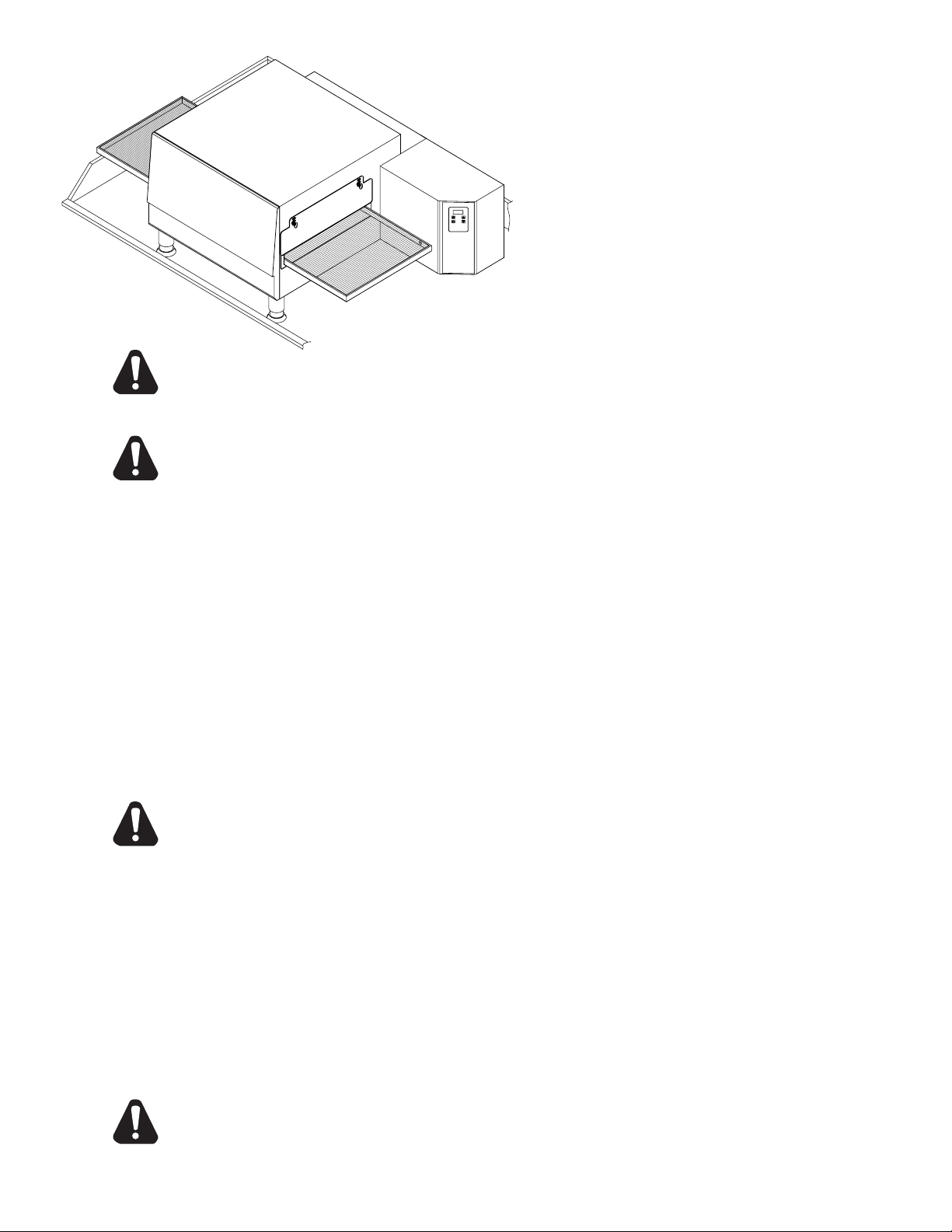
Cet appareil doit être installé sur un table ou
fort position en utilisant les pieds donnés pour
le nettoyage. Minimum, on devrait permettre
24" de l'espace sur l'extrémité du four pour le
déplacement du convoyeur si le four n'est pas
sur un chariot mobile. Permettez l'espace pour
qu'un technicien de service accède à de boîte
de commande et à la couverture de moteur de
ventilateur au-dessus de l'arrière du four si le four
n'est pas mobile.
ATTENTION
N’importe quelle surface que le four est monté dessus devrait avoir un secteur augmenté autour
du périmètre pour empêcher le four de tomber accidentellement le bord. Les dommages ou la
mort sérieux pourraient se produire si le four tombe sur une personne.
ATTENTION
N'importe quel chariot que le four est localisé dessus doit être profond et long pour
fournir une plateforme stable. Un chariot étroit a pu permettre au four de tomber d'et de
dommages la propriété ou de blesser sérieusement des personnes.
VENTILATION
Les codes locaux règnent. Ce sont l’”autorité ayant la juridiction” comme indiqué par le National
Fire Protection Association, Inc. dans le NFPA 96-Latest Edition. Pour davantage d’information
de ventilation voir ci-dessous.
Un capot de ventilation peut être exigé pour enlever la chaleur et des odeurs de cuisine. Le capot
et l’installation de la HVAC doivent rencontrer des codes locaux pour gagner l’approbation par
l’autorité ayant la juridiction. Les conditions peuvent changer dans tout le pays selon l’endroit par
la ville, le comté, et l’état. Obtenez l’information de l’autorité ayant la juridiction pour déterminer
les conditions pour votre installation. Obtenez les copies de l’information et de revue des codes
ou des documents qui seront employés pour inspecter et approuver votre installation. Votre
fournisseur de capot de ventilation et entrepreneur de la HVAC devraient être contactés pour
fournir des conseils.
Empêchez le fl ux d’air par le tunnel à cuire. De l’air ne doit pas être dirigé sur le four avant
ou arrière ou vers le côté du secteur à cuire. Ceci peut causer la cuisine inachevée et la
consommation d’énergie accrue.
ATTENTION
RACCORDEMENT ÉLECTRIQUE
Avant d’établir tous les rapports électriques à cette unité, vérifi ez que l’alimentation d’énergie est
proportionnée pour la tension, l’ampérage, et les conditions de phase indiquées de la plaque de
contrôle. Un diagramme de câblage est inclus sous ce pli.
Une fois installé, cet appareil doit être électriquement fondu et son installation doit être conforme
au Code de Electric de National, au ANSI-NFPA 70, à la dernière version, aux instructions
d’installation du fabricant, et aux codes municipaux locaux applicables de bâtiment. Au Canada,
tous les raccordements électriques sont d’être conformes CSA C22.1 - le Part 1 de Code de
Electrical de Canadian et/ou des codes locaux.
Cet appareil est equpped avec un connecteur de trois-fourche pour votre protection contre
le risque de choc et devrait être branché directement à un réceptacle correct de troisfourche. Ne coupez pas ou n'enlevez pas la troisième fourche de ce connecteur.
ATTENTION
6
Page 32
L’INFORMATION IMPORTANTE DE SÛRETÉ
N’essayez pas d’actionner le four jusqu’à ce que le raccordement du service de service ait
été entièrement inspecté par un technicien autorisé de service ou un technicien de Star. Ce
service est exigé par le Star afi n d’aider l’acheteur dans la mise en train appropriée du four sur
l’emplacement. Veuillez noter les détails spécifi ques sur la garantie et assurez-vous que des
rapports de service sont établis aux services de service appropriés.
La garantie ne s’appliquera pas si le four est commencé vers le haut et actionné avant les
utilités et le four étant inspectés et le contrôle fait par un technicien autorisé de service ou un
technicien de Star.
L’INSTALLATION INEXACTE, L’AJUSTE-MENT, LE CHANGEMENT, LE SERVICE, OU
L’ENTRETIEN PEUVENT CAUSER DES DÉGATS MATÉRIELS, DES DOMMAGES, OU LA
MORT. LISEZ TOUTES LES INSTRUCTIONS COMPLÈTEMENT AVANT D’INSTALLER OU
ENTRETENIR CET ÉQUIPEMENT.
ATTENTION
ATTENTION
Des dégagements minimum doivent être maintenus tous les murs et matériaux combustibles.
Les dégagements minimum pour cette unité devraient être à 0 pouces de l’arrière (les butoirs
arrière fournis doivent être en place) et à 6 pouces des deux côtés. Maintenez le four libre et
dégagé de tout le matériel combustible.
N’obstruez pas de ventilation trous dans les panneaux de commande en tant que ces derniers
fournissent air de refroidissement pour les commandes.
Le four doit être actionné seulement sur le type d’électricité montrés du plat de spécifi cations.
ATTENTION
ATTENTION
L’INFORMATION D’INSTALLATION
LES INSTRUCTIONS D’INST ALLATION CONTENUES CI-dessus SONT POUR L’USAGE DU
PERSONNEL QUALIFIÉ D’INSTALLATION ET DE SERVICE SEULEMENT. L’INSTALLATION
OU LE SERVICE PRÈS AUTRE QUE LE PERSONNEL QUALIFIÉ PEUT AVOIR COMME
CONSÉQUENCE LES DOMMAGES AU FOUR ET/OU AUX DOMMAGES À L’OPÉRATEUR.
Le personnel qualifi é d’installation est des individus, une société, une société, ou une compagnie
que chez la personne ou par un représentant sont engagé dedans, et responsable de:
1. L’installation du câblage électrique du mètre électrique, de la boîte de commande principale
ou de la sortie de service à l’appareil électrique.
Le personnel qualifi é d’installation doit être expérimenté dans un tel travail, au courant de toutes
les précautions priées, et s’est conformé à toutes les conditions de l’état ou des autorités locales
ayant la juridiction.
ENDROIT
Le placement bien projeté et approprié de votre four aura comme conséquence la convenance
d’opérateur à long terme et l’exécution satisfaisante.
Il est essentiel qu’à air proportionnée au four soit maintenue pour fournir un écoulement suffi sant
d’air de ventilation. Suivez ces directives:
1. Placez le four dans un secteur qui est exempt d’ébauches.
2. Maintenez le secteur de four libre et dégagé de tous les combustibles tels que le papier, le
carton, et les liquides infl ammables et les dissolvants.
3. Ne placez pas le four sur une base ou un joint de bord à un mur. Ceci limitera l’écoulement
d’air et empêchera la ventilation appropriée aux turbines. Cette condition doit être corrigée
pour empêcher des dommages permanents au four.
4. Sur tous les modèles, le déclenchement du dispositif thermique de la surcharge de la turbine
indique une température ambiante excessive au fond du four. Cette condition doit être corrigée
pour éviter d’endommager permanent le four.
5
Page 33
INFORMATIONS GÉNÉRALES
Cet équipement est conçu et vendu pour le usage commercial seulement par le personnel
qualifi é et expérimenté dans son opération et est pas vendu pour usage du consommateur
dans et autour de la maison ni pour usage directement par le grand public dans des
endroits de service de traiteur.
En premier lieu, chaque caisse devrait être examinée avant de signer le connaissement pour
rapporter importe quels dommages évidents par le camionneur en transit, et pour expliquer le
nombre approprié de caisses. Se il y a des dommages apparents, des arrangements devraient
être pris pour classer une réclamation contre le porteur. Les règlements de commerce entre Etats
exigent que la réclamation doit être lancée par le destinataire. Des équipements appropriés et
bloqués de stockage devraient être arrangés pour oven(s) au besoin pour le protéger contre
des conditions extérieures ou humides à tout moment avant installation.
-IMPORTANT-
Quand vous faites décharger toutes les caisses, ouvrez les caisses et enlevez toutes les
couvertures en plastique. Inspectez immédiatement pour déceler les dommages cachés. Si
quelque chose semble être endommagé, contactez les personnes appropriées immédiatement
pour classer une réclamation de dommages. Après exécution de cette inspection, fi nissez de
déballer le four. Soyez sûr de enlever tout le matériel de papier de protection et emballage
à partir de unité avant chauffage.
POUR VOTRE SÛRETÉ NE STOCKEZ PAS OU EMPLOYEZ PAS ESSENCE OU AUTRES
VAPEURS ET LIQUIDES INFLAMMABLES À PROXIMITÉ DE CECI OU AUCUN AUTRE
APPAREIL.
ATTENTION
INSTALLATION
Les fours sont équipés pour la tension de puissance indiquée sur la plaque signalétique
montée sur l'arrière de la boîte de commande. Ils fonctionneront sur le courant alternatif (C.A.)
seulement. Une corde est incluse avec un connecteur de la NEMA 6-50. Un réceptacle assorti
avec l’approvisionnement de 50 ampères doit être fourni.
ATTENTION
NE RELIEZ PAS AU COURANT CONTINU (C.C).
L'installation du four électrique se conformer au:
CODE ÉLECTRIQUE NATIONAL ET TOUTES LES CODES ET ORDONNANCES
ÉLECTRIQUES LOCALES ET LES RÈGLES ET LES RÈGLEMENTS DE LOCAL
ELECTRIC COMPANY.
LA RESPONSABILITÉ DE L’ACHETEUR
Il est de la responsabilité de l’acheteur:
1. Pour voir que les services électriques pour le four sont installés sur l’emplacement selon
les caractéristiques du fabricant.
2. Pour décharger, désempaquetez, et installez le four dans son endroit approprié et selon
ce manuel d’opération d’installation.
3. Pour voir que services électriques sont reliés correctement par un installateur qualifi é de
votre choix. Tous tels raccordements doivent être conformes aux conditions applicables
de code.
4. Pour assurer le contrôle d’inspection et d’opération par un technicien autorisé de service.
La garantie devient effi cace lors de la vérifi cation de l’installation appropriée.
4
Page 34

CARACTÉRISTIQUES
UM1833A-208V, UM1833A-240V
Evaluer/Raccordement: 6,400W (6,000 élément) 32/29A @ 208/240V
NEMA 6-50 connecteur avec la corde 6' huile-résistante
Alimentation Électrique: Indépendant 50 Amp 208/240VAC, monophasé, 50/60 Hz service par Four
Poids Approximatif (1833 avec des jambes): Installé - 180 Lbs (81.8 kg), Transporté - 210 Lbs (95.5 kg)
Dimensions: Largeur: 51.2" (130.0 cm) - Four avec des étagères
Profondeur: 30.4" (77.2 cm)
Hauteur: 20.0" (50.8 cm) - Un four avec des jambes
36.0" (91.4 cm) - Deux fours avec des jambes
Les Dégagements Minimums recommandés :
L’arrière de Four pour Emprisonner 0" (0 CM)
Les Extensions de convoyeur pour Emprisonner 6" (15.2 CM)
UM1850A-208V, UM1850A-240V
Evaluer/Raccordement: 6,400W (6,000 élément) 32/29A @ 208/240V
NEMA 6-50 connecteur avec la corde 6' huile-résistante
Alimentation Électrique: Indépendant 50 Amp 208/240VAC, monophasé, 50/60 Hz service par Four
Poids Approximatif (1850 avec des jambes): Installé - 210 Lbs (95.5 kg), Transporté - 240 Lbs (109.1 kg)
Dimensions: Largeur: 50.0" (127.0 cm)
Profondeur: 30.4" (77.2 cm)
Hauteur: 20.0" (50.8 cm) - Un four avec des jambes
36.0" (91.4 cm) - Deux fours avec des jambes
Les Dégagements Minimums recommandés :
L’arrière de Four pour Emprisonner 0" (0 CM)
Les Extensions de convoyeur pour Emprisonner 6" (15.2 CM)
2
Page 35

SYMBOLE DE SÉCURITÉ
CONSERVEZ CE MANUEL POUR RÉFÉRENCE FUTURE
L’utilisation de toute pièce autre que les pièces d’origine STAR dégage le fabricant de toute responsabilité.
Star se réserve le droit de changer les spécifi cations et la conception du produit
sans préavis. Ces changements ne donnent pas le droit à l’acheteur d’obtenir
les changements, améliorations, ajouts ou remplacements correspondants pour
l’équipement acheté préalablement.
Dû aux modifi cations périodiques de dessins, méthodes, procédures, règles
et régulations, les spécifi cations contenues dans ce manuel sont susceptibles
de changer sans préavis. Quoique STAR Manufacturing exerce la bonne foi de
fournir le renseignement correct, STAR n’est pas responsable pour les erreurs
ou les omissions dans le renseignement pourvu ou les conclusions tirées à la
suite de l’utilisation des spécifi cations. En utilisant le renseignement pourvu,
l’utilisateur assume tous les risques en relation avec telle utilisation.
Ces symboles sont utilisés pour souligner à l’utilisateur les
instructions d’utilisation ou d’entretien importantes contenues
dans le manuel qui accompagne l’appareil.
AVIS
ENTRETIEN ET RÉPARATIONS
Contactez votre détaillent local pour les réparations ou l’entretien requis. Assurez-vous d’avoir
le numéro de modèle, le numéro de série, le voltage et la date d’achat pour un service plus
rapide. Entrez l’information requise ci-dessous pour référence rapide.
Agent de service autorisé
N° de modèle
N° de série
Voltage
Date d’achat
Voir la liste pourvue avec l’appareil
Ou
Pour une liste mise à jour voir :
Site web : www.star-mfg.com
Courriel : [email protected]
2
Page 36
®
FOUR de CONVOYEUR
ÉLECTRIQUE
MODÈLES
UM1833A-208V
UM1833A-240V
UM1850A-208V
UM1850A-240V
Instructions
UM1850A
d’installation
et d’opération
2M-Z9844 Rev. B 2/9/07
 Loading...