

Page 1
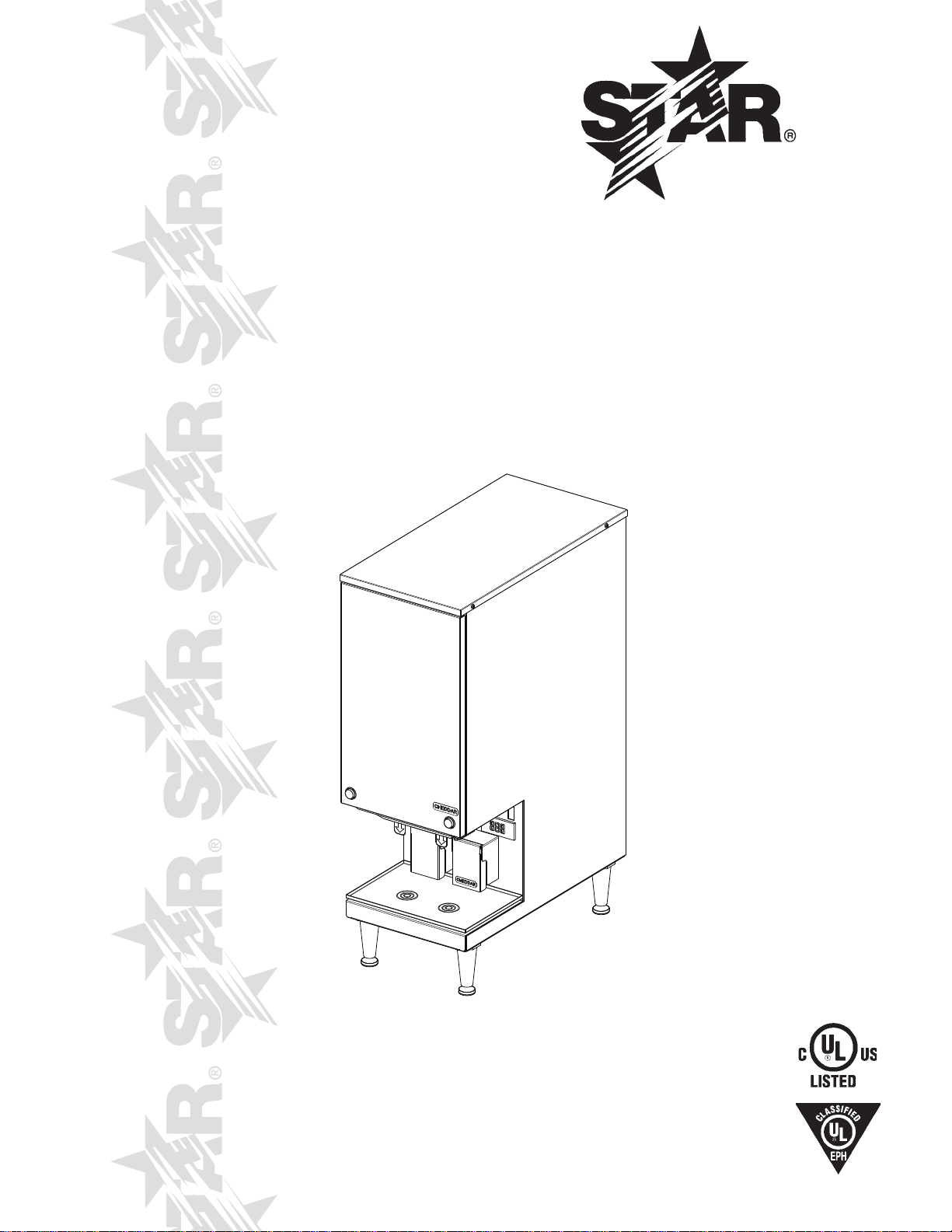
HEATED
PERISTALTIC DISPENSER
MODEL
SPDE1ARB, SPDE2ARB
SPDE1HP
Installation and
Operation
Instructions
2M-Z7537 Rev. L 9/3/2010
SPDE2ARB
1
Page 2

2
These symbols are intended to alert the user to the presence of
important operating and maintenance instructions in the manual
accompanying the appliance.
RETAIN THIS MANUAL FOR FUTURE REFERENCE
NOTICE
Using any part other than genuine Star factory supplied parts relieves the
manufacturer of all liability.
Star reserves the right to change specications and product design without
notice. Such revisions do not entitle the buyer to corresponding changes,
improvements, additions or replacements for previously purchased
equipment.
Due to periodic changes in designs, methods, procedures, policies and
regulations, the specications contained in this sheet are subject to change
without notice. While Star International Holdings Inc., Company exercises
good faith efforts to provide information that is accurate, we are not
responsible for errors or omissions in information provided or conclusions
reached as a result of using the specications. By using the information
provided, the user assumes all risks in connection with such use.
MAINTENANCE AND REPAIRS
Contact your local authorized service agent for service or required maintenance.
Please record the model number, serial number, voltage and purchase date in the area below and have it ready when
you call to ensure a faster service.
SAFETY SYMBOL
Model No.
Serial No.
Voltage
Purchase Date
Business
8:00 am to 4:30 p.m. Central Standard Time
Hours:
Telephone: (800) 264-7827 Local (314) 781-2777
Fax: (800) 396-2677 Local (314) 781-2714
E-mail [email protected]
Website: www.star-mfg.com
Service Help Desk
Authorized Service Agent Listing
Reference the listing provided with the unit
or
for an updated listing go to:
Mailing Address: Star International Holdings Inc., Company
10 Sunnen Drive
St. Louis, MO 63143
U.S.A
2
Page 3

SPECIFICATIONS
SPDE1ARB-120V
Capacity: One 160 ounce pouch
Electrical: 120V, 60 hertz, single phase, 820 Watts, 7 amps
Cord: 6 ft. length
Plug: 120V - NEMA 5-15P
Dimensions: 9-7/16" W x 19-9/16" D x 30-5/16" H (23.97 W x 49.69 D x 77.0 H cm)
Net Weight: 42 lbs. (19.1 kg)
SPDE1ARB-230V
Capacity:
Electrical: 230V, 60 hertz, single phase, 820 Watts, 3.5 amps
Cord: 8 ft. length
Plug: 250V 10 amp NEMA-CEE7-7 Euro
Dimensions: 9-7/16" W x 19-9/16" D x 30-5/16" H (23.97 W x 49.69 D x 77.0 H cm)
Net Weight: 42 lbs. (19.1 kg)
SPDE1HP
Capacity:
Electrical: 120V, 60 hertz, single phase, 820 Watts, 7 amps
Cord: 6 ft. length
Plug: 120V - NEMA 5-15P
Dimensions: 9-7/16" W x 19-9/16" D x 27-5/16" H (23.97 W x 49.69 D x 69.4 H cm)
Net Weight: 42 lbs. (19.1 kg)0V
One 160 ounce pouch
One 160 ounce pouch
SPDE2ARB-120V
Capacity:
Electrical: 120V, 60 hertz, single phase, 1000 Watts, 8.5 amps
Cord: 6 ft. length
Plug: 120V - NEMA 5-15P
Dimensions: 10 29/32" W x 21 15/32" D x 32 1/4" H (27.8 W x 54.5 D x 81.9 H cm)
Net Weight: 60 lbs. (27.2 kg)
SPDE2ARB-230V
Capacity:
Electrical: 230V, 50 hertz, single phase, 1000 Watts, 4.3 amps
Cord: 6 ft. length
Plug: 250V 10 amp NEMA-CEE7-7 Euro
Dimensions: 10 29/32" W x 21 15/32" D x 32 1/4" H (27.8 W x 54.5 D x 81.9 H cm)
Net Weight: 60 lbs. (27.2 kg)
Two 128 ounce pouches
Two 128 ounce pouches
3
Page 4
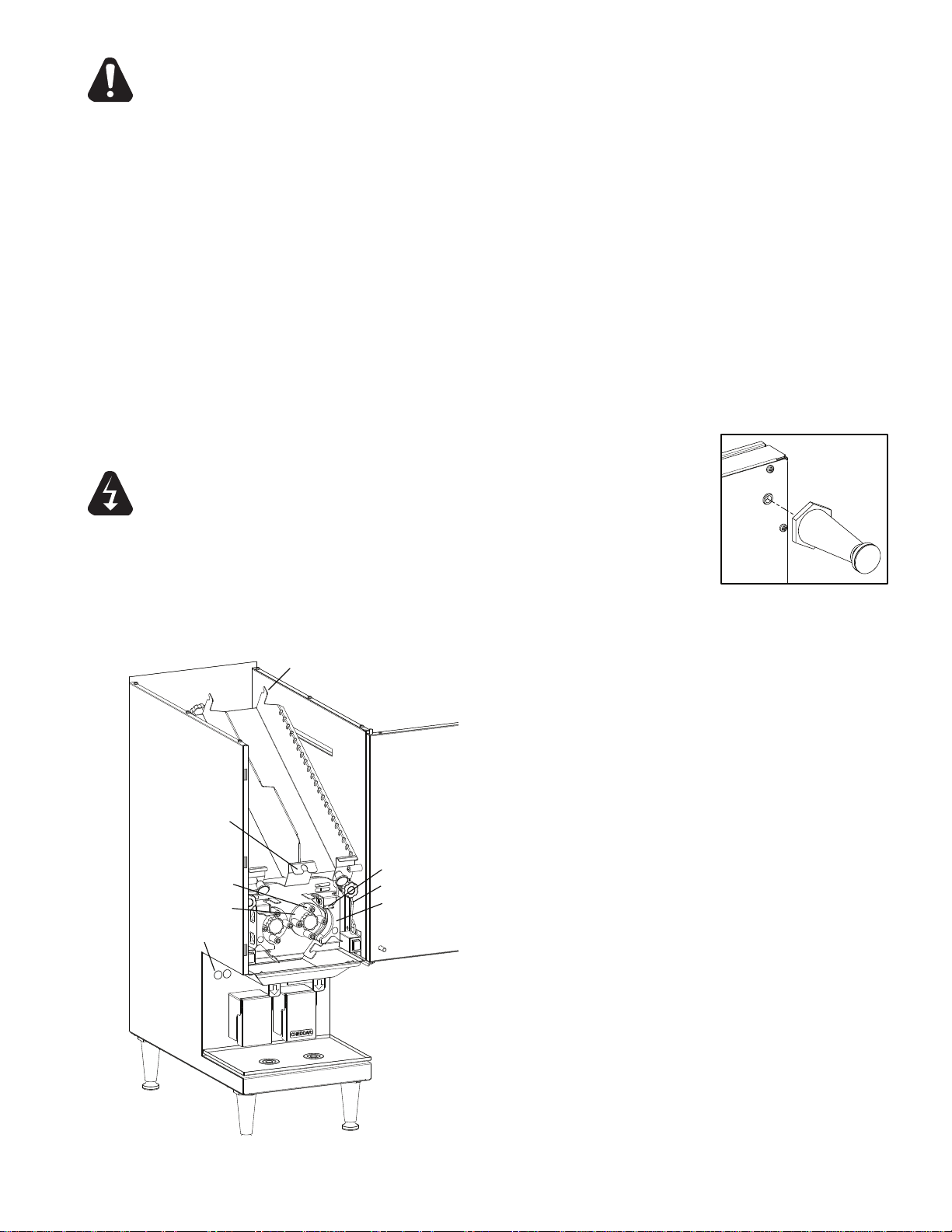
Bag Hook (some models)
Tension Spring
Catch
Pump Block
Rollers
Pump
Head
Tube Changing
Bracket
(SPDE2ARB only)
IL1234
Portion Controls
IL1235
CAUTION
WARNING
This equipment is designed and sold for commercial use only by personnel trained and experienced
in its operation and is not sold for consumer use in and around the home nor for use directly by the
general public in food service locations.
Before using your new equipment, read and understand all the instructions & labels associated with
the unit prior to putting it into operation. Make sure all people associated with its use understand the
units operation & safety before they use the unit.
All shipping containers should be checked for freight damage both visible and concealed. This unit
has been tested and carefully packaged to insure delivery of your unit in perfect condition.
If equipment is received in damaged condition, either apparent or concealed, a claim must be made
with the delivering carrier.
Concealed damage or loss - if damage or loss is not apparent until after equipment is unpacked, a
request for inspection of concealed damage must be made with carrier within
15 days. Be certain to
retain all contents plus external and internal packaging materials for inspection. The carrier will make
an inspection and will supply necessary claim forms.
GENERAL INSTALLATION DATA
This peristaltic dispenser is equipped for the voltage and wattage indicated on the nameplate
mounted on the back of the unit and is designed for use on alternating current (AC) only.
NOTE: The peristaltic dispenser should not be installed without the
legs provided with the machine. The legs screw into the nuts on
the bottom of the dispenser.
DO NOT CONNECT TO DIRECT CURRENT (DC).
GENERAL OPERATING INSTRUCTIONS
The SPDE1 heated dispenser is designed to be used with a 9” x 18”
(22.8 x 45.7cm) poly bag with a 1 inch (2.5cm) outlet tment. The peristaltic
dispenser is designed to be used with 1/4 inch ID (.6cm) to 1/2 inch id.
(1.3cm) tubing with 1/16 inch (.16cm) wall thickness. SPDE2 slightly
smaller.
Loading Product:
1. Turn the dispenser OFF.
2. Unhook the tension spring from the catch.
3. Slide the pump block away from the pump head.
4. The product should be preheated according to the
manufacturer's instructions and should be a minimum
140°F (60°C) before dispensing.
of
5. Insert the new bag into the tray making sure the tment
rests on the block track and route the tube around the
rollers.
SPDE2ARB models have a Tube Changing Bracket,
when loading only one bag, clip the tube of the second
bag in the bracket, to prevent product from leaking.
(NOTE: Make sure tube is not twisted.)
6. Hook the top of the bag on the bag hooks, some
models.
7.
Place the end of the tube in the slot of the bottom
bracket.
8.
Slide the pump block toward the pump head.
9. Hook the tension spring onto the catch.
10. Route the tube through the hole in the tube cover leaving
1/2" of the tube below the cover.
11. Dispense a small amount of product to insure the tube
is seated correctly and the product is owing.
4
Page 5
IL1269
PORTION CONTROL
IL1268
This dispenser is supplied with a portion control timer. This portion control is based on a time setting.
Variations in product temperature and consistency will affect the dispensed amount. To insure a
consistent portion, use product that is at the correct temperature (145°F to 160°).
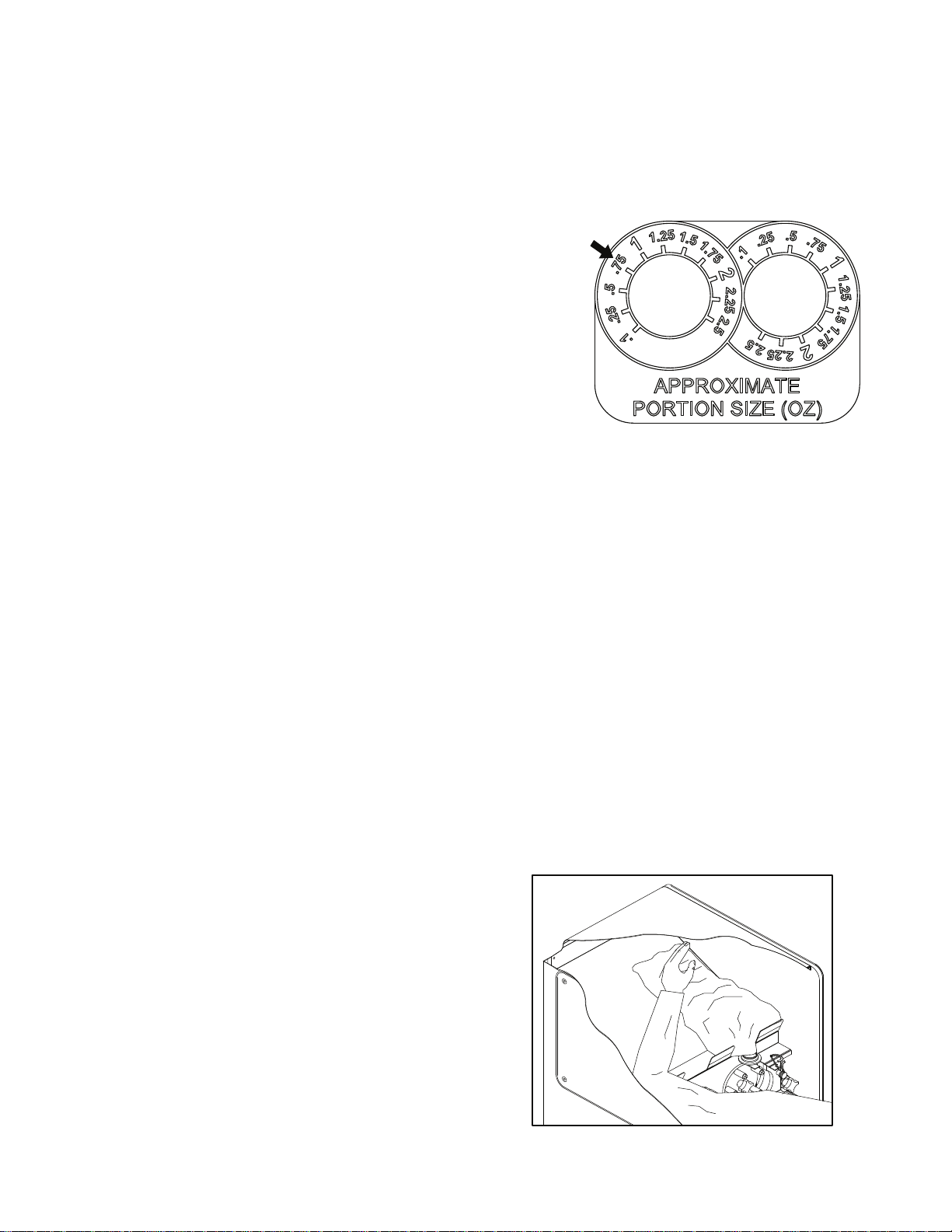
SPDE2 models have a Portion Control Label showing approximate settings for portion size
in oz, see Fig 1. The units are pre-set at the factory for 0.75oz, this is a general guideline,
and following procedures still need to be followed to complete calibration.
To set portion:
1. Load preheated product bag into dispenser.
2. Dispense product until there is a steady ow.
3. Dispense the product into a clean container and measure
the product to verify the dispensed amount.
4.
Using a small screwdriver, remove the round plug covering
the adjustment knob located on the front of the unit below
the tube cover.
5.
Turn the control dial clockwise for more product
and counterclockwise for less product.
6.
Repeat steps 3 and 5 until the desired amount
is reached.
Figure 1, Portion Control Label,
SPDE2 models only.
OPERATION NOTES
The product should be preheated according to the manufacturer's instructions.
The product should be a minimum of 140°F before dispensing.
The digital temperature readout displays the cabinet air temperature and will uctuate during
normal operation. The product temperature should be close to the temperature set point, but
the actual product temperature should be checked periodically to ensure proper operation.
The dispenser will not function correctly if the product is not at the correct temperature.
CHECKING PRODUCT TEMPERATURE
The dispenser should be plugged in and turned on with product in the dispenser for a least 5 hours.
1. Dispense at least 3 inches of product into an insulated cup.
2. Without hesitation, insert the thermometer to the bottom of the cup and stir the product gently with
the stem of the thermometer.
3
. Position the tip of the thermometer in the center of the product mass.
4. The temperature should read between 140°F and 160°F.
The dispenser is designed to operate 24 hours a day. Once the product is placed in the dispenser it
should not be removed until the bag is empty or the holding period of the product has expired.
NOTE:
open the dispenser and pull the
product toward the outlet 3 or 4
times during operation, see Fig 2.
To increase the evacuation,
Figure 2, Pull product down once or
twice during operation.
5
Page 6
CHANGING TEMPERATURE SET-POINT
IL1233
The dispenser is preset at the factory for a temperature of 145°F. If a different temperature is required,
the set point can be changed in a range from 140°F to 160°F. To change the temperature:
1. Press SET. "SP" will appear in the display.
2. Press SET again. The temperature set point will now be displayed.
3. Using the UP or DOWN buttons, set the temperature to the desired value.
4. Press SET again to save the setting.
5. Press the SET and DOWN buttons together to exit the programming mode.
If the pump dies or does not dispense product, check to make sure the tube is routed correctly and the
spring is latched onto the catch.
NOTE: The tube cover must be in place for proper operation.
GENERAL CLEANING INSTRUCTIONS
To clean the peristaltic dispenser:
The stainless steel body is corrosion resistant, but may corrode if not cleaned properly.
The dispenser should be cleaned with a soft cloth with mild soap and water and wiped dry.
Do not use detergents, strong abrasives, or metal scouring pads on the stainless steel panels.
The pump mechanism should not need cleaning during normal use. If product should spill onto the
pump head, it can be removed for easy cleaning. Clean the parts in a solution of mild soap and water
using a soft cloth. Dry parts before reassembling. Be certain to turn the power off to the unit prior to
cleaning the pump assembly.
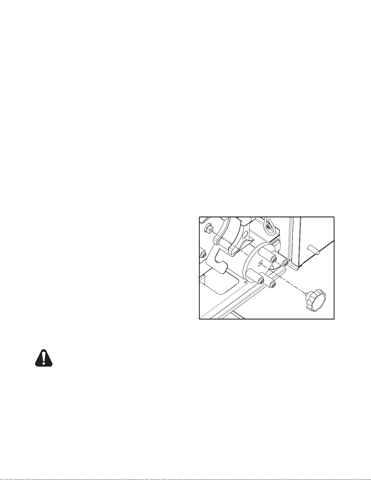
The spring can also be removed for cleaning by removing the knob and retaining washer.
WARNING
To remove and clean the pump head:
1. Turn unit OFF or unplug from the wall
outlet.
2
. Open the door.
3. Remove the bag according to the
instructions.
4.
Unscrew the knob from the pump head.
5. Remove the pump head.
6. Slide the pump block out of the track.
7. If needed the rollers can also be disassembled
for cleaning.
NOTE: When installing the pump head onto the drive shaft, make sure the pump head is fully seated
onto the square end of the drive shaft before installing the knob.
The drive shaft and pump head could be damaged if the pump head is installed incorrectly.
6
Page 7

2M-4497-2 12/06
The foregoing warranty is in lieu of any and all other warranties expressed or implied and constitutes the entire warranty.
FOR ASSISTANCE
Should you need any assistance regarding the Operation or Maintenance of any Star equipment; write, phone, fax or email our Service Department.
In all correspondence mention the Model number and the Serial number of your unit, and the voltage or type of gas you are using.
ALL:
* Pop-Up Toasters
* Butter Dispensers
* Pretzel Merchandisers
(Model 16PD-A Only)
* Pastry Display Cabinets
* Nacho Chip Merchandisers
* Accessories of any kind
* Sneeze Guards
* Pizza Ovens
(Model PO12 Only)
* Heat Lamps
* Pumps-Manual
Visit our Website at: www.star-mfg.com Email: [email protected]
THOROUGHLY INSPECT YOUR UNIT ON ARRIVAL
This unit has been tested for proper operation before leaving our plant to insure delivery of your unit in perfect condition. However, there are instances in
which the unit may be damaged in transit. In the event you discover any type of damage to your product upon receipt, you must immediately contact the
transportation company who delivered the item to you and initiate your claim with same. If this procedure is not followed, it may affect the warranty status of
the unit.
LIMITED EQUIPMENT WARRANTY
All workmanship and material in Star products have a one (1) year limited warranty on parts & labor in the United States and Canada. Such warranty is limited
to the original purchaser only and shall be effective from the date the equipment is placed in service. Star's obligation under this warranty is limited to the repair
of defects without charge, by the factory authorized service agency or one of its sub-agencies. Models that are considered portable (see below) should be taken
to the closest Star service agency, transportation prepaid.
> Star will not assume any responsibility for loss of revenue.
> On all shipments outside the United States and Canada, see International Warranty.
* The warranty period for the JetStar six (6) ounce & Super JetStar eight (8) ounce series popcorn machines is two (2) years.
* The warranty period for the Chrome-Max Griddles is ve (5) years on the griddle surface. See detailed warranty provided with unit.
* The warranty period for Teon/Dura-Tec coatings is one year under normal use and reasonable care. This warranty does not apply if damage occurs to
Teon/Dura-Tec coatings from improper cleaning, maintenance, use of metallic utensils, or abrasive cleaners, abrasive pads, product identiers and
point-of-sale attachments, or any other non-food object tha comes in continuous contact with the roller coating. This warranty does not apply to the
“non-stick” properties of such materials.
> This warranty does not apply to "Special Products" but to regular catalog items only. Star's warranty on "Special Products" is six (6) months on parts
and ninety (90) days on labor.
> This warranty does not apply to any item that is disassembled or tampered with for any purpose other than repair by a Star Authorized Service Center or
the Service Center's sub-agency.
> This warranty does not apply if damage occurs from improper installation, misuse, wrong voltage, wrong gas or operated contrary to the Installation and
Operating instructions.
> This warranty is not valid on Conveyor Ovens unless a "start-up/check-out" has been performed by a Factory Authorized Technician.
PARTS WARRANTY
Parts that are sold to repair out of warranty equipment are warranted for ninety (90) days. The part only is warranted. Labor to replace the part is chargeable to
the customer.
SERVICES NOT COVERED BY WARRANTY
PORTABLE EQUIPMENT
Star will not honor service bills that include travel time and mileage charges for servicing any products considered "Portable" including items listed below.
These products should be taken to the Service Agency for repair:
1. Travel time and mileage rendered beyond the 50 mile radius limit
2. Mileage and travel time on portable equipment (see below)
3. Labor to replace such items that can be replaced easily during a daily cleaning
routine, ie; removable kettles on fryers, knobs, grease drawers on griddles, etc.
4. Installation of equipment
5. Damages due to improper installation
6. Damages from abuse or misuse
7. Operated contrary to the Operating and Installation Instructions
8. Cleaning of equipment
9. Seasoning of griddle plates
10. Voltage conversions
11. Gas conversions
12. Pilot light adjustment
13. Miscellaneous adjustments
14. Thermostat calibration and by-pass adjustment
15. Resetting of circuit breakers or safety controls or reset buttons
16. Replacement of bulbs
17. Replacement of fuses
18. Repair of damage created during transit, delivery, &
installation OR created by acts of God
* The Model 510FD Fryer.
* The Model 526TOA Toaster Oven.
* The Model J4R, 4 oz. Popcorn Machine.
* The Model 518CMA & 526CMA Cheese Melter.
* The Model 12MC & 15MC & 18MCP Hot Food Merchandisers.
* The Model 12NCPW & 15NCPW Nacho Chip/Popcorn Warmer.
* All Hot Dog Equipment except Roller Grills & Drawer Bun Warmers.
* All Nacho Cheese Warmers except Model 11WLA Series Nacho Cheese Warmer.
* All Condiment Dispensers except the Model HPD & SPD Series Dispenser.
* All Specialty Food Warmers except Model 130R, 11RW Series, and 11WSA Series.
* All QCS/RCS Series Toasters except Model QCS3 & RCS3 Series.
7
Page 8
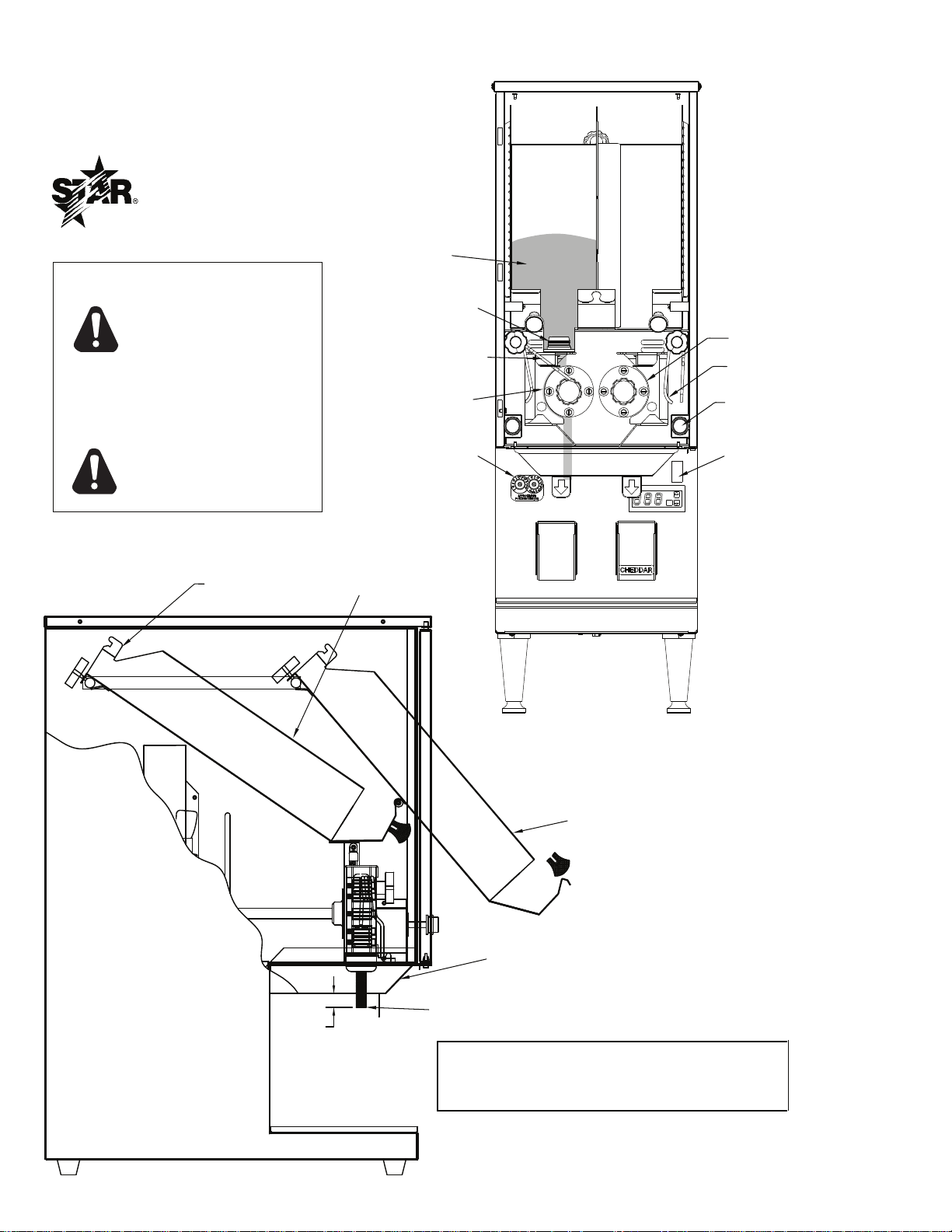
1/2
DISPENSING POSITION
CAUTION: THE BAG HOUSING WILL BE HOT
TO THE TOUCH! WEAR AN OVEN MIT WHILE
LOADING THE MACHINE.
ALWAYS TURN THE
UNIT OFF WHEN
CHANGING A BAG OR
CLEANING THE PUMP
MECHANISM
CAUTION:
DO NOT LIFT THE BAG
HOUSING UNLESS THE
TUBE IS DISENGAGED
FROM THE PUMP HEAD
BAG HOUSING &
LOADING POSITION
BAG HOOK
CUT TUBE HERE
TUBE COVER
PUMP HEAD
POWER SWITCH
SPRING
ENGAGED
FITMENT
SWITCH
PUSH-BUTTON
SPRING
RELEASED
PORTION
CONTROL
BAG
BAG
TUBING
SPDE2ARB PERISTALTIC CHEESE DISPENSER
STAR MANUFACTURING INTL, INC.
P.O. BOX 430129
10 SUNNEN DRIVE
ST. LOUIS, MO 63143
CAUTION:
SK2230 REV. - 1/29/2007
8
Page 9
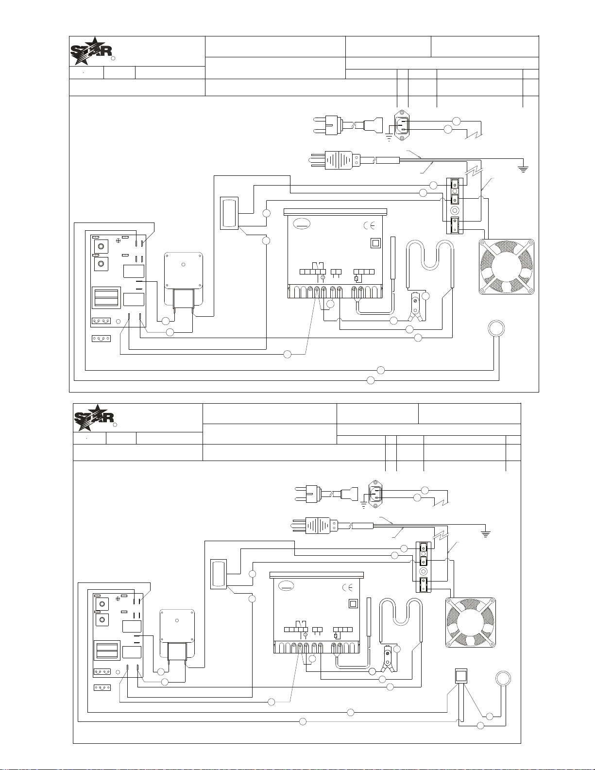
R
MATERIAL
DR.
DATE
FINISH
MODEL NO.
TITLE
PART NO.
TOLERANCES UNLESS OTHERWISE NOTED
FRACTIONS ± 1/64 DECIMALS ± .005
REVISIONS
-
-
SPDE1HP
SK2461
WIRING DIAGRAM SPDE1HP
MH
5-21-10
CK.
LTR DATE DESCRIPTION OF CHANGE DR
THIS DRAWING CONTAINS INFORMATION CONFIDENTIAL TO STAR MFG. INT'L. INC.
NO REPRODUCTION OR DISCLOSURE OF ITS CONTENTS IS PERMITTED.
STAR MANUFACTURING INTERNATIONAL INC.
#10 SUNNEN DRIVE, ST. LOUIS, MO. 63143, USA
-
-
-
-
-
I
16
17
E HEATING ELEMENT
FOR 240V
NEUT
HOT
D
SO-1
SO-2
COM
SW-2
SW-1
7
4
10
12
C
A
6
1
2
5
9
11
G
E
B
A
B TERMINAL BLOCK
D TIMER 0-3 SEC
G LIMIT THERMOSTAT 165°F
J IEC INLET (230V ONLY)
F TEMPERATURE CONTROL WITH PROBE
H FAN
I PUMP SWITCH
A POWER SWITCH
C PUMP MOTOR
FOR 230V
NEMA 5-15P
CEE7-7
FOR 120V
GREEN
B
BLACK
1
19
C
D
15
14
J
H
WHITE
3
8
PZSMS0P1E1
CAREL
R
U
ROHS
1
2 3
4 567
8
9
10
11
NTC
PROBES
L
N
115V
L
F
R
MATERIAL
DR.
DATE
FINISH
MODEL NO.
TITLE
PART NO.
TOLERANCES UNLESS OTHERWISE NOTED
FRACTIONS ± 1/64 DECIMALS ± .005
REVISIONS
-
-
SPDE1ARB
SK2462
WIRING DIAGRAM SPDE1ARB
MH
5-21-10
CK.
LTR DATE DESCRIPTION OF CHANGE DR
THIS DRAWING CONTAINS INFORMATION CONFIDENTIAL TO STAR MFG. INT'L. INC.
NO REPRODUCTION OR DISCLOSURE OF ITS CONTENTS IS PERMITTED.
STAR MANUFACTURING INTERNATIONAL INC.
#10 SUNNEN DRIVE, ST. LOUIS, MO. 63143, USA
-
-
-
-
-
IJ
16
17
18
13
L HEATING ELEMENT
FOR 240V
NEUT
HOT
E
SO-1
SO-2
COM
SW-2
SW-1
7
12
C
A
6
1
2
5
B
A
B TERMINAL BLOCK
E TIMER 0-3 SEC
G LIMIT THERMOSTAT 165°F
K IEC INLET (230V ONLY)
F TEMPERATURE CONTROL WITH PROBE
H FAN
I PUMP SWITCH
J SAFETY SWITCH
A POWER SWITCH
C PUMP MOTOR
FOR 230V
NEMA 5-15P
CEE7-7
FOR 120V
GREEN
B
BLACK
1
19
C
D
15
14
K
H
WHITE
3
4
11
G
L
10
9
G
8
PZSMS0P1E1
CAREL
R
U
ROHS
1
2 3
4 567
8
9
10
11
NTC
PROBES
L
N
115V
L
F
9
Page 10
R
MATERIAL
DR.
DATE
FINISH
MODEL NO.
TITLE
PART NO.
TOLERANCES UNLESS OTHERWISE NOTED
FRACTIONS ± 1/64 DECIMALS ± .005
REVISIONS
-
-
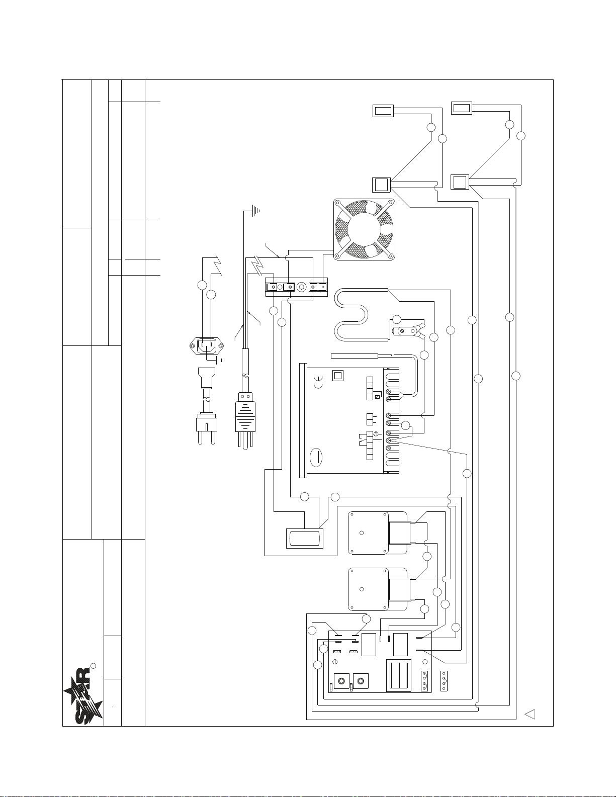
SPDE2ARB
SK2463
WIRING DIAGRAM
MH
5-21-10
CK.
LTR DATE DESCRIPTION OF CHANGE DR
THIS DRAWING CONTAINS INFORMATION CONFIDENTIAL TO STAR MFG. INT'L. INC.
NO REPRODUCTION OR DISCLOSURE OF ITS CONTENTS IS PERMITTED.
STAR MANUFACTURING INTERNATIONAL INC.
#10 SUNNEN DRIVE, ST. LOUIS, MO. 63143, USA
-
-
-
-
-
1
2
GREEN
BLACK
14
15
FOR 230V
FOR 120V
A
B
C
D
3
5
6
19
WHITE
SW-2
FOR 240V
HOT
NEUT
SO-1
SO-2
SW-1
COM
7
24
12
CEE7-7
NEMA 5-15P
A POWER SWITCH
B TERMINAL BLOCK
C LEFT PUMP MOTOR
D RIGHT PUMP MOTOR
E TIMER 0-15 SEC
F TEMPERATURE CONTROL W/PROBE
G LIMIT THERMOSTAT 165°F
H FAN
I1 LEFT PUMP SWITCH
J1 LEFT SAFETY SWITCH *
K IEC INLET (230V ONLY)
A
B
C
E
H
K
L HEATING ELEMENT
1
I1J1
16
17
I2J2
20
21
23
22
13
18
25
D
I2 RIGHT PUMP SWITCH
J2 RIGHT SAFETY SWITCH *
* NOTE: LEFT AND RIGHT SIDE IS WHEN VIEWING DISPENSER FROM THE FRONT (AS IF USING THE UNIT).
13
18
22
23
2
B
4
10
9
11
G
L
8
PZSMS0P1E1
CAREL
R
U
ROHS
1
2 3
4 5
6
7
8
9
10
11
NTC
PROBES
L
N
115V
L
F
10
2M-Z7537 SPDE Heated Peristaltic Dispenser
Page 11
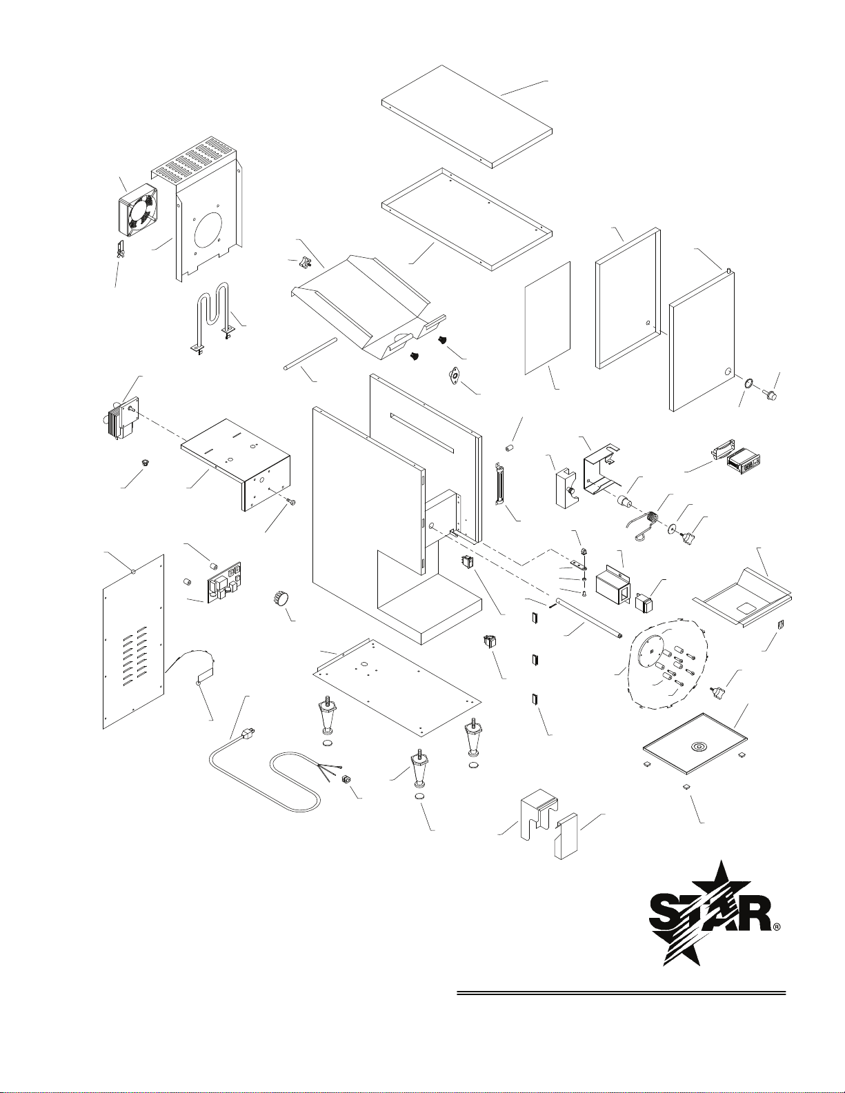
MODELS:
SPDE1ARB, SPDE1HP
SPDE2ARB
STAR MANUFACTURING INTERNATIONAL, INC.
SK2071 REV D
1-10-07
1
18
21
20
8
11
32
41
33
29
2
17
16
4
5
6
27
10
37
39
55
59
40
13
54
42
47
34
26
25
3
48
35
36
49
56
7
9
14
15
22
23
28
30
31
43
44
45
46
50
51
52
53
38
12
NAMEPLATE
24
57
25
19
58
2M-Z7537 SPDE Heated Peristaltic Dispenser
11
Page 12
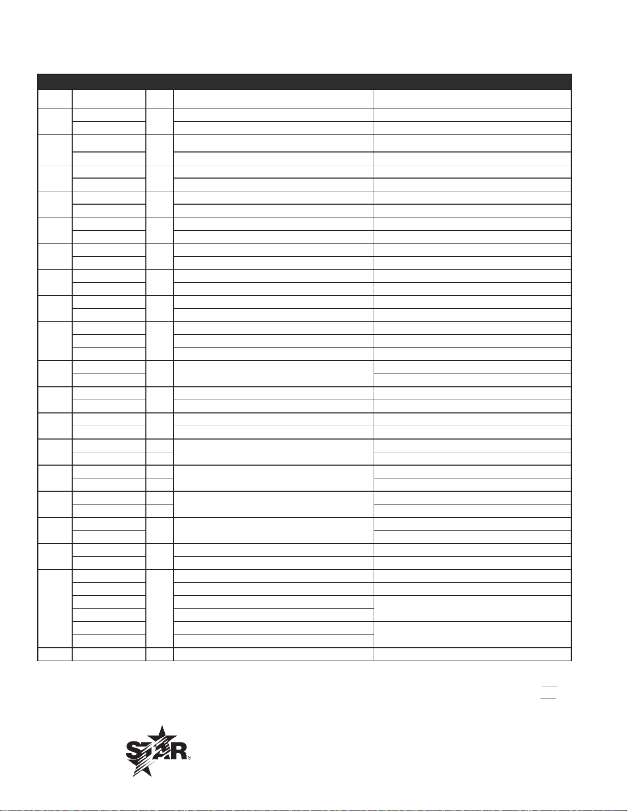
PARTS LIST September 9, 2010, Rev. L
HEATED PERISTALTIC DISPENSER, SPDE1HP, SPDE1ARB, SPDE2ARB
Fig No Part No Qty Description Application
M2-Z5592
1
M2-Z9689 BACK SPDE2ARB
M2-PD1018
2
M2-PD2033 ASY, FAN WALL SPDE2ARB
M2-Z3595
3
M2-Z9684 LINER, DOOR SPDE2ARB
M2-Z2865
4
M2-Z9687 TOP SPDE2ARB
M2-Z2866
5
M2-Z9688 LINER, TOP SPDE2ARB
M2-22097
6
M2-PD2039 ASY, DOOR STUD SPDE2ARB
M2-Z7532
7
M2-Z9690 WALL, MOTOR SPDE2ARB
M2-22073
8
M2-PD2034 ASSEMBLY, BAG HSG-WELD SPDE2ARB
M2-PD2006
9
M2-PD2036 ASY, TRACK - LEFT SPDE2ARB
M2-PD2037 ASY, TRACK - RIGHT SPDE2ARB
M2-PD1012
10
M2-PD2045 SPDE2ARB
M2-Z2889
11
M2-Z9692 TRAY, DRIP SPDE2ARB
M2-22041
12
M2-PD2038 ASSEMBLY, TUBE COVER SPDE2ARB
M2-Z2703 1
13
M2-Z9691 2 SPDE2ARB
M2-Z5596 1
14
M2-Z10176 2 SPDE2ARB
M2-PD1013 1
15
M2-PD2043 2 SPDE2ARB
2A-Z2999
16
2A-Z9797 SPDE2ARB
2N-Z4603
17
2N-Z5044 ELEMENT 230V/650W SPDE1ARB-230V, SPDE2ARB-230V
2U-Z11917
PS-Z10009 MOTOR CCW 165 RPM 120V, KIT SPDE1ARB, SPDE1HP, manuf. Before 10/2006
2U-Z11921 MOTOR CCW 230 RPM 120V
18
2U-Z11922 MOTOR CW 230 RPM 120V
2U-Z13716 MOTOR CCW 230 RPM 230V
2U-Z13717 MOTOR CW 230 RPM 230V
19 2C-1508 4 per SCREW 10-32X3/4” STL RHN, DRIVE MOTOR used with 2U-Z9696, 2U-Z10040
BACK SPDE1ARB, SPDE1HP
1
ASSEMBLY FAN WALL SPDE1ARB, SPDE1HP
1
DOOR LINER SPDE1ARB, SPDE1HP
1
TOP CSD-1 SPDE1ARB, SPDE1HP
1
LINER TOP-CSD-1 SPDE1ARB, SPDE1HP
1
DOOR STUD ASSEMBLY SPDE1ARB, SPDE1HP
1
WALL-MOTOR SPDE1ARB, SPDE1HP
1
BAG HOUSING WELD ASSEMBLY SPDE1ARB, SPDE1HP
1
LEFT BLOCK TRACK ASSEMBLY SPDE1ARB, SPDE1HP
1
1 ASSEMBLY BOTTOM
DRIP TRAY CSD-1N SPDE1ARB, SPDE1HP
1
TUBE COVER ASSEMBLY SPDE1ARB, SPDE1HP
1
COVER-SWITCH
PADDLE BODY
ASSEMBLY PADDLE
1 ROD
ELEMENT 120V/650W
1
MOTOR-CCW 165 RPM 120V SPDE1ARB, SPDE1HP, manuf. After 10/2006
1
SPDE1ARB, SPDE1HP
SPDE1ARB, SPDE1HP
SPDE1ARB
SPDE1ARB
SPDE1ARB, SPDE1HP
SPDE2ARB
SPDE2ARB-230V
2M-Z7537 SPDE Heated Peristaltic Dispenser
IMPORTANT: WHEN ORDERING, SPECIFY VOLTAGE OR TYPE GAS DESIRED PAGE 1
INCLUDE MODEL AND SERIAL NUMBER OF 3
Some items are included for illustrative purposes only and in certain instances may not be available.
Star International Holding Inc. Company
12
Page 13
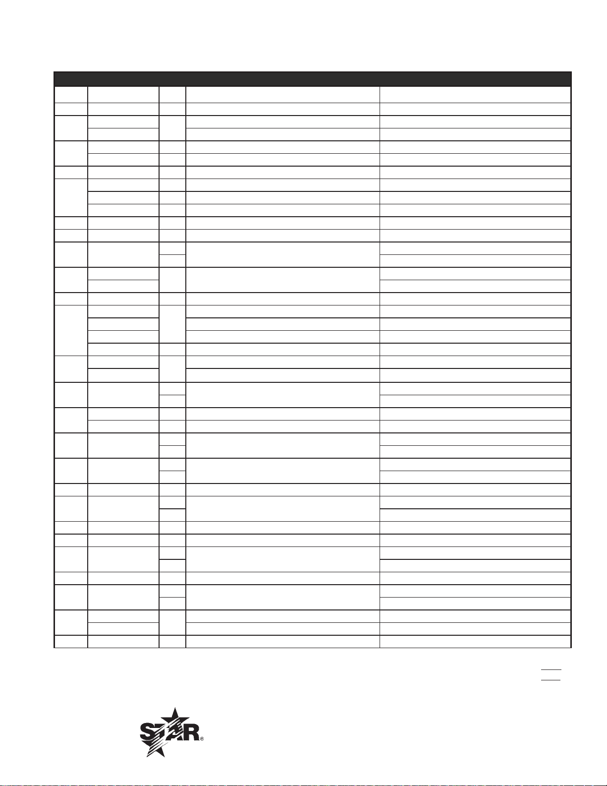
PARTS LIST September 9, 2010, Rev. L
HEATED PERISTALTIC DISPENSER, SPDE1HP, SPDE1ARB, SPDE2ARB
Fig No Part No Qty Description Application
20 2K-7889 1 BUSHING HEYCO SR-11-2
A3-ST3006
21
2E-Z0512 CORDSET, EUR 10A SPDE1ARB-230V, SPDE2ARB-230V
2U-Z4600 1 FAN A/C 110CFM 120V
22
2U-Z5041 1 FAN A/C 110CFM 230V SPDE1ARB-230V, SPDE2ARB-230V
23 2T-Z4666 1 THERMOSTAT 165F
M2-Z11877 1 CONTROL - SET TO 150°F SPDE1ARB,
24
2E-Z7235 1 CONTROL W/SENSOR 230V (includes probe) SPDE2ARB-230V
M2-Z10046 1 CONTROLLER, PROGRAMMED SPDE2ARB
25 2R-Z6774 2 KNOB, DAVIES 4200 10-24 x 1/4
26 2R-Z0872 2 KNOB, DAVIES #3004-S
27 2P-9615
2M-Z3607
28
2M-Z10311 SPDE2ARB
30 2A-Z3429 2 SPACER-NYLON .175X.375X.5
M2-Z10302
M2-Z10131 TIMER PROGRAMMED SPDE1ARB, SPDE2ARB
31
M2-Z10303 TIMER PROGRAMMED 230V SPDE1ARB-230V
M2-Z13719 1 TIMER PROGRAMMED 230V SPDE2ARB-230V
2E-Z0091
32
PS-PD2046 HPD SWITCH SERVICE KIT, LIGHTED SWT REPL BEFORE 12/2009
33 2C-Z11912
2P-Z1735 1 PLUG CAP 3/4 SPDE1HP, SPDE1ARB
34
2P-09-WB-0003 2 PLUG CAP SPDE2ARB
35 2A-Z1621
36 2C-Z1620
37 2R-Z2883 3 MAG CATCH SOUTHCO 300
38 2M-Z1688
39 2T-Z0613 1 THERMOMETER-SPIRIT
40 2I-Z1894 1 HINGE-INSERT
41 2A-Z4595
42 2A-Z2233 1 SLEEVE-HINGE
2M-Z7537 SPDE Heated Peristaltic Dispenser
43 2E-Z1622
2R-Y5092
44
2R-Z5846 FOOT 1” SPDE1HP
45 2I-Z1914 4 RUBBER PAD SPDE1ARB, SPDE2ARB
CORDSET ASSEMBLY
1
1
BEARING-SELF ALIGN
2 SPDE2ARB
1 LABEL-OPERATING
TIMER 0-15 SECONDS SPDE1HP
1
SWITCH-ON/OFF NON-LIGHTED
1
1
HAIR PIN .091 DIA. X 1.625
2 SPDE2ARB
5
ROLLER #10X1/2X1 NYLON
8 SPDE2ARB
5
SHOULDER SCREW 8-32X1/4
8 SPDE2ARB
1
GRAPHIC ARROW
2 SPDE2ARB
1
DRIVE SHAFT
2 SPDE2ARB
1
SWITCH, MOMENTARY
2 SPDE2ARB
FOOT BLACK PLASTIC 4” SPDE1ARB, SPDE2ARB
4
SPDE1ARB
SPDE1HP, SPDE1ARB
SPDE1HP, SPDE1ARB
SPDE1HP, SPDE1ARB
SPDE1HP, SPDE1ARB
SPDE1HP, SPDE1ARB
IMPORTANT: WHEN ORDERING, SPECIFY VOLTAGE OR TYPE GAS DESIRED PAGE 2
INCLUDE MODEL AND SERIAL NUMBER OF 3
Some items are included for illustrative purposes only and in certain instances may not be available.
Star International Holding Inc. Company
13
Page 14
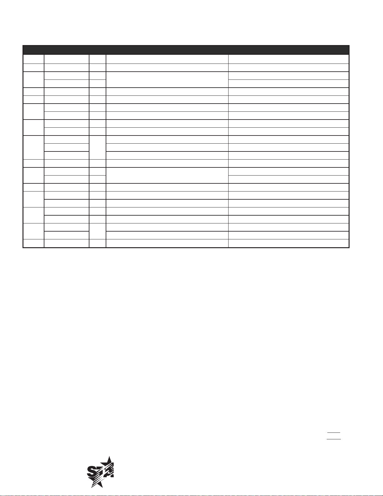
PARTS LIST September 9, 2010, Rev. L
HEATED PERISTALTIC DISPENSER, SPDE1HP, SPDE1ARB, SPDE2ARB
Fig No Part No Qty Description Application
46 2A-H7804 4 BUMP ON 1/4” X 1/2 SQ.
2R-Z2848 1
47
2R-Z2848 2 SPDE2ARB
48 2K-Z0714 1 SHORTY-BUSHING
49 2A-Z5564 1 PUMP HEAD SPDE1ARB, SPDE1HP
M2-22049 1 ASSEMBLY BLOCK RIGHT SPDE1ARB, SPDE1HP
50
M2-PD2040 2 ASSEMBLY - BLOCK SPDE2ARB
2A-Z1616 1 BUSHING SPDE1ARB, SPDE1HP
51
2A-Z9697 2 BUSHING, SPRING SPDE2ARB
2P-Z4598
52
2P-Z10267 SPRING, LH SPDE2ARB
2P-Z10268 SPRING, RH SPDE2ARB
53 2C-Z1689 1 WASHER 1.25 OD x 9/32 ID SPDE1ARB, SPDE1HP
2E-Z2680 1
54
2E-Z9698 2 SPDE2ARB
55 M2-Z3601 1 HINGE BRACKET
2A-Z5564 1 PUMP HEAD ASSEMBLY SPDE1ARB, SPDE1HP
56
2A-Z9681 2 ASY, PUMP HEAD - COMPLETE SPDE2ARB
2R-Z6774 1 KNOB, DAVIES 4200 10-24 x 1/4
57
2R-Z9686 2 KNOB, DAVIES 2860AP 1/4-20 SPDE2ARB
2A-Z3429
58
2A-Z1621 ROLLER #10X1/2X1 NYLON SPDE2ARB
59 2C-2853 1 SCREW #8X5/8 A THP STL NP
PUSH BUTTON (Dispensing)
SPRING LEFT HPD SPDE1ARB, SPDE1HP
1
SWITCH-PUSH BUTTON
SPACER-NYLON .175X.375X.5 SPDE1ARB, SPDE1HP
2
SPDE1ARB, SPDE1HP
IMPORTANT: WHEN ORDERING, SPECIFY VOLTAGE OR TYPE GAS DESIRED PAGE 3
INCLUDE MODEL AND SERIAL NUMBER OF 3
Some items are included for illustrative purposes only and in certain instances may not be available.
Star International Holding Inc. Company
14
2M-Z7537 SPDE Heated Peristaltic Dispenser
Page 15

2M-Z7537 SPDE Heated Peristaltic Dispenser
15
Page 16

STAR INTERNATIONAL HOLDINGS INC. COMPANY
Star - Holman - Lang - Wells - Bloomeld - Toastmaster
10 Sunnen Drive, St. Louis, MO 63143 U.S.A.
(314) 781-2777
www.star-mfg.com
16
 Loading...