

Star SP712R series, SP742R series Hardware Manual

DOT PRINTER
SP712R / 742R
(Paper Rewinder Model)
SERIES
Hardware Manual

Federal Communications Commission
Radio Frequency Interference
Statement
This device complies with Part 15 of the FCC Rules. Operation is subject to the following two conditions: (1) This
device may not cause harmful interference, and (2) this device must accept any interference received, including
interference that may cause undesired operation.
NOTE: This equipment has been tested and found to comply with the limits for a Class A digital device, pursuant
to Part 15 of the FCC Rules. These limits are designed to provide reasonable protection against harmful interference
when the equipment is operated in a commercial environment. This equipment generates, uses and can radiate
radio frequency energy and, if not installed and used in accordance with the instruction manual, may cause harmful
interference to radio communications. Operation of this equipment in a residential area is likely to cause harmful
interference in which case the user will be required to correct the interference at his own expense.
This statement will be applied only for the printers marketed in U.S.A.
FCC WARNING
Changes or modications not expressly approved by the party responsible for compliance could void the user’s
authority to operate the equipment.
For compliance with the Federal Noise Interference Standard, this equipment requires a shielded cable.
For RF interference suppression, if a ferrite core is provided with this device, afx it to the interface cable
Statement of
The Canadian Department of Communications
Radio Interference Regulationst
This Class A digital apparatus complies with Canadian ICES-003.
Cet appareil numérique de la classe A est conforme à la norme NMB-003 du Canada.
The above statement applies only to printers marketed in Canada.
Trademark acknowledgments
SP700: Star Micronics Co., Ltd.
Notice
• All rights reserved. Reproduction of any part of this manual in any form whatsoever, without STAR’s
express permission is forbidden.
• The contents of this manual are subject to change without notice.
• All efforts have been made to ensure the accuracy of the contents of this manual at the time of going to
press. However, should any errors be detected, STAR would greatly appreciate being informed of them.
• The above notwithstanding, STAR can assume no responsibility for any errors in this manual.
©
Copyright2007-2010StarMicronicsCo.,Ltd.

TABLE OF CONTENTS
1. Outline .......................................................................................................................................................1
2. Unpacking and Installation .....................................................................................................................2
2-1. Unpacking ....................................................................................................................................2
2-2. Choosing a place for the printer ...................................................................................................3
2-3. Handling Care ..............................................................................................................................4
2-4. Maintenance .................................................................................................................................4
3. Parts Identication and Nomenclature ..................................................................................................5
4. Setup ..........................................................................................................................................................6
4-1. Connecting the Cable to the PC ...................................................................................................6
4-2. Connecting the Cable to the Printer .............................................................................................7
4-3. Installing the Printer Software ...................................................................................................10
4-4. Connecting to a Peripheral Unit ................................................................................................. 11
4-5. Connecting the Power Cord .......................................................................................................12
4-6. Turning Power On ......................................................................................................................13
4-7. Installing the Cable ....................................................................................................................14
4-8. Switch Blind Installation ............................................................................................................14
5. Loading the Ribbon Cartridge and Paper ...........................................................................................15
5-1. Loading the Ribbon Cartridge ...................................................................................................15
5-2. Loading the paper roll ................................................................................................................16
5-3. Installing the Roll Paper Guide ..................................................................................................19
6. Control Panel and Other Functions .....................................................................................................22
6-1. Control Panel .............................................................................................................................22
6-2. Basic Indicators ..........................................................................................................................22
6-3. Errors ..........................................................................................................................................23
6-4. Adjustment Mode .......................................................................................................................25
7. Preventing and Clearing Paper Jams ...................................................................................................31
7-1. Preventing Paper Jams ...............................................................................................................31
7-2. Removing Paper Jam .................................................................................................................31
7-3. Releasing a Locked Cutter (Auto Cutter Mode only) ................................................................32
8. Peripheral Unit Drive Circuit ...............................................................................................................34
9. General Specications ...........................................................................................................................36
9-1. General Specications ...............................................................................................................36
9-2. Power Supply Specications ......................................................................................................38
10. Dip Switch Setting ................................................................................................................................39
10-1. RS-232C Interface Model ..........................................................................................................41
10-2. Parallel Interface Model .............................................................................................................42
10-3. USB Interface Model .................................................................................................................42
10-4. Ethernet Interface Model ...........................................................................................................42
10-5. Wireless LAN Interface Model ..................................................................................................43
11. RS-232C Serial Interface .....................................................................................................................46
11-1. Interface Specications ..............................................................................................................46
11-2. Pins and Signal Names ...............................................................................................................47
11-3. Interface Connections ................................................................................................................48
12. Parallel Interface ..................................................................................................................................49
12-1. Table of Connection Signals for Each Mode .............................................................................49

13. USB, Ethernet and Wireless LAN Interface ......................................................................................51
13-1. USB Interface Specications .....................................................................................................51
13-2. Ethernet Interface Specications................................................................................................51
13-3. Wireless LAN Interface Specications ......................................................................................51
14. Memory Switch Settings ......................................................................................................................52
15. Release History .....................................................................................................................................53
Please access the following URL
http://www.star-m.jp/eng/dl/dl02.htm
for the latest revision of the manual.

1. Outline
The SP700 Series Serial Impact Dot Matrix Printer is designed for use with electronic instruments such as POS, banking equipment, computer peripheral equipment, etc.
SP7 1 2 M D R
Color
None : Standard color (off-white)
GRY : Gray
Rewinder
None : Without rewinder (Standard)
R : With rewinder
Interface
D : Serial interface (RS-232C)
C : Parallel interface
U : USB
E : Ethernet
W : Wireless LAN
Paper feed
M : Friction paper feed method
Mechanism
2 : Reserved
Printer type
1 : Tear bar type
4 : Auto cutter equipped type
SP700 series printer
– 1 –
2. Unpacking and Installation
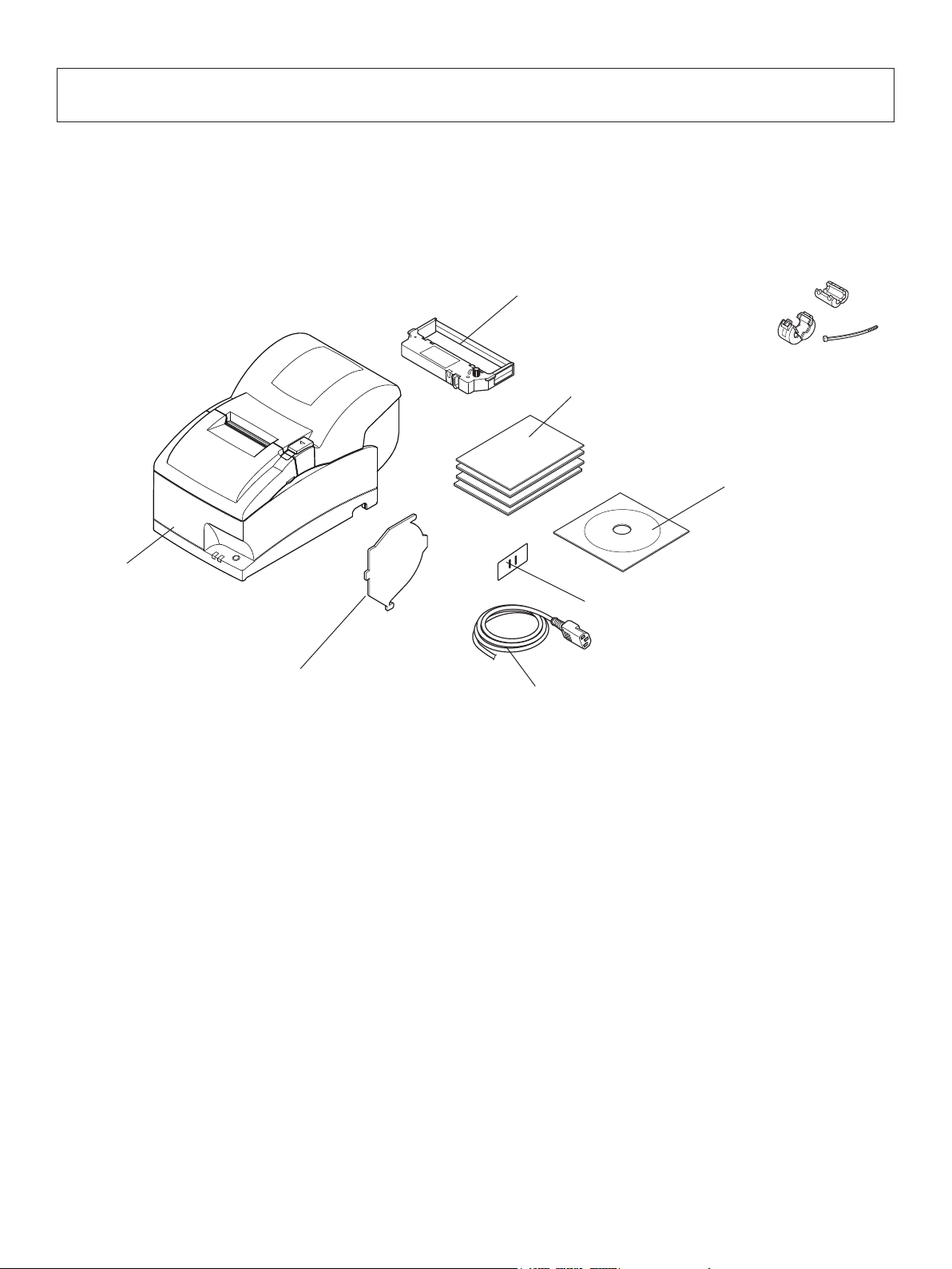
2-1. Unpacking
After unpacking the unit, check that all the necessary accessories are included in the package.
Ribbon cartridge
Note
Setup sheets
CD-ROM
Printer
Switch blind
Roll paper guide
Power cord
Note: The ferrite core and fastener provided with your
printer depend on your printer conguration.
Fig. 1-1 Unpacking
If anything is missing, contact the dealer where you bought the printer and ask them to supply
the missing part. Note that it is a good idea to keep the original box and all the packing materials
just in case you need to pack the printer up again and send it somewhere at a later date.
– 2 –

2-2. Choosing a place for the printer
Before actually unpacking the printer, you should take a few minutes to think about where
you plan to use it. Remember the following points when doing this.
P Choose a rm, level surface where the printer will not be exposed to vibration.
P The power outlet you plan to connect to for power should be nearby and unobstructed.
P Make sure that the printer is close enough to your host computer for you to connect
the two.
P Make sure that the printer is not exposed to direct sunlight.
P Make sure that the printer is well away from heaters and other sources of extreme heat.
P Make sure that the surrounding area is clean, dry, and free of dust.
P Make sure that the printer is connected to a reliable power outlet. It should not be on
the same electric circuit as copiers, refrigerators, or other appliances that cause power
spikes.
P Make sure that the room where you are using the printer is not too humid.
P This device employs a DC motor and switches that have an electrical contact point.
Avoid using the device in environments where silicon gas can become volatile.
PWhen disposing of the printer, obey local regulations.
WARNING
P Shut down your equipment immediately if it produces smoke, a strange odor, or unu-
sual noise. Immediately unplug the equipment and contact your dealer for advice.
P Never attempt to repair this product yourself. Improper repair work can be dangerous.
P Never disassemble or modify this product. Tampering with this product may result in
injury, re, or electric shock.
– 3 –

2-3. Handling Care
1. Be careful not to drop paper clips, pins or other foreign matter into the unit as these cause
the printer to malfunction.
2. Do not attempt to print when either paper or ribbon cartridge is not located in the printer,
otherwise the print head can be damaged.
3. Do not open the cover while printing.
4. Do not touch the print head immediately after printing as it gets very hot.
5. Use only roll paper that is not glued to the core.
6. When the paper end mark appears on the paper, replace the roll paper before it runs out.
2-4. Maintenance
Essentially, your printer is a robust piece of equipment, but should be treated with a modicum
of care in order to avoid malfunctions. For example:
1. Keep your printer in a “comfortable” environment. Roughly speaking, if you feel comfortable, then the environment is suitable for your printer.
2. Do not subject the printer to physical shocks or excessive vibration.
3. Avoid over-dusty environments. Dust is the enemy of all precision mechanical devices.
4. To clean the exterior of the printer, use a cloth barely dampened with either water with a
little detergent or a little alcohol, but do not allow any liquid to fall inside the printer.
5. The interior of the printer may be cleaned with a small cleaner or a compressed-air aerosol
(sold for this purpose). When performing this operation, be sure not to bend or damage any
cable connections or electronic components.
– 4 –
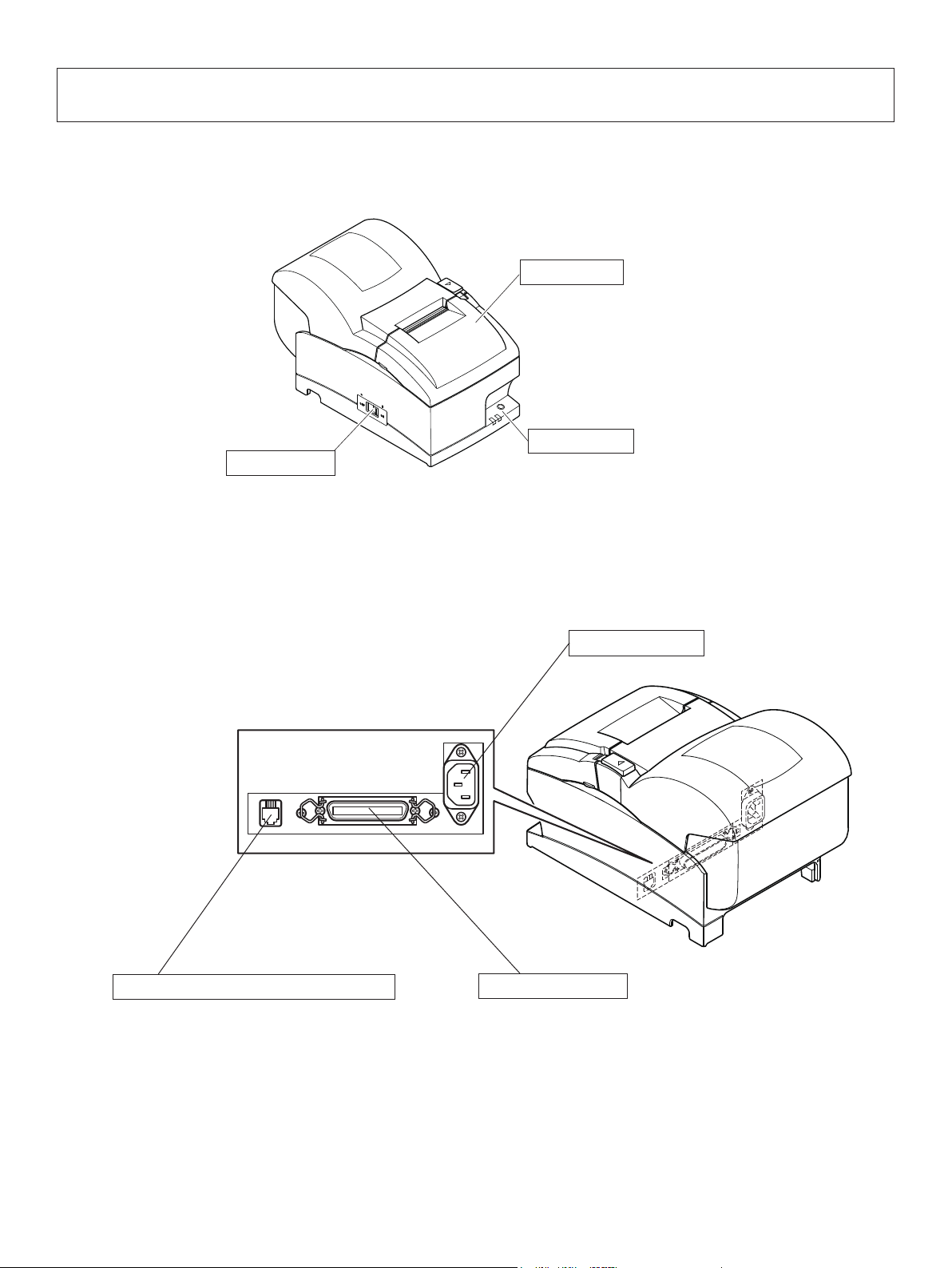
3. Parts Identication and Nomenclature
Printer cover
Protects the printer from dust and reduces noise.
Do not open the cover while printing.
Control panel
Power switch
Turns printer power
on and off.
Features one control switch and two indicators
to indicate printer status.
Peripheral unit drive circuit connector
Connects to peripheral units such as cash
drawers, etc.
Do not connect this to a telephone.
Power connector
For connection of the power cord.
Interface connector
Connects the printer with host
computer.
– 5 –
4. Setup
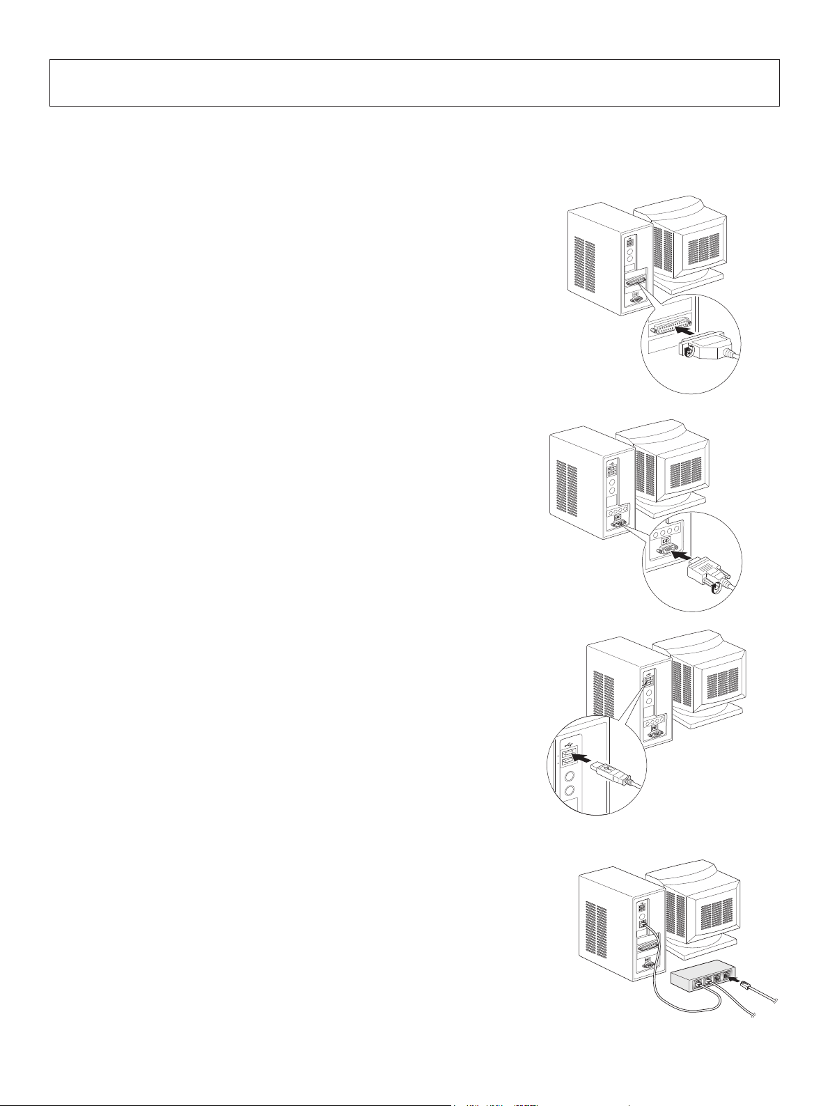
4-1. Connecting the Cable to the PC
4-1-1. Parallel Interface Cable
Connect the parallel interface cable to a parallel port
of your PC.
4-1-2. RC-232 Interface Cable
Connect the RC-232 interface cable to a RS-232 port
of your PC.
4-1-3. USB Interface Cable
Connect the USB interface cable to a USB port of
your PC.
4-1-4. Ethernet Interface cable
Connect the ethernet interface cable to a ethernet port
of your PC.
– 6 –
4-2. Connecting the Cable to the Printer
Note that the interface cable is not provided. Please use a cable that meets specications.
CAUTION
Before connecting/disconnecting the interface cable, make sure that power to the printer and
all the devices connected to the printer is turned off. Also make sure the power cable plug is
disconnected from the AC outlet.
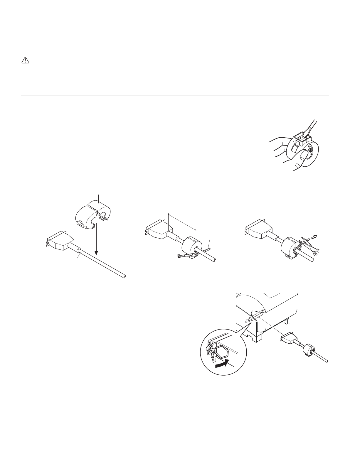
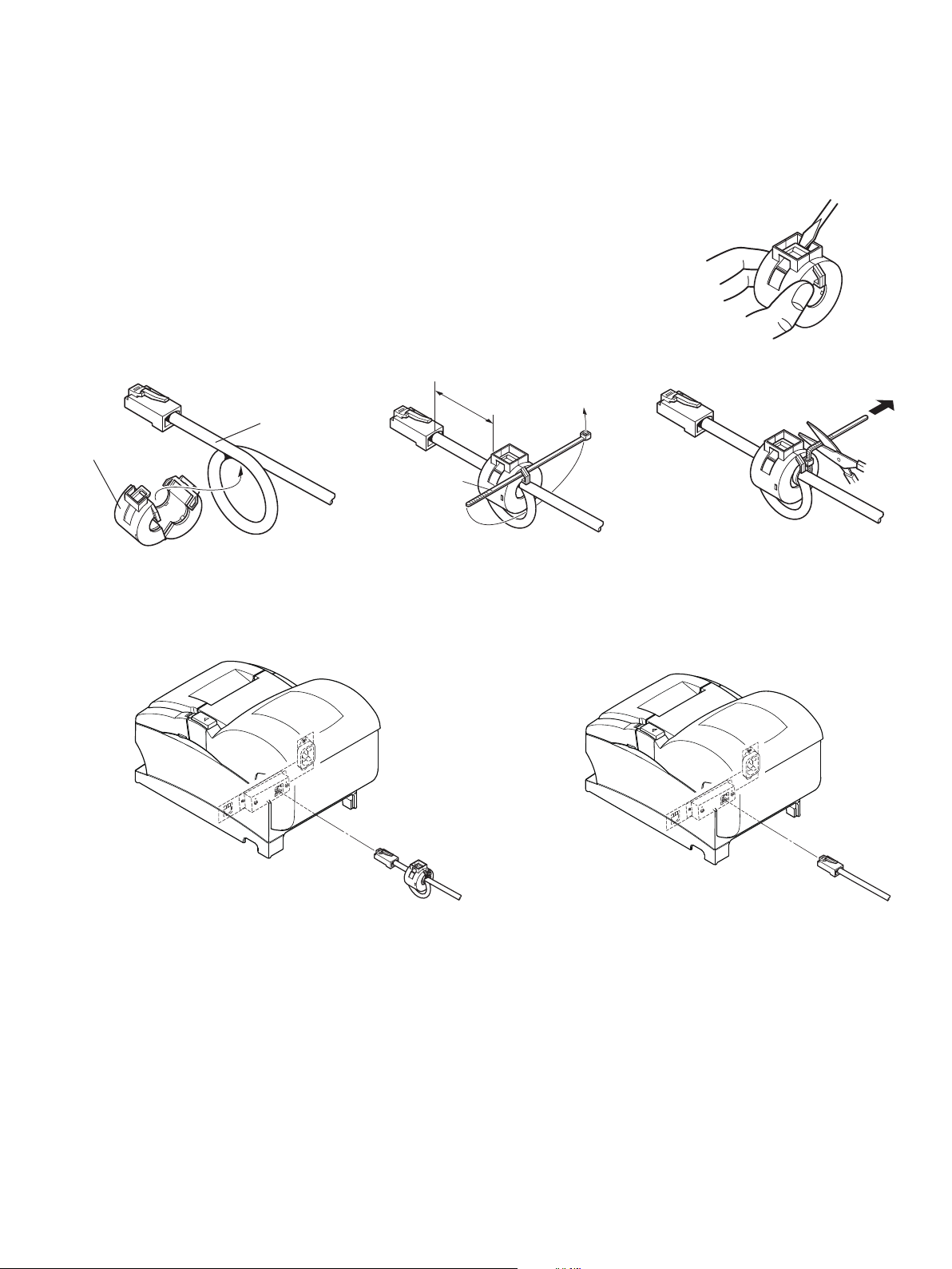
4-2-1. Parallel Interface Cable
(1) Make sure the printer is turn off.
(2) Afx the ferrite core onto the cable as shown in
the illustration.
(3) Pass the fastener through the ferrite core.
(4) Loop the fastener around the cable and lock it.
Use scissors to cut off any excess.
Ferrite core
10 cm
(maximum)
Interface cable
(5) Connect the interface cable to the connector on
the rear panel of the printer.
(6) Fasten the connector clasps.
Fastener
– 7 –
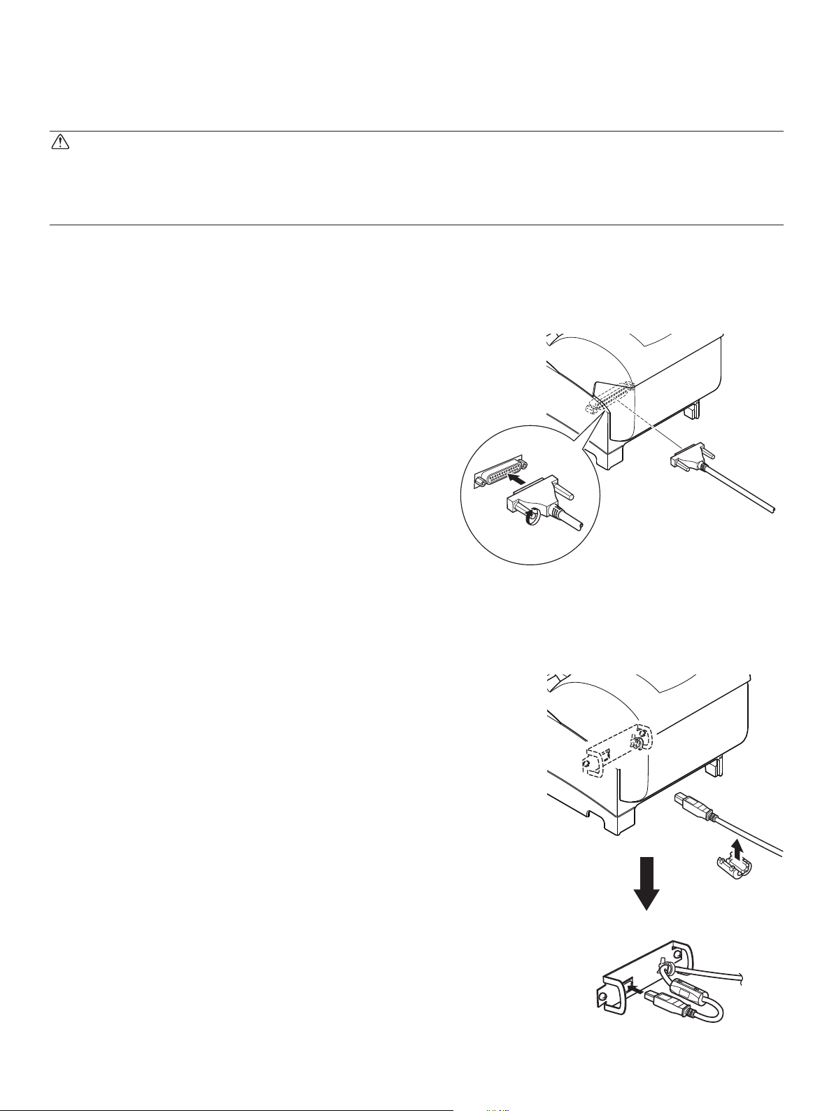
4-2-2. RS-232 Interface Cable
(1) Make sure the printer is turn off.
CAUTION
Before connecting/disconnecting the interface cable, make sure that power to the printer and
all the devices connected to the printer is turned off. Also make sure the power cable plug is
disconnected from the AC outlet.
(2) Connect the interface cable to the connector on the rear panel of the printer.
(3) Tighten the connector screws.
4-2-3. USB Interface Cable
Afx the ferrite core onto the USB cable as shown in
the illustration below and make sure to pass the cable
through the cable support as shown in the illustration.
– 8 –
4-2-4. Connecting Ethernet Cable
If a ferrite core is included, install the ferrite core onto the Ethernet cable according to the following procedure to prevent electrical noise.
If a ferrite core is not included, perform steps (1) and (5) only.
(1) Make sure the printer is turned off.
(2) Afx the ferrite core onto the ethernet cable as
shown in the illustration below.
(3) Pass the fastener through the ferrite core.
(4) Loop the fastener around the cable and lock it.
Use scissors to cut off any excess.
1 cm
(maximum)
Ethernet cable
Ferrite core
Fastener
(5) Connect the interface cable to the connector on
the rear panel of the printer.
Ethernet Interface Board
IFBD-HE06
Link disconnection detection feature
The Ethernet interface model is equipped with a link
disconnection detection feature. If the printer is turned
on when an Ethernet cable is not connected to it, the
POWER and ERROR lamps are simultaneously turned
on and off at 2-second intervals to indicate the discon
nection.
Be sure to connect the Ethernet cable from a PC or hub
to the printer, and then turn the printer on.
Ethernet Interface Board
IFBD-HE08
– 9 –
4-3. Installing the Printer Software
Here is the procedure for installing the printer driver and utility software, which are stored on
the supplied CD-ROM.
The procedure applies to the Windows operating systems shown below.
• Windows XP (SP2 or later)
• Windows Vista
• Windows 7
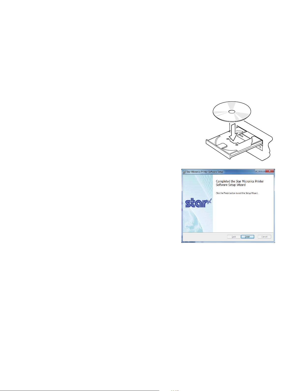
(1) Turn ON the power to your PC to start Windows.
(2) Insert the supplied CD-ROM (Drivers and Utilities)
into the CD-ROM drive.
(3) Follow the instructions that appear on the screen.
(4) The dialog shown in the illustration indicates that
the procedure has been completed.
Click “Finish”.
The dialog that appears on the screen varies with your system. This completes the installation
of the printer software. A message will appear, prompting you to restart. Restart Windows.
– 10 –
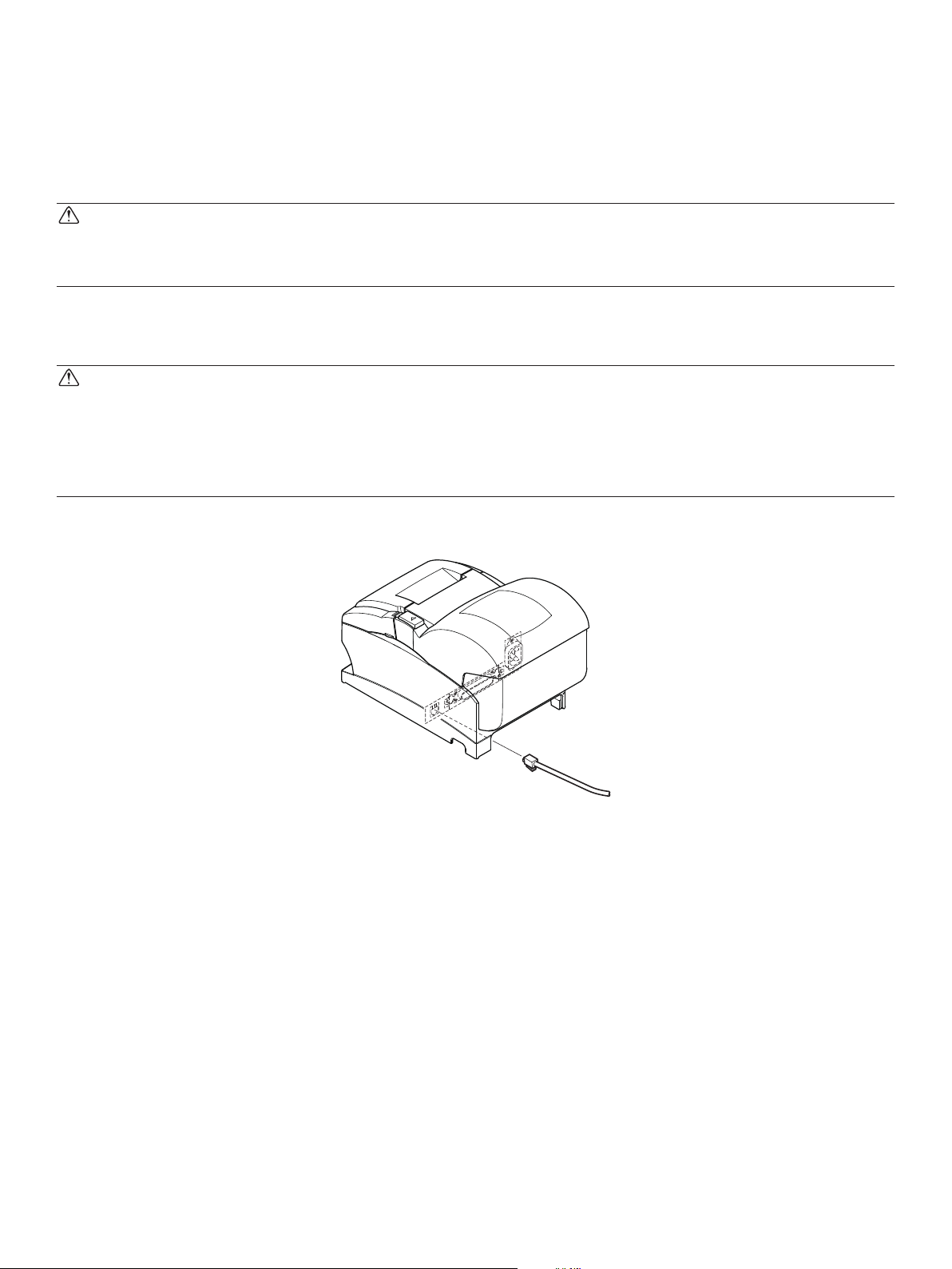
4-4. Connecting to a Peripheral Unit
You can connect a peripheral unit to the printer using a modular plug. See “Modular plug” on
page 34 for details about the type of modular plug that is required. Note that this printer does
not come with a modular plug or wire, so it is up to you to obtain one that suits your needs.
CAUTION
Make sure that the printer is turned off and unplugged from the AC outlet and that the computer
is turned off before making connections.
(1) Connect the peripheral drive cable to the connector on the rear panel of the printer.
CAUTION
Do not connect a telephone line into the peripheral drive connector. Failure to observe this may
result in damage to the printer.
Also, for safety purposes, do not connect wiring to the external drive connector if there is a
chance it may carry peripheral voltage.
– 11 –
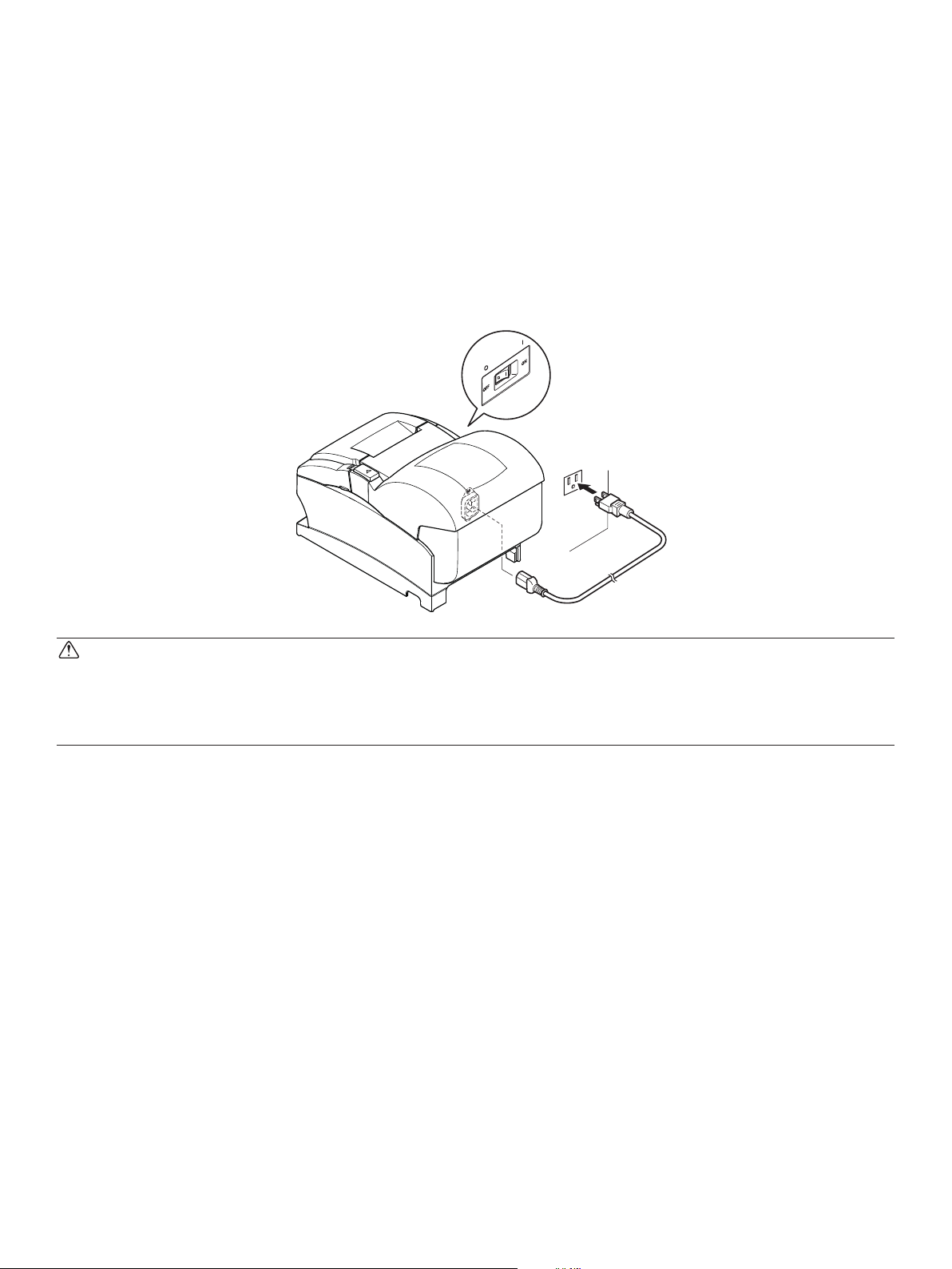
4-5. Connecting the Power Cord
Note: Before connecting/disconnecting the power cord, make sure that power to the printer
and all the devices connected to the printer is turned off. Also make sure the power
cable plug is disconnected from the AC outlet.
(1) Check the label on the back or bottom of the printer to make sure its voltage matches that
of the AC outlet. Also make sure the plug on the power cord matches the AC outlet.
(2) If the power cord is not attached to the printer, plug the appropriate end into the AC inlet
on the back of the printer.
(3) Plug the power cord into a properly grounded AC outlet.
CAUTION
If the voltage shown on the label on the of your printer does not match the voltage for your area,
contact your dealer immediately.
The power cord is designed for use with this printer only. Do not connect it to any other device.
– 12 –
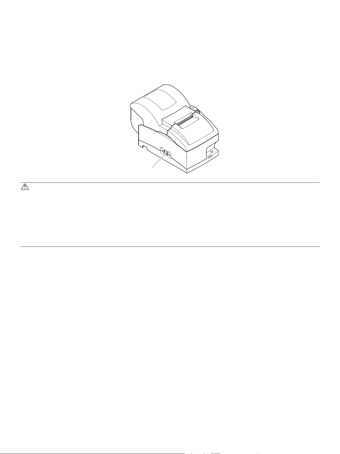
4-6. Turning Power On
Make sure that the Power cord has been connected as described in 4-5.
Turn ON the power switch located on the front of the printer.
The POWER lamp on the control panel will light up.
Power switch
CAUTION
We recommend that you unplug the printer from the power outlet whenever you do not plan to
use it for long periods. Because of this, you should locate the printer so that the power outlet it
is plugged into is nearby and easy to access.
When an Switch blind is afxed to the printer above the power switch, the ON/OFF marks of
the power switch may be hidden. If this occurs, remove the power cord from the outlet to turn
the printer OFF.
– 13 –
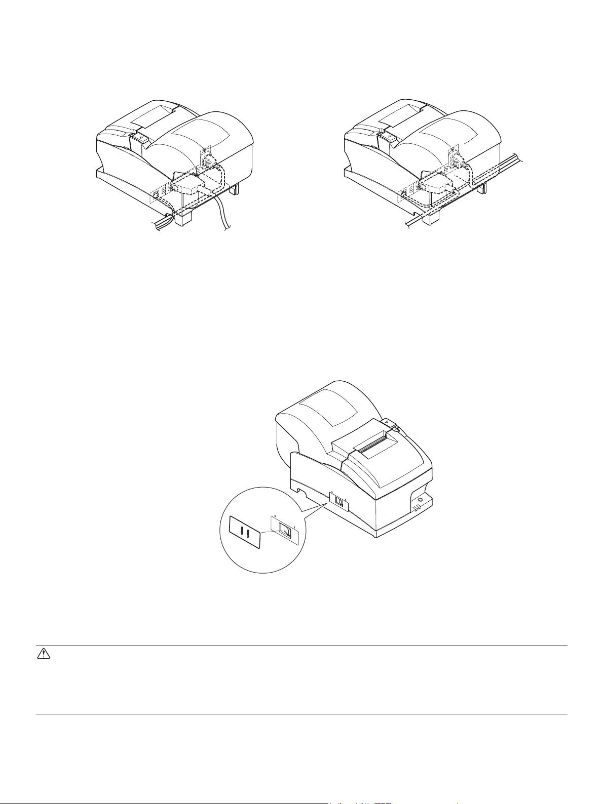
4-7. Installing the Cable
Install the cable as shown in the diagram below.
4-8. Switch Blind Installation
It is not necessary to install the switch blind. Only install it if it is necessary for you. By installing the switch blind, the following become possible.
• Preventing the power switch from being operated by mistake.
• Ensuring that other people can not easily operate the power switch.
Install the switch blind as shown in the diagram below.
The power switch can be turned ON ( | ) and OFF (O) by inserting a narrow instrument (ball pen
etc) in the holes in the switch blind.
CAUTION
We recommend that you unplug the printer from the power outlet whenever you do not plan to
use it for long periods. Because of this, you should locate the printer so that the power outlet it
is plugged into is nearby and easy to access.
– 14 –
 Loading...