

Star SP312F, SP342F-A Installation Manual

DOT MATRIX PRINTER
SP312F
SP342F-A
INST ALLA TION MANUAL
GUIDE D’INSTALLATION
AUFSTELLANLEITUNG
MANUALE DI INST ALLAZIONE


TABLE OF CONTENTS
1. UNPACKING AND INSTALLATION................................................ 2
1-1. Unpacking .................................................................................... 2
1-2. Handling Notes ............................................................................ 2
2. PARTS IDENTIFICATION AND NOMENCLATURE ...................... 3
3. FERRITE CORE INSTALLATION ..................................................... 4
4. CONNECTING THE INTERFACE CABLE .......................................6
4-1. Serial Interface Cable...................................................................6
4-2. Parallel Interface Cable................................................................ 6
APPENDIX .............................................................................................25
– 2 –
ENGLISH
1. UNPACKING AND INSTALLATION
1-1. Unpacking
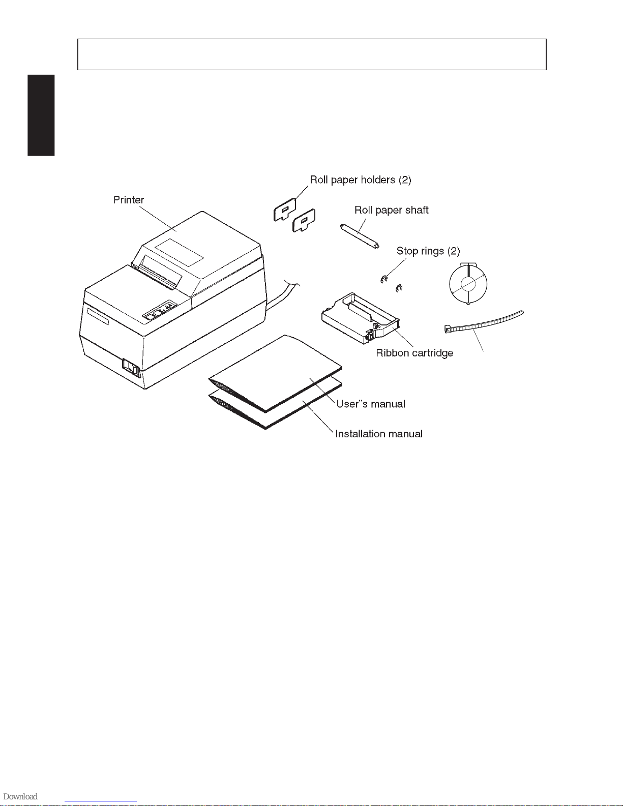
After unpacking the unit, check that all the necessary accessories are included in
the package.
Fig. 1-1 Unpacking (SP312)
1-2. Handling Notes
1. Install the unit on a stand or table which has a flat, even surface.
2. Do not connect the AC power plug to the same outlet used for other electrical
noise generating devices (such as an electrical motor, etc.)
IMPORTANT!
Install the printer near an easily accessible socket-outlet.
3. Be careful not to drop paper clips, pins or other foreign objects into the unit
as these could cause the printer to malfunction.
4. When cleaning the outer surface of the unit, wipe away dirt, foreign matter,
etc., with a soft cloth, soaked in a neutral detergent.
5. Do not attempt to print when the paper or ribbon cartridge are not loaded in
the printer as this could damage the print head.
6. Use only roll paper that is not glued to the core.
7. Do not open the front cover while printing (this is interpreted as a mechanical
error and the printer will stop).
Ferrite core
(E.U. only)
Fastener
(E.U. only)
Ø28mm

– 3 –
ENGLISH
2. PARTS IDENTIFICATION AND NOMENCLATURE
Fig. 2-1 External view of the printer (SP312)
– 4 –
ENGLISH
NOTE: Take special care when following the procedures listed below.
3. FERRITE CORE INSTALLATION
■ A ferrite core noise filter for the cash
drawer drive cable comes packed with
the printer.
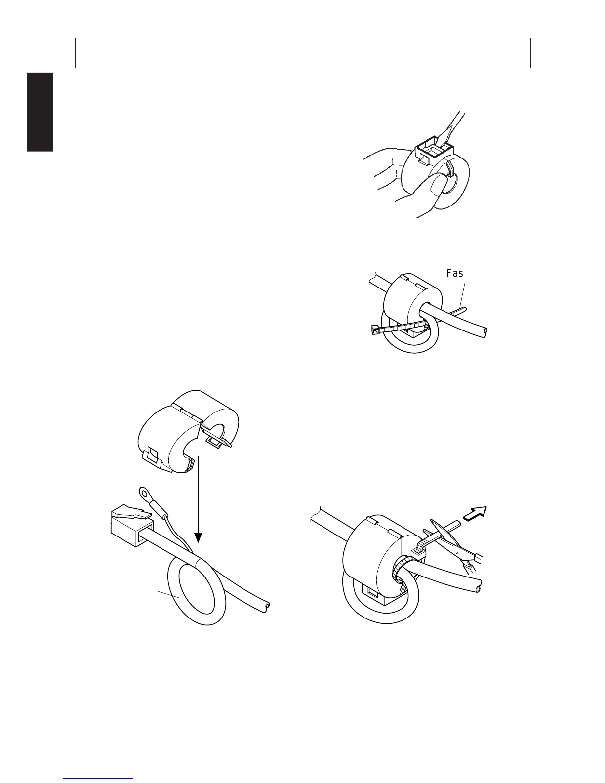
■ The ferrite core is normally packed so
it is opened, as shown in Fig. 3-2. If you
find that the ferrite core is not opened:
Use a pointed object to pry the plastic
lock of the ferrite core apart, as shown
in Fig. 3-1. When opening it, take care
not to damage the ferrite core or the
plastic lock.
Fig. 3-1
• Pass the fastener through the ferrite
core
Fig. 3-3
• Pass the fastener around the cable and
lock it.
Cut off the excess with a pair of scissors.
Fig. 3-4
Fig. 3-2
One loop
Ferrite Core (28mm diameter)
Fastener
Pull and cut
– 5 –
ENGLISH
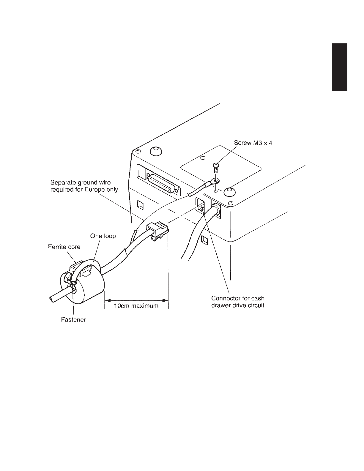
■ Clamp the ferrite core onto the cash drawer drive cable, looping the cable as
shown in Fig. 3-2.
•When installing the ferrite core be careful not to damage the cable.
•The ferrite core should be anchored firmly in place with the fastener that
comes with it, as shown in Fig. 3-3 and Fig. 3-4.
•Do not forget to loop the cable.
Fig. 3-5
– 6 –
ENGLISH
4-1. Serial Interface Cable
4. CONNECTING THE INTERFACE CABLE
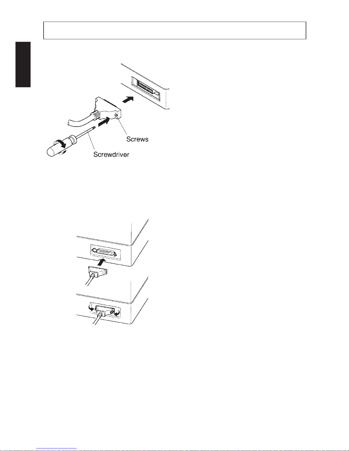
1 Turn off power for both the host
computer and the printer.
2 Insert the connector of the interface
cable into the connector on the
printer and the other end of the interface cable into the connector for
the host computer.
3 Next, tighten the screws on the con-
nectors.
Fig. 4-1 Connecting the serial interface
cable
4-2. Parallel Interface Cable
1 Turn off the power for both the host
computer and the printer.
2 Insert one connector of the interface
cable into the printer’s connector
and fasten it with the clasp, as shown
in Fig. 4-2.
3 Insert the other terminal of the inter-
face cable into the host computer’s
connector, and fasten it with the
clasp.
Fig. 4-2 Connecting the parallel interface
cable

TABLE DES MATIÈRES
1. DÉBALLAGE ET INSTALLATION ................................................... 8
1-1. Déballage ..................................................................................... 8
1-2. Remarques concernant la manipulation ....................................... 8
2. IDENTIFICATION DES PIÈCES ET NOMENCLATURE ................9
3. INSTALLATION DU NOYAU EN FERRITE ..................................10
4. CONNEXION DU CÂBLE D’INTERFACE .....................................12
4-1. Câble d’interface sériel ..............................................................12
4-2. Câble d’interface parallèle .........................................................12
APPENDICE ........................................................................................... 25
L’appendice n’est pas traduit.

– 8 –
FRANÇAIS
1. DÉBALLAGE ET INSTALLATION
1-1. Déballage
Après avoir déballé l’appareil, vérifiez si vous disposez bien de tous les accessoires illustrés ci-après.
Fig. 1-1 Déballage (SP312)
1-2. Remarques concernant la manipulation
1. Installez l’appareil sur un support ou sur une table dont la surface est plate et
uniforme.
2. Ne branchez pas l’appareil à la même prise secteur que d’autres appareils
produisant des bruits électriques (appareils ayant un moteur électrique, etc.).
IMPORTANT !
Installez l’imprimante le plus près possible d’une prise secteur facilement
accessible.
3. Veillez à ne pas laisser tomber des trombones, punaises ou autres objets dans
l’appareil, cela risque de causer un mauvais fonctionnement.
4. Nettoyez la surface de l’imprimante à l’aide d’un chiffon doux humidifié et
d’un détergent neutre.
5. Ne lancez pas l’impression si le papier ou la cartouche de ruban ne sont pas
installés, sous peine d’endommager la tête d’impression.
6. N’utilisez jamais un rouleau de papier dont l’extrémité est collée au rouleau
central.
7. N’ouvrez pas le cache avant de l’appareil pendant l’impression ; en effet cela
serait interprété comme étant une erreur mécanique et l’impression s’interromprait automatiquement.
– 9 –
FRANÇAIS
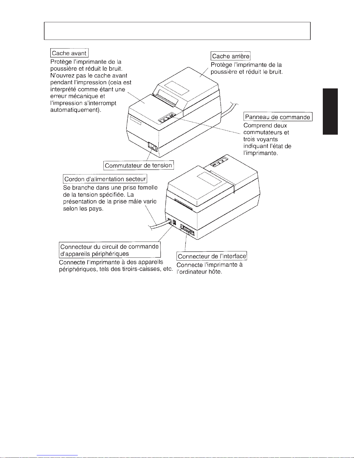
2. IDENTIFICATION DES PIÈCES ET NOMENCLATURE
Fig. 2-1 Vue externe de l’imprimante (SP312)
 Loading...