

Page 1

DOT MATRIX PRINTER
SP200F SERIES
USERS MANUAL
MODE D’EMPLOI
BEDIENUNGSANLEITUNG
MANUALE DI ISTRUZIONI
Page 2

Federal Communications Commission
Radio Frequency Interference
Statement
This equipment has been tested and found to comply with the limits for a Class A digital
device, pursuant to Part 15 of the FCC Rules. These limits are designed to provide
reasonable protection against harmful interference when the equipment is operated in a
commercial environment. This equipment generates, uses and can radiate radio frequency
energy and, if not installed and used in accordance with the instruction manual, may cause
harmful interference to radio communications. Operation of this equipment in a residential
area is likely to cause harmful interference in which case the user will be required to correct
the interference at his own expense.
For compliance with the Federal Noise Interference Standard, this equipment requires a
shielded cable.
This statement will be applied only for the printers marketed in U.S.A.
Statement of
The Canadian Department of Communications
Radio Interference Regulations
This digital apparatus does not exceed the Class A limits for radio noise emissions from
digital apparatus set out in the Radio Interference Regulations of the Canadian Department
of Communications.
Le présent appareil numérique n’émet pas de bruits radioélectriques dépassant les limites
applicables aux appareils numériques de la classe A prescrites dans le Règlement sur le
brouillage radioélectrique édicté par le ministère des Communications du Canada.
The above statement applies only to printers marketed in Canada.
CE
Manufacturer’s Declaration of Conformity
EC Council Directive 89/336/EEC of 3 May 1989
This product, has been designed and manufactured in accordance with the International
Standards EN 50081-1/01.92 and EN 50082-1/01.92, following the provisions of the
Electro Magnetic Compatibility Directive of the European Communities as of May 1989.
EC Council Directive 73/23/EEC and 93/68/EEC of 22 July 1993
This product, has been designed and manufactured in accordance with the International
Standards EN 60950, following the provisions of the Low Voltage Directive of the
European Communities as of July 1993.
The above statement applies only to printers marketed in EU.
Trademark acknowledgments
SP200F Series: Star Micronics Co. Ltd.
VeriFone: VeriFone, Inc.
ESC/POS: Seiko Epson Corporation
Notice
• All rights reserved. Reproduction of any part of this manual in any form whatsoever,
without STAR’s express permission is forbidden.
• The contents of this manual are subject to change without notice.
• All efforts have been made to ensure the accuracy of the contents of this manual at the
time of going to press. However, should any errors be detected, STAR would greatly
appreciate being informed of them.
• The above notwithstanding, STAR can assume no responsibility for any errors in this
manual.
©
Copyright 1994, 1997 Star Micronics Co., LTD.
Page 3

TABLE OF CONTENTS
1. Outline ...............................................................................................................1
2. Unpacking and Installation................................................................................2
2-1. Unpacking ..............................................................................................2
2-2. Locating the printer ................................................................................3
2-3. Handling Care ........................................................................................3
2-4. Maintenance ...........................................................................................3
3. Parts Identification and Nomenclature ..............................................................4
4. Loading the Ribbon Cartridge and Paper ..........................................................6
4-1. SP210 type .............................................................................................6
4-2. SP240 type .............................................................................................9
4-3. Removing the Paper .............................................................................14
4-4. Connecting the Interface Cable............................................................14
5. Control Panel ...................................................................................................16
5-1. Basic Operation....................................................................................16
5-2. Switch Operation (Combined Switch Operation) ................................17
6. Control Codes ..................................................................................................19
STAR mode..................................................................................................19
6-1. Control Codes Used in Character Setting ............................................19
6-2. Control Codes Used in Print Mode Setting..........................................19
6-3. Control Codes Used in Line Spacing...................................................19
6-4. Control Codes Used for Peripheral Units ............................................20
6-5. Auto Cutter Control .............................................................................20
6-6. Other Control Codes ............................................................................20
Appendix A: Serial Interface...............................................................................87
A-1. Connectors and Signals ........................................................................87
A-2. Interface Connections ..........................................................................88
A-3. Dip Switch Setting ...............................................................................89
A-4. Communication Protcol .......................................................................90
Appendix B: Parallel Interface ............................................................................92
B-1. Interface Specifications........................................................................92
B-2. Interface Timing...................................................................................92
B-3. Connectors and Signals ........................................................................93
B-4. Dip Switch Setting ...............................................................................94
Appendix C: Peripheral Unit Drive Circuit.........................................................95
Appendix D: General Specifications ...................................................................97
Appendix E: Character Font Table....................................................................100
E-1. U.S.A..................................................................................................100
E-2. Europe ................................................................................................102
E-3. International Character Sets ...............................................................104
Page 4
– 1 –
ENGLISH
The SP200 Series Serial Impact Dot Matrix Printer is designed for use with
electronic instruments such as POS, banking equipment, computer peripheral
equipment, etc.
The major features of the SP200 Series are as follows:
1. Bi-directional printing at approx. 2.5 lines/sec.
2. Serial interface or Parallel interface.
3. The data buffer allows the unit to receive print data even during printing.
4. Peripheral unit drive circuit enables control of external devices such as cash
drawers.
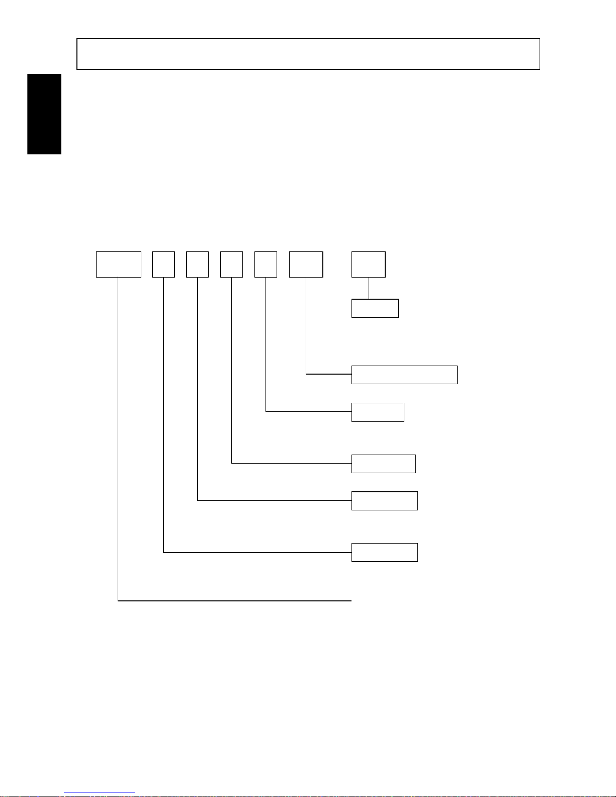
SP2 1 2 F D 42 – 120
Voltage
120 : 120VAC
230 : 230VAC
240 : 240VAC
No. of print columns
42 : 42 columns (16 CPI)
Interface
D : Serial interface (RS-232C)
C : Parallel interface
Paper feed
F : Friction paper feed method
Mechanism
2 : Single color, 42 columns (16 CPI)
6 : Two color, 42 columns (16 CPI)
Printer type
1 : Standard type
4 : Auto cutter equipped type
SP200 Series printer
1. Outline
Page 5
– 2 –
ENGLISH
2. Unpacking and Installation
2-1. Unpacking
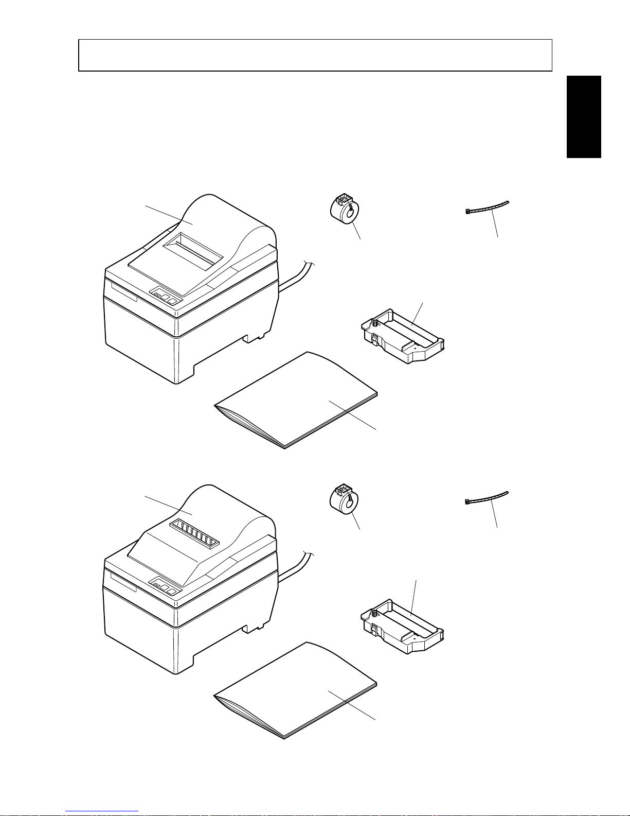
After unpacking the unit, check that all the necessary accessories are included in
the package.
SP210 type
SP240 type
Fig. 2-1 Unpacking
User´s manual
Ribbon cartridge
Printer
Ferrite core
(EU only)
Fastener
(EU only)
Printer
User´s manual
Ribbon cartridge
Ferrite core
(EU only)
Fastener
(EU only)
Page 6

– 3 –
ENGLISH
2-2. Locating the printer
When you locate your printer, keep the following tips in mind:
1. Protect your printer from excessive heat such as direct sunlight or heaters, and
keep it away from moisture and dust.
2. Place the printer on a firm, level surface which is fairly vibration-free.
3. A steady power supply that is not subject to power surges should be connected
to the printer.
For example, do not connect it to the same circuit as a large, noise-producing
appliance such as a refrigerator or an air conditioner.
4. Make sure the line voltage is the voltage specified on the printer’s identification plate.
5. To disconnect the printer, the plug has to be disconnected from the wall socket,
which has to be located close to the printer, and easy to access.
2-3. Handling Care
1. Be careful not to drop paper clips, pins or other foreign matter into the unit as
these cause the printer to malfunction.
2. Do not attempt to print when either paper or ribbon cartridge is not located in
the printer, otherwise the print head can be damaged.
3. Do not open the cover while printing.
4. Do not touch the print head immediately after printing as it gets very hot.
5. Use only roll paper that is not glued to the core.
6. When the paper end mark appears on the paper, replace the roll paper before
it runs out.
2-4. Maintenance
Essentially, your printer is a robust piece of equipment, but should be treated with
a modicum of care in order to avoid malfunctions. For example:
1. Keep your printer in a “comfortable” environment. Roughly speaking, if you
feel comfortable, then the environment is suitable for your printer.
2. Do not subject the printer to physical shocks or excessive vibration.
3. Avoid over-dusty environments. Dust is the enemy of all precision mechanical devices.
4. To clean the exterior of the printer, use a cloth barely dampened with either
water with a little detergent or a little alcohol, but do not allow any liquid to
fall inside the printer.
5. The interior of the printer may be cleaned with a small cleaner or a compressed-air aerosol (sold for this purpose). When performing this operation,
be sure not to bend or damage any cable connections or electronic components.
Page 7
– 4 –
ENGLISH
3. Parts Identification and Nomenclature
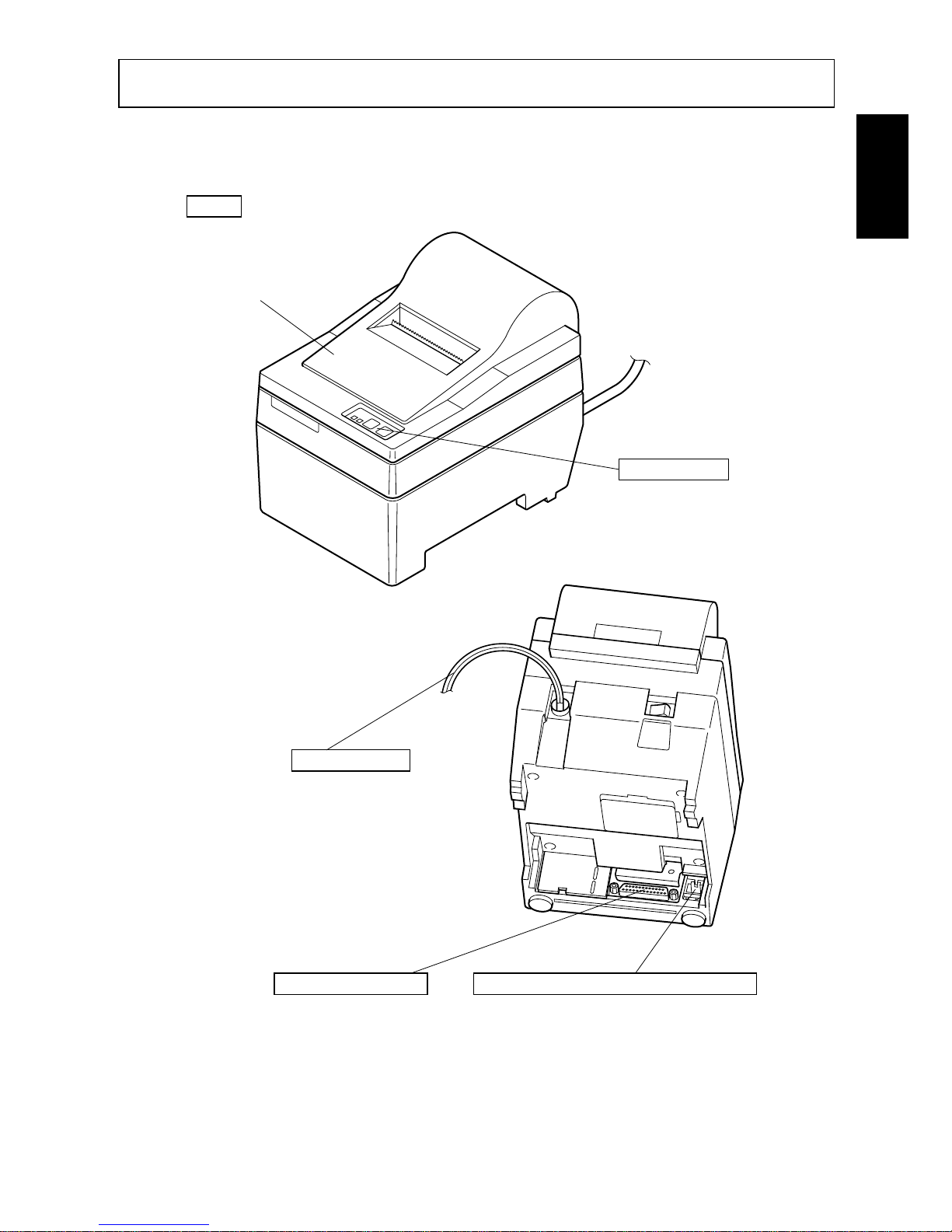
SP210 type
Fig. 3-1 External view of the printer (SP210 type)
Features two control
switches and two
indicators to indicate
printer status.
Control panel
Protects the printer from
dust and reduces noise.
Do not open the cover
while printing.
Cover
Connects the printer
with host computer.
Interface connector
Connects to peripheral units such
as cash drawers, etc.
Do not connect this to a telephone.
Peripheral unit drive circuit connector
Plugs into an outlet of
the specified voltage.
Shape of AC power plug
will vary according to
destinations.
AC power cord
Page 8
– 5 –
ENGLISH
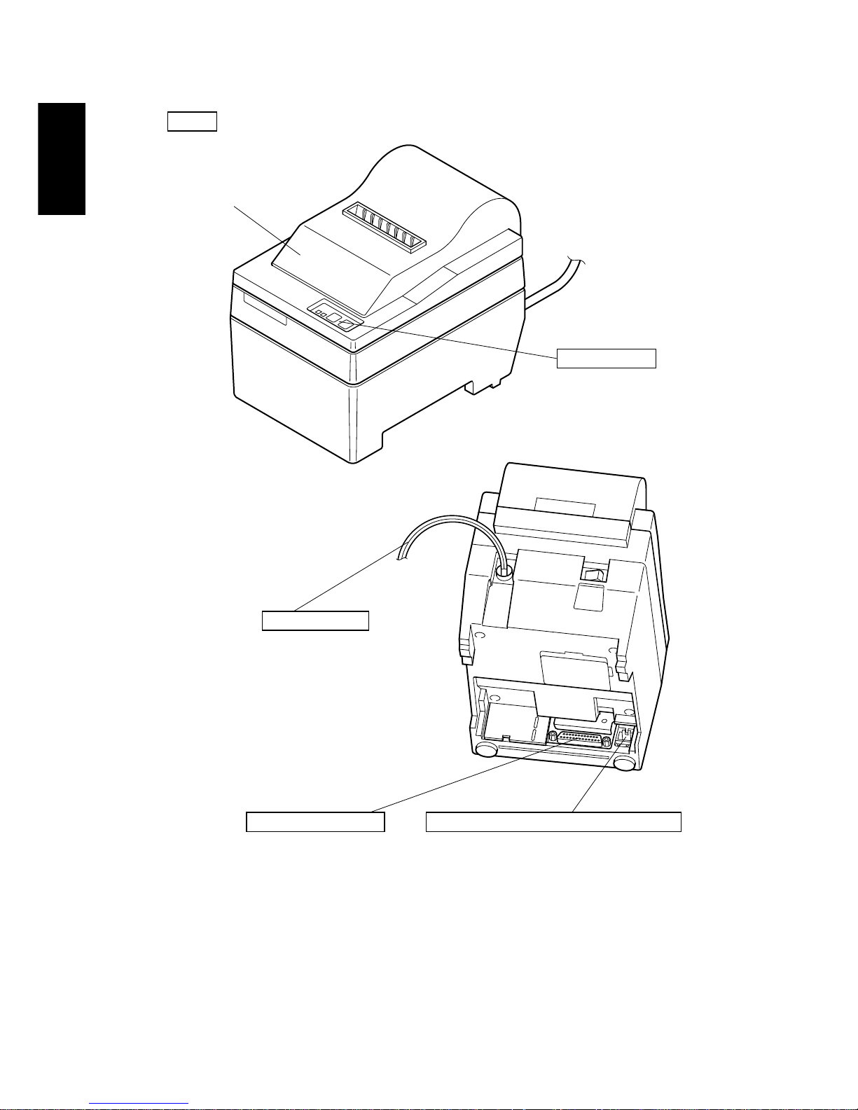
SP240 type
Fig. 3-2 External view of the printer (SP240 type)
Features two control
switches and two
indicators to indicate
printer status.
Control panel
Connects the printer
with host computer.
Interface connector
Connects to peripheral units such
as cash drawers, etc.
Do not connect this to a telephone.
Peripheral unit drive circuit connector
Protects the printer from
dust and reduces noise.
Do not open the cover
while printing.
Cover
Plugs into an outlet of
the specified voltage.
Shape of AC power plug
will vary according to
destinations.
AC power cord
Page 9
– 6 –
ENGLISH
4. Loading the Ribbon Cartridge and Paper
4-1. SP210 type
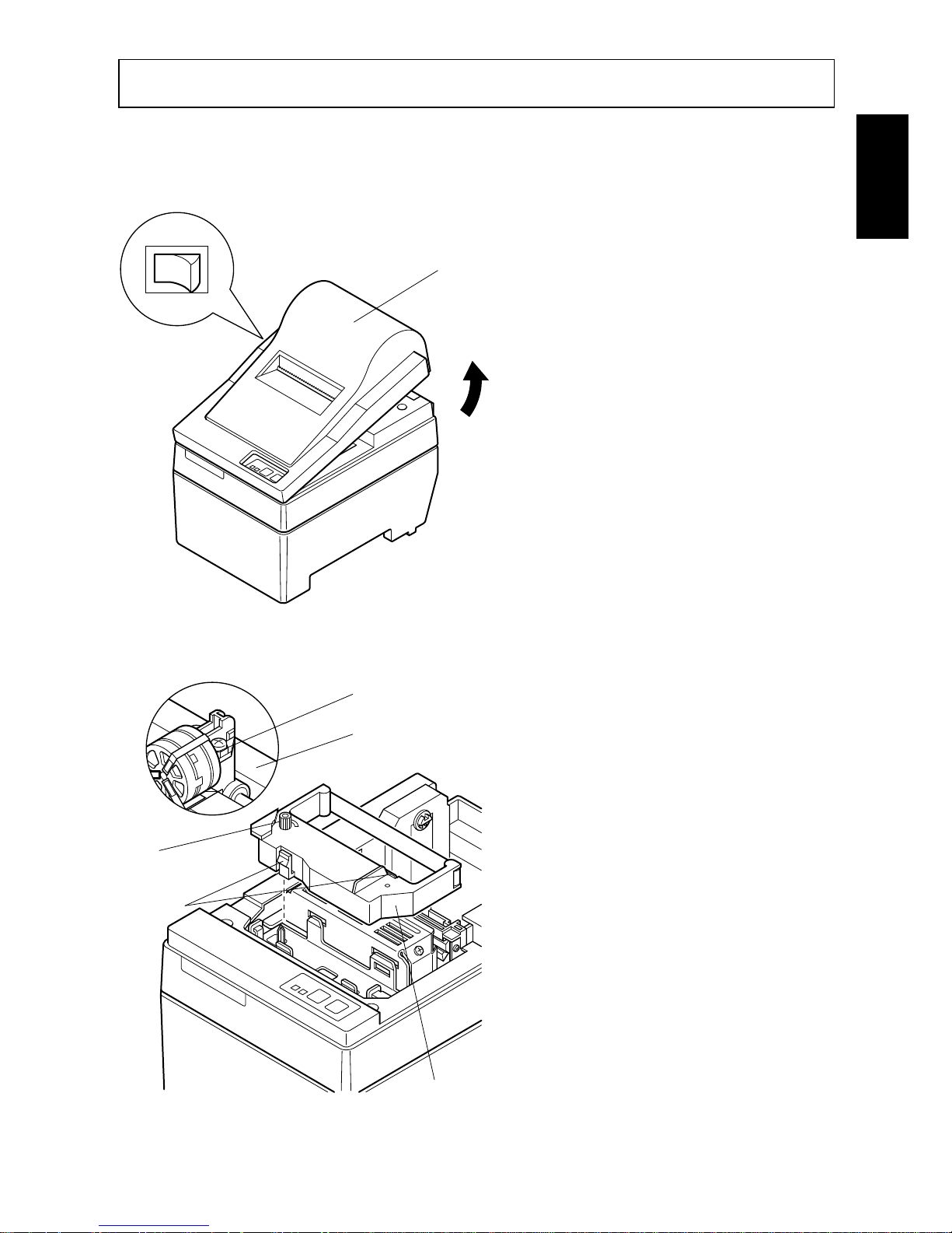
4-1-1.Loading the Ribbon Cartridge
1 Turn off power to the printer.
2 Lift the cover up approx. 3 cm.
Hold the cover tilted at this angle, then pull it toward you to
remove it.
3 Place the ribbon cartridge in the
direction shown in Fig. 4-2 and
press it down to load it. If loading
of the ribbon cartridge is not satisfactory, press down the cartridge while rotating the ribbon
feed knob in the direction of the
arrow.
4 Turn the ribbon feed knob of the
ribbon cartridge in the direction
of the arrow to remove slack in
the ribbon.
5 Mount the cover by reversing the
procedure outlined in step 2
above.
Fig. 4-1 Removing the cover
Cover
Power off
Print head
Ink ribbon
Ribbon cartridge
Ribbon feed
knob
Notched
part
Fig. 4-2 Loading the ribbon cartridge
Page 10
– 7 –
ENGLISH
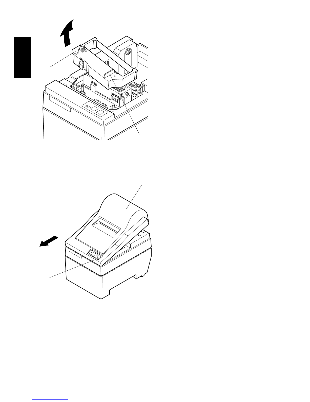
Note: When removing the ribbon car-
tridge, raise the A section and
then remove it by holding the B
section as shown in Fig. 4-3.
A
B
Fig. 4-3
4-1-2.Loading the Paper
1 Lift the cover up approx. 3cm. Hold
the cover tilted at this angle, then
pull it toward you to remove it.
Cover
FEED
switch
Fig. 4-4 Removing the cover
Page 11
– 8 –
ENGLISH
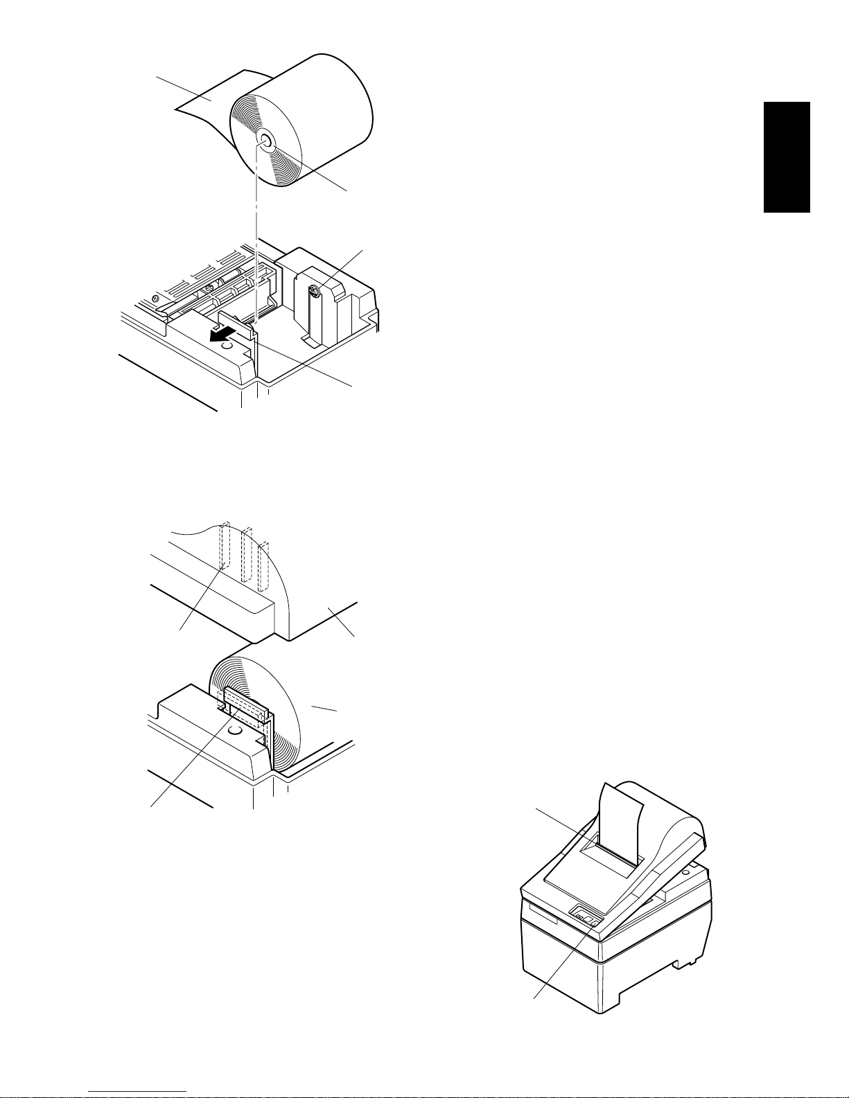
2 Cut off the front edge of the roll
paper perpendicularly.
3 Confirm that the power of the printer
is turned on.
4 While observing the direction of the
roll paper, insert the top end of the
paper beneath the paper guide as far as
it will go. If the roll paper is installed,
the top end of the paper automatically
comes out from the paper exit.
5 Move the paper roll holder in the
direction of the arrow, and insert the
roll so that the holes in the core align
with the axes of the paper roll holder.
Release the paper roll holder to secure the paper.
6 If the paper roll core has not been
properly aligned with the paper roll
holder, the cover cannot to properly
seated until the paper position is
corrected.
7 Press the FEED (paper feed) switch to
feed the paper approximately 10cm.
8 Insert the top edge of the paper into
the tear bar slot, then mount the cover
by reversing the procedure for removing the cover in step 1 above.
Note: When the paper end mark ap-
pears on the paper, replace the
roll paper before it runs out.
Fig. 4-7
Positioning rib
Cover
Roll paper
Paper roll holder
Roll paper
Core
Axis
Paper roll holder
Fig. 4-5 Loading the paper
Fig. 4-6
FEED switch
Tear bar
Page 12
– 9 –
ENGLISH
4-2. SP240 type
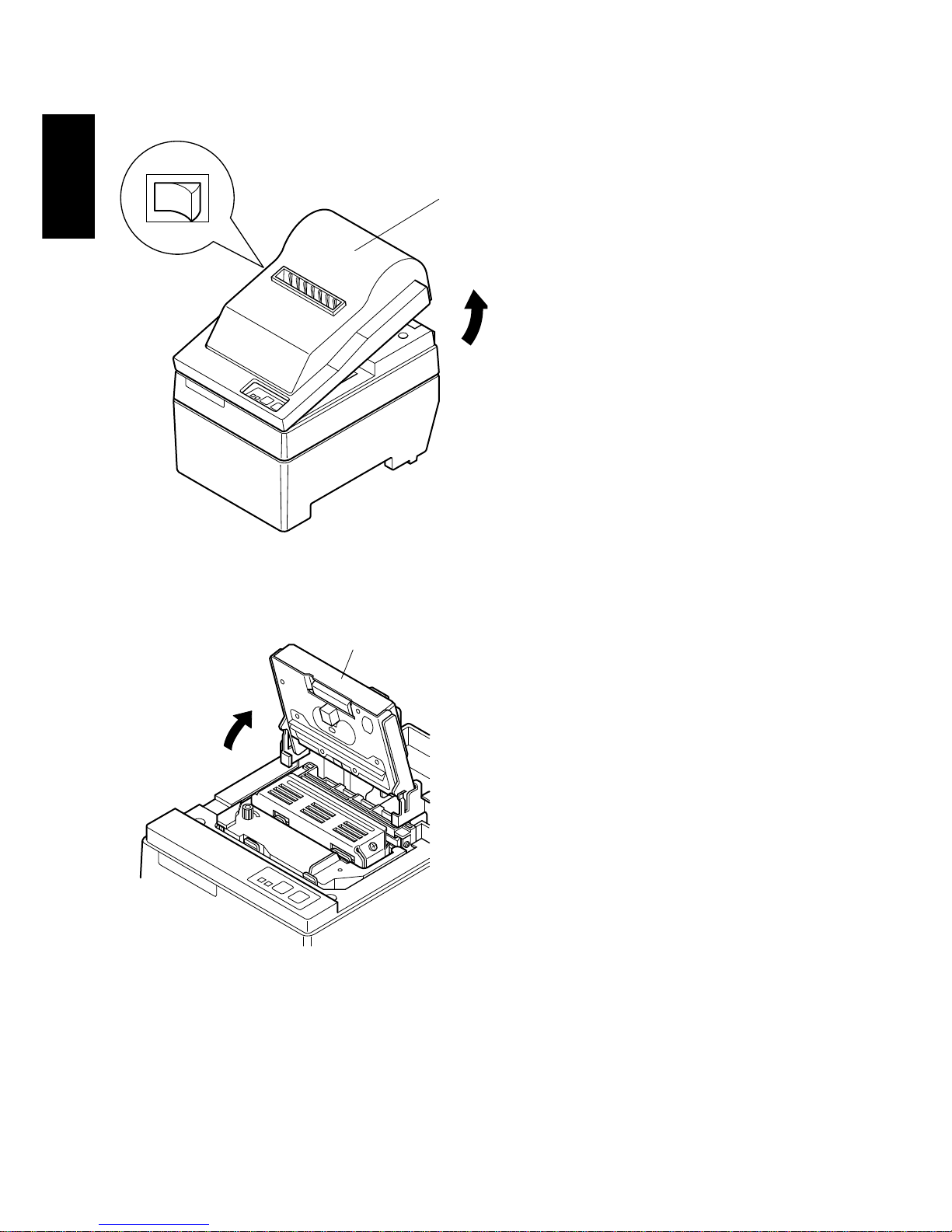
4-2-1.Loading the Ribbon Cartridge
1 Turn off power to the printer.
2 Lift the cover up approx. 3 cm.
Hold the cover tilted at this angle, then pull it toward you to
remove it.
3 Lift up the auto cutter and put it in
a vertical position, as shown in
Fig. 4-9.
Cover
Power off
Fig. 4-8 Removing the cover
Auto cutter
Fig. 4-9 Raise the auto cutter
Page 13
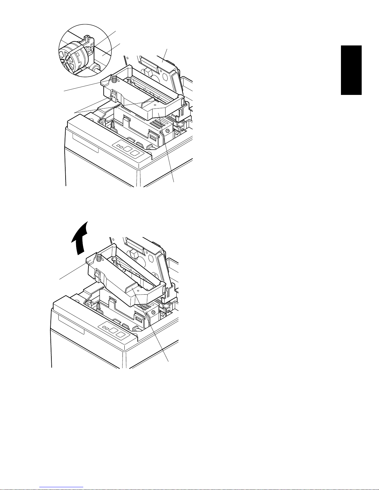
– 10 –
ENGLISH
4 Place the ribbon cartridge in the
direction shown in Fig. 4-10 and
press it down to load it. If loading
of the ribbon cartridge is not satisfactory, press down the cartridge while rotating the ribbon
feed knob in the direction of the
arrow.
5 Turn the ribbon feed knob of the
ribbon cartridge in the direction
of the arrow to remove slack in
the ribbon.
6 Close the Auto Cutter.
7 Mount the cover by reversing the
procedure outlined in step 2
above.
Note: When removing the rib-
bon cartridge, raise the A
section and then remove
it by holding the B section
as shown in Fig. 4-11.
Fig. 4-10 Loading the ribbon cartridge
Print head
Ink ribbon
Auto cutter
Ribbon cartridge
Ribbon feed
knob
Notched
part
A
B
Fig. 4-11
Page 14
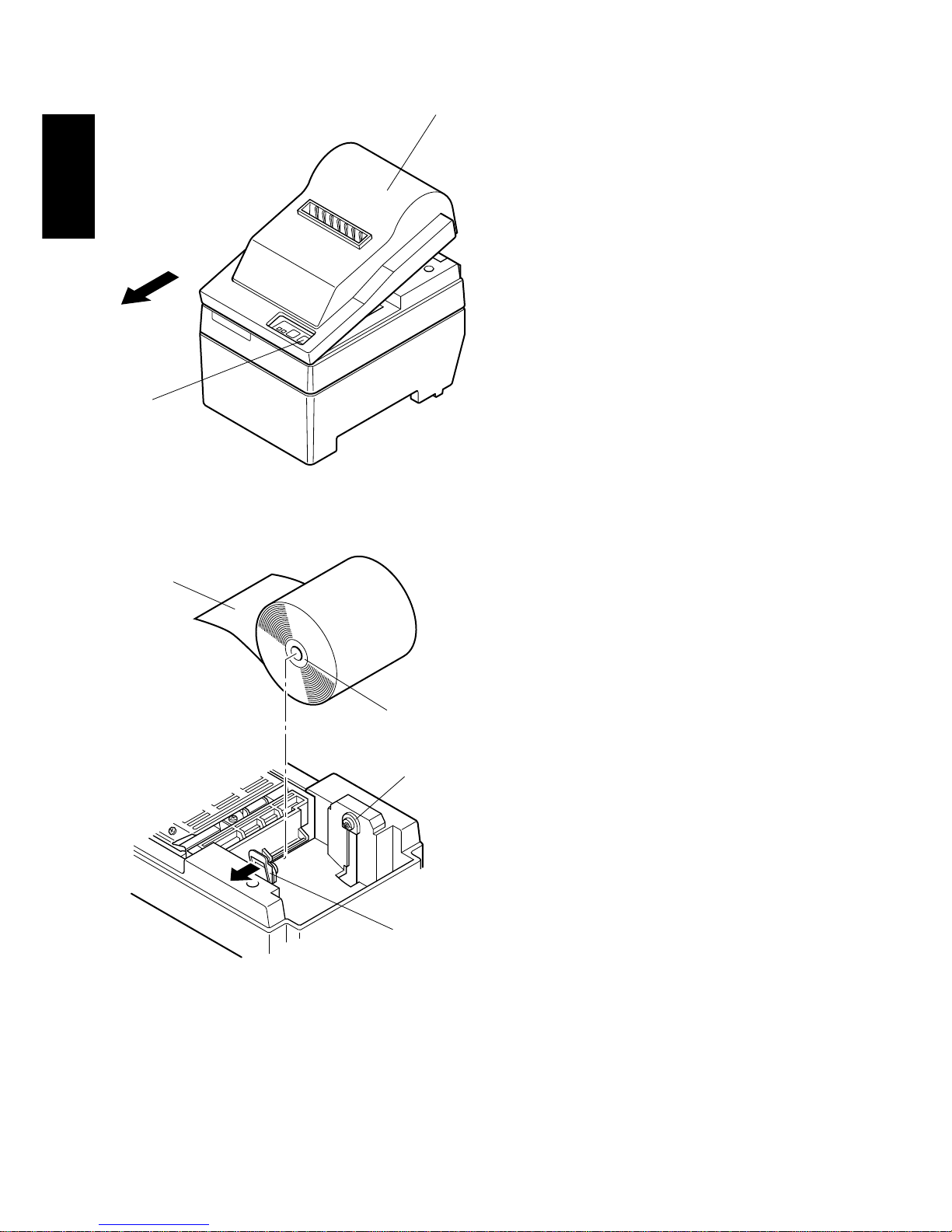
– 11 –
ENGLISH
4-2-2.Loading the Paper
1 Lift the cover up approx. 3cm. Hold
the cover tilted at this angle, then
pull it toward you to remove it.
2 Cut off the front edge of the roll
paper perpendicularly.
3 Confirm that the power of the printer
is turned on.
4 While observing the direction of the
roll paper, insert the top end of the
paper beneath the paper guide as far as
it will go. If the roll paper is installed,
the top end of the paper automatically
comes out from the paper exit. After
2cm of paper are fed out, the paper
is automatically cut off.
5 Move the paper roll holder in the
direction of the arrow, and insert the
roll so that the holes in the core align
with the axes of the paper roll holder.
Release the paper roll holder to secure the paper.
6 If the paper roll core has not been
properly aligned with the paper roll
holder, the cover cannot to properly
seated until the paper position is
corrected.
Cover
FEED
switch
Fig. 4-12 Removing the cover
Roll paper
Core
Axis
Paper roll holder
Fig. 4-13 Loading the paper
Page 15
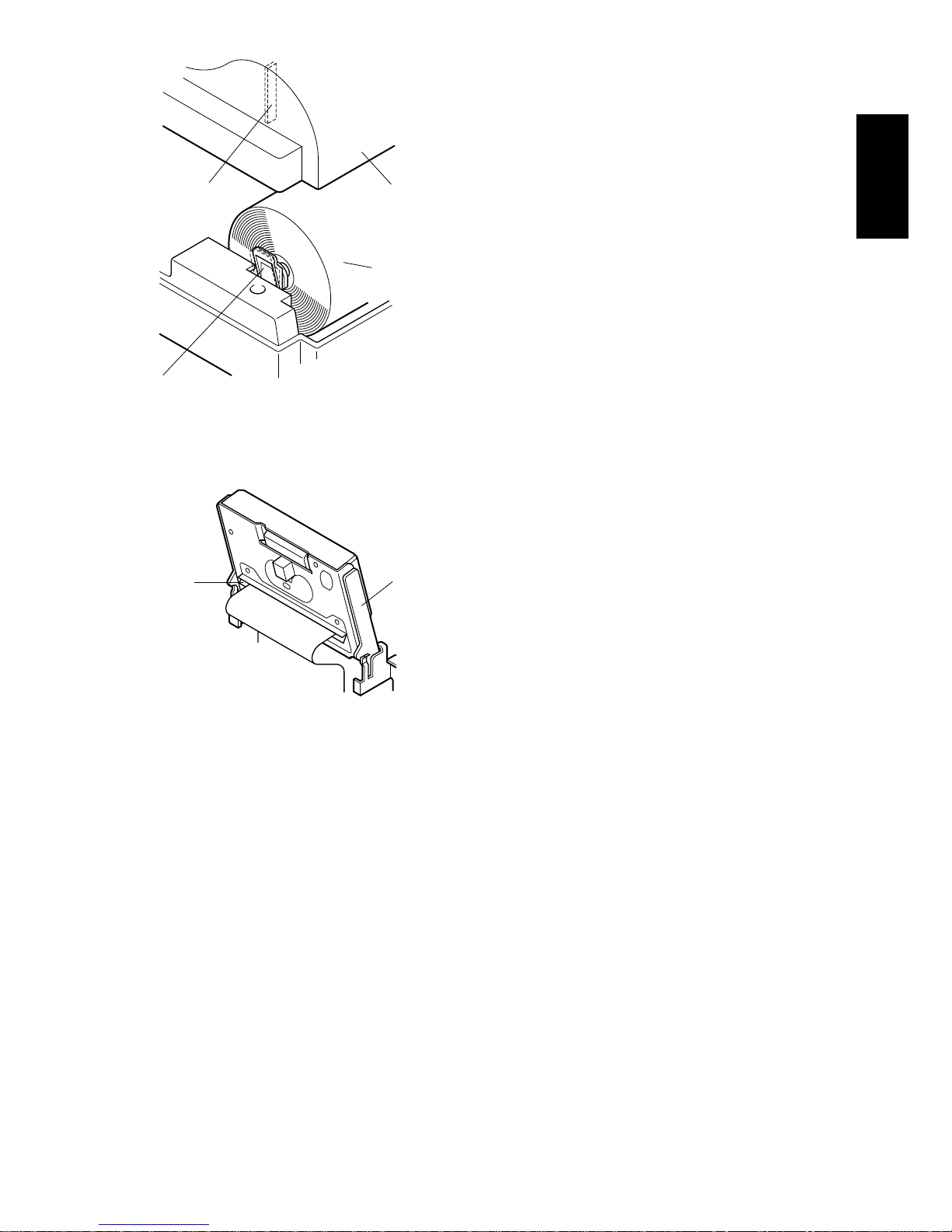
– 12 –
ENGLISH
7 Press the FEED (paper feed) switch
to feed the paper approximately
10cm.
8 Insert the tip of the roll paper in the
auto cutter paper slit.
• When using copying paper, insert
only the original (the upper paper)
into the slit of the auto cutter. Insert
the paper which is to be copied (the
lower paper) between the platen and
the auto cutter.
Fig. 4-14
Positioning rib
Cover
Roll paper
Paper roll holder
Paper
insertion
slit
Auto
cutter
Fig. 4-15 Insertion of the paper into
the auto cutter
Page 16
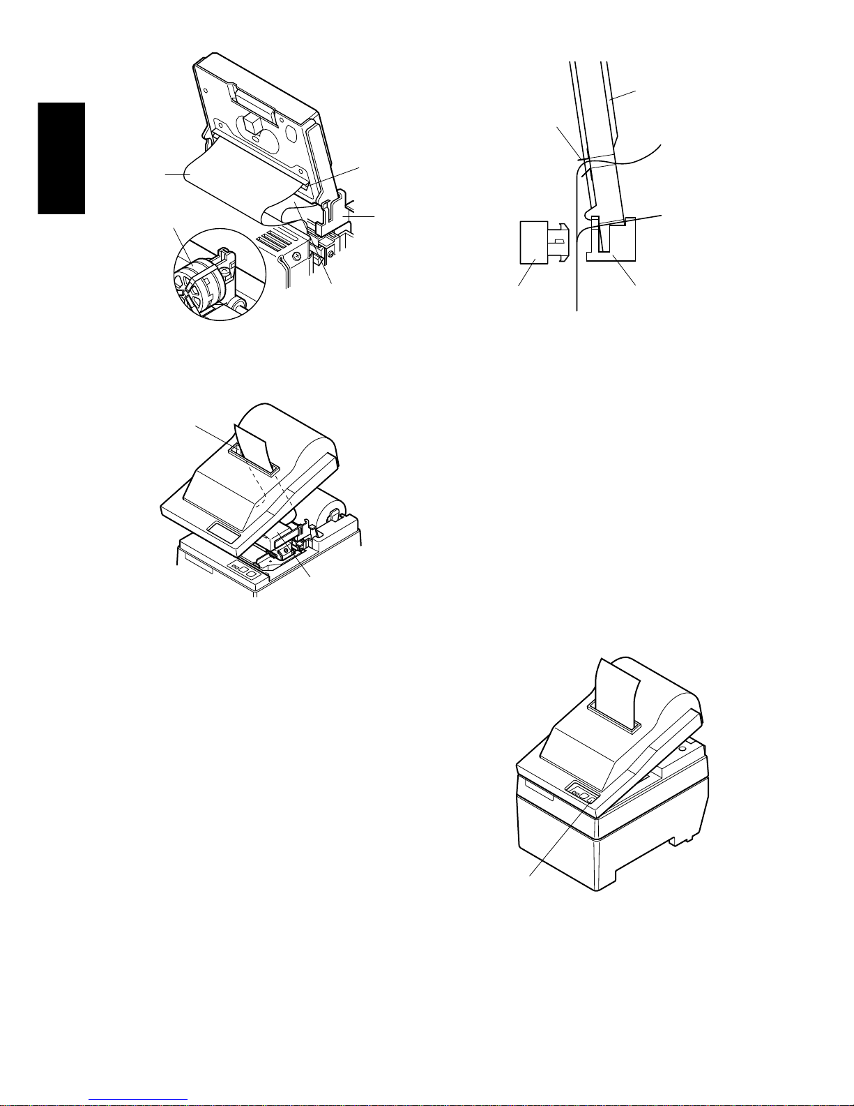
– 13 –
ENGLISH
Fig. 4-16 Insertion of the paper into the auto cutter
(When using copying paper)
9 Pull on the edge of the paper to
remove any slack and then lower the
auto cutter.
0 Insert the paper through the paper
outlet and then replace the cover by
reversing the removal steps.
Note: When the paper end mark ap-
pears on the paper, replace the
roll paper before it runs out.
Fig. 4-18
Paper
outlet
Auto cutter
Fig. 4-17 Paper outlet of the front
cover
Paper insertion
slit
Platen
Lower paper
Upper
paper
Print head
Print head
Paper insertion
slit
Auto cutter
Platen
Lower paper
Upper paper
FEED switch
Page 17
– 14 –
ENGLISH
4-3. Removing the Paper
Remove the cover, then cut off the paper near the rear of the paper guide and press
the FEED switch to feed out the paper remaining in the unit.
When the paper runs out, the POWER lamp will blink.
Note 1. Remove the paper remaining in the printer by pressing the FEED
switch.
2. When the paper end mark appears on the paper, replace the roll
paper before it runs out.
3. When removing the core of the roll paper, open the roll paper
holder.
4-4. Connecting the Interface Cable
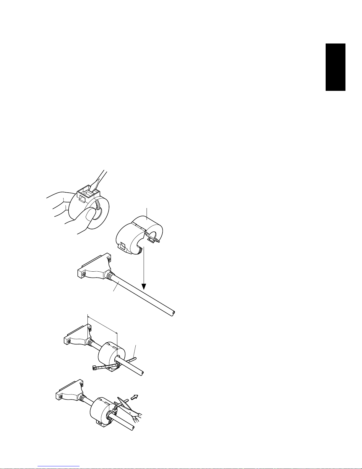
4-4-1.Ferrite core installation (EU only)
1 Affix the ferrite core onto the serial/
parallel interface cable as shown in
the illustration.
If a ferrite core is not open, use a
screw driver to pry it apart, taking
care not to damage the core or lock.
2 Pass fastener through ferrite core.
3 Pass fastener around cable and lock
it.
Cut off excess with scissors.
Attach the ferrite core only to the
cables of printers sold in the EU.
Ferrite core
Interface cable
Fig. 4-19
Pull and cut
5cm
maximum
Fastener
Page 18
– 15 –
ENGLISH
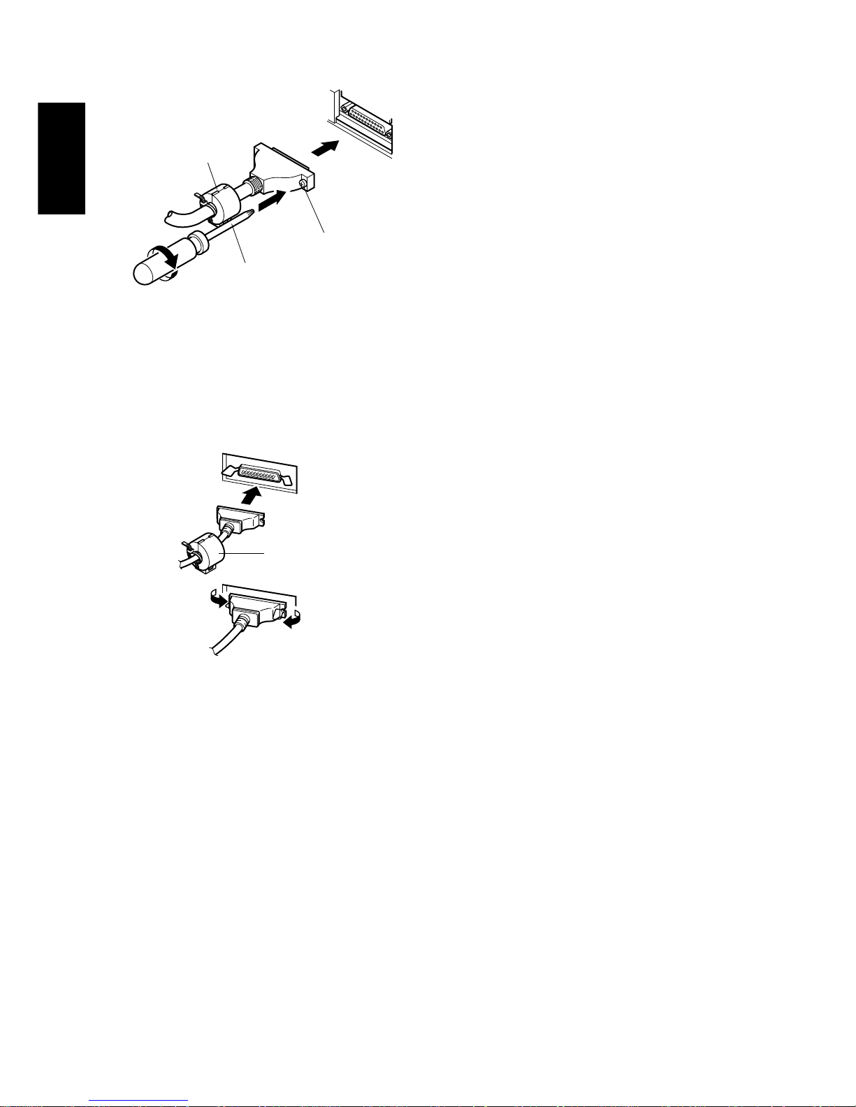
4-4-2.Serial Interface Cable
1 Turn off power to both the host
computer and the printer.
2 Insert the connector at one end of
the interface cable into the connector on the printer and the other connector into the connector for the
host computer.
3 Next, fasten the right and left screws
for the respective interface connectors to fix them in place on the
connectors.
Ferrite core
(EU only)
Screwdriver
Screws
Fig. 4-20 Connecting the interface
cable
4-4-3.Parallel Interface Cable
1 Turn off power to both the host
computer and the printer.
2 Insert one terminal of the interface
cable into the printer’s connector,
as shown in the diagram, and fasten
it there with the clasp.
3 Insert the other terminal of interface
cable into the host computer’s connector, and again fasten it with the
clasp.
Fig. 4-21 Connecting the parallel
interface cable
Ferrite core
(EU only)
Page 19
– 16 –
ENGLISH
5. Control Panel
5-1. Basic Operation
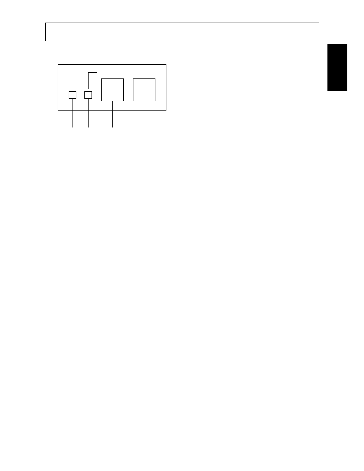
1 ON LINE switch
Switches the printer between ON
LINE and OFF LINE. ON LINE
and OFF LINE switching is possible only when paper is loaded in the
printer.
2 FEED switch
• When this switch is pressed and
then released within 0.5 sec., the
paper feeds on line.
• When this switch is held depressed
for more than 0.5 sec., the paper
feeds continuously.
(The above paper feed operation is
possible for both ON LINE and OFF
LINE modes.)
3 POWER lamp (green LED)
• Lights when the power to the printer is on.
• Flashes when paper is out, mechanical error occurs, when there is an alarm due
to head temperature detection, or when a CPU error has occurred.
• If the paper is out, load new paper and press the ON LINE switch.
• When the POWER lamp flashes due to occurrence of a mechanical error, turn
off the power and remove the cause of a mechanical error and then turn on the
power again to reset the printer.
• If the POWER lamp flashes due to the alarm of the head temperature detection,
the printer will be set automatically when the head temperature becomes low.
4 ON LINE lamp (green LED)
LED lit: Printer is ON LINE
LED off: Printer is OFF LINE
LED flashes: CPU error
When the POWER lamp and ON LINE lamp light simultaneously, a CPU
error has occurred.
ON LINEPOWER FEED
3 4 1 2
Fig. 5-1 Control panel
Page 20
– 17 –
ENGLISH
5-2. Switch Operation (Combined Switch Operation)
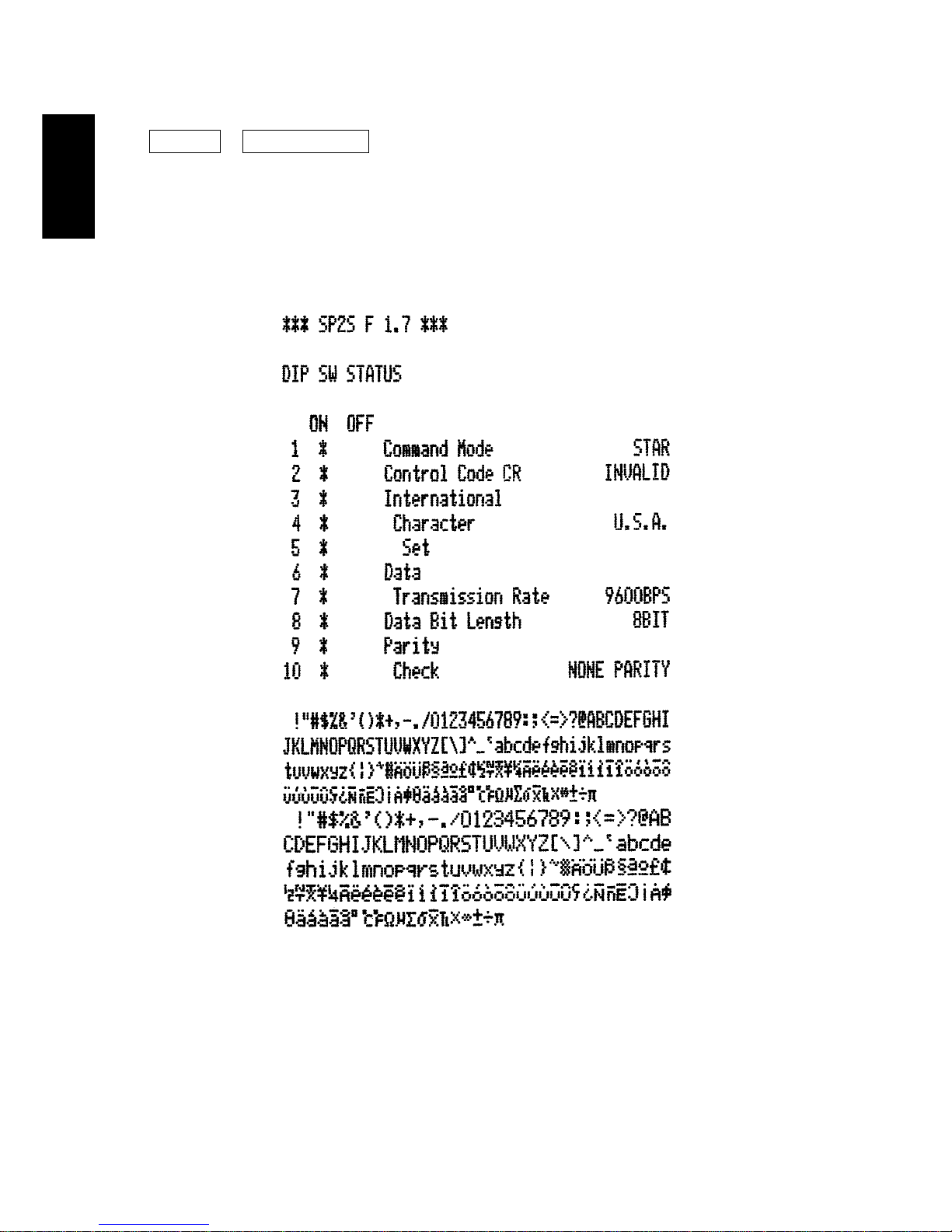
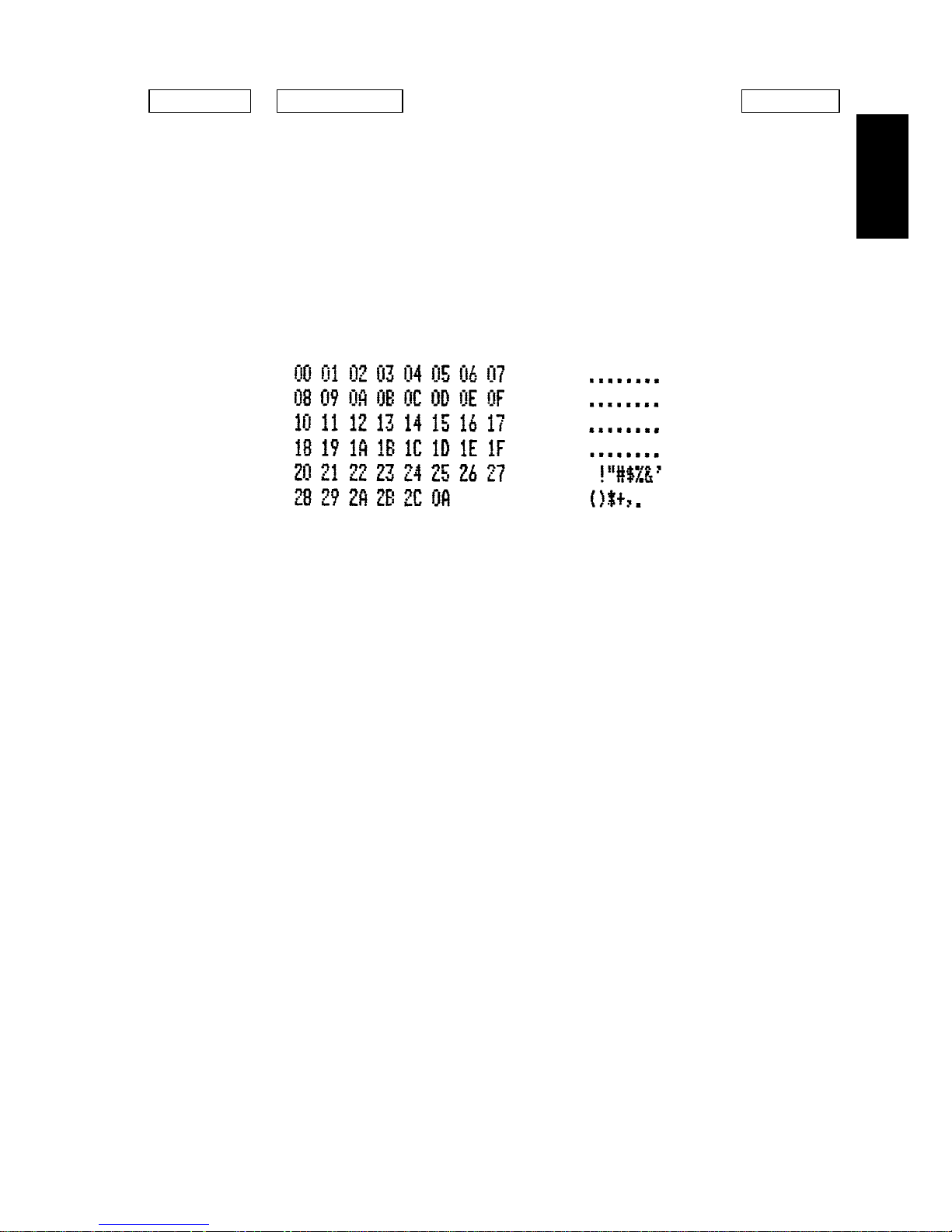
1 <SELF PRINTING>
FEED + POWER ON (Turn the power on while holding the FEED switch
depressed.)
Self-printing will be performed according to the VER. NO., DIP switch
settings and character order. When the FEED switch is held continuously or
when the FEED switch is depressed at the time of the end of self-printing, only
the characters will be printed out repeatedly.
Fig. 5-2 Self printing sample (when using serial interface printer)
Page 21
– 18 –
ENGLISH
2 <Hexadecimal dump mode>
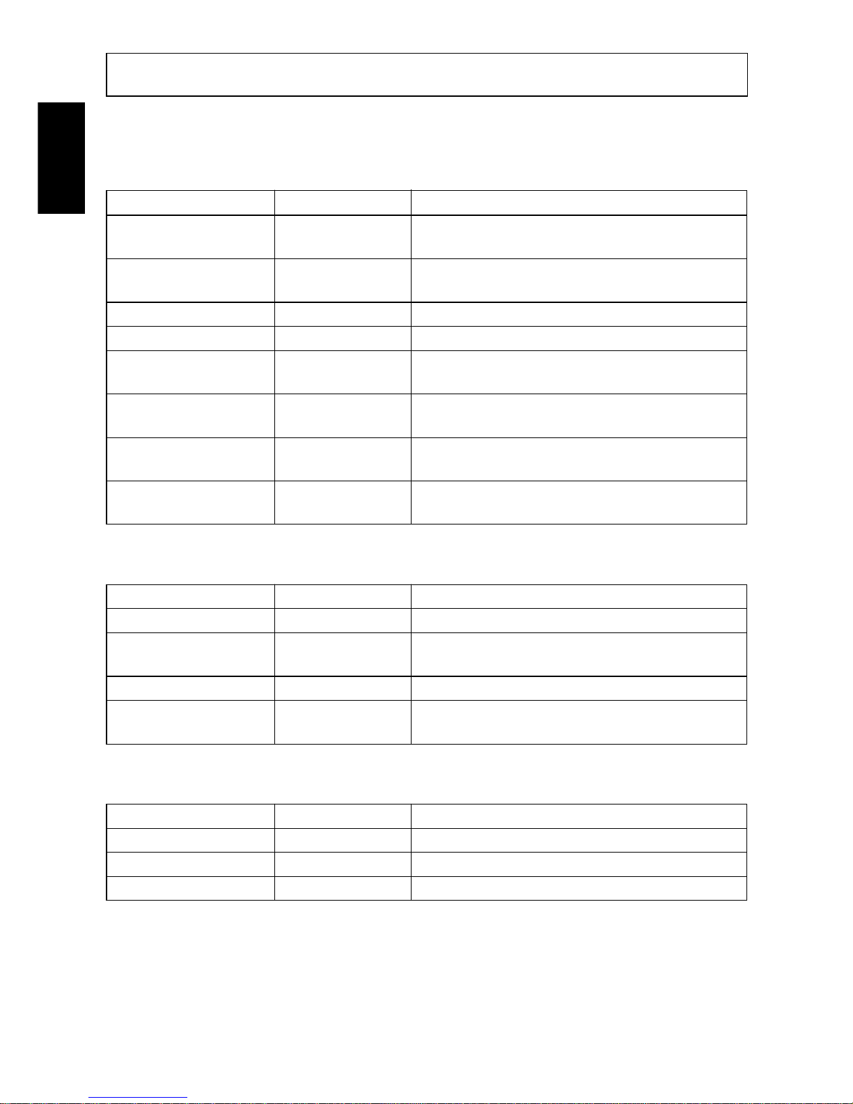
ON LINE + POWER ON (Turn the power on while holding the ON LINE
switch depressed.)
Each of the signals sent from the computer to the printer will be printed out in
hexadecimal code.
This function allows you to check if a control code sent to the printer by the
program being used is correct or not. The last line is not printed if its data is
less than one full line. However, if the ON LINE switch is pressed to set the
off line mode, the last line will be printed. To turn off the mode, it is necessary
to turn off the printer completely.
Fig. 5-3 Hexadecimal dump printing sample
Page 22
– 19 –
ENGLISH
6. Control Codes
STAR mode
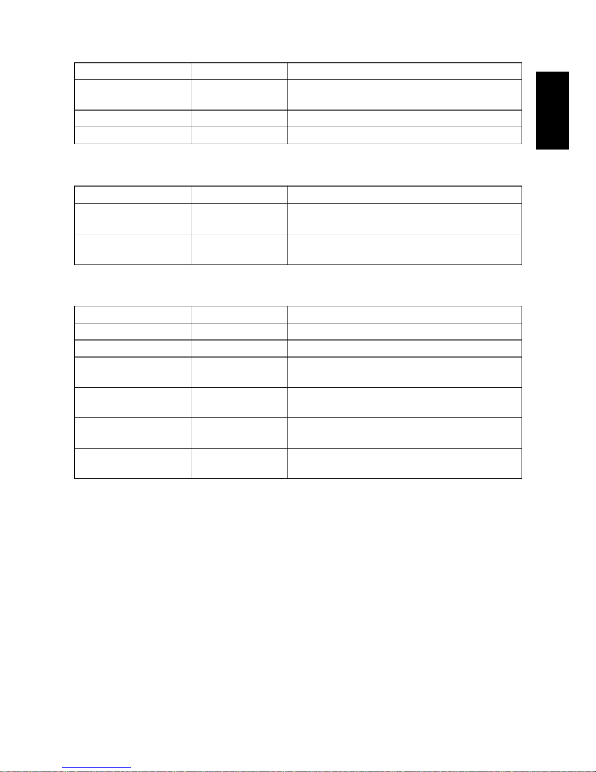
6-1. Control Codes Used in Character Setting
Control codes Hexadecimal codes Function
<ESC> “R” n 1B 52 n Select international character set. Default is accord-
ing to the dip switch settings 3, 4 and 5.
<ESC> “M” 1B 4D Select 7 × 7 (Half dots) character size (Default
setting)
<ESC> “P” 1B 50 Select 9 × 7 (Half dots) character size
<SO> 0E Select expanded character mode
<SI> 0F Cancel expanded character mode
(Default setting)
<DC4> 14 Cancel expanded character mode
(Default setting)
<ESC> “W” “1” 1B 57 31 Select expanded character mode
<ESC> “W” <1> 1B 57 01
<ESC> “W” “0” 1B 57 30 Cancel expanded character mode
<ESC> “W” <0> 1B 57 00 (Default setting)
6-2. Control Codes Used in Print Mode Setting
Control codes Hexadecimal codes Function
<ESC> “4” 1B 34 Red color print selection (enable for SP216)
<ESC> “5” 1B 35 Red color print deselection (enable for SP216) (De-
fault setting)
<ESC> “E” 1B 45 Emphasized print mode selection
<ESC> “F” 1B 46 Emphasized print mode deselection (Default set-
ting)
6-3. Control Codes Used in Line Spacing
Control codes Hexadecimal codes Function
<LF> 0A Line feed
<CR> 0D Line feed (same as LF)
<ESC> “a” n 1B 61 n Feed paper n lines
Page 23
– 20 –
ENGLISH
6-4. Control Codes Used for Peripheral Units
Control codes Hexadecimal codes Function
<ESC> <BEL> n1 n2 1B 07 n1 n2 Adjust drive pulse width for peripheral unit (Default
setting)
<BEL> 07 Deferred drive command “A” for peripheral unit 1
<FS> 1C Immediate drive command “B” for peripheral unit 1
6-5. Auto Cutter Control (SP240 type only)
Control codes Hexadecimal codes Function
<ESC> “d” “0” 1B 64 30 Full-cut command to the auto cutter
<ESC> “d” <0> 1B 64 00
<ESC> “d” “1” 1B 64 31 Partial-cut command to the auto cutter
<ESC> “d” <1> 1B 64 01
6-6. Other Control Codes
Control codes Hexadecimal codes Function
<CAN> 18 Cancel print data in buffer
<ESC> “@” 1B 40 Initialize printer
<ESC> “e” “0” 1B 65 30 ON LINE/FEED switch valid
<ESC> “e” <0> 1B 65 00 (Default setting)
<ESC> “e” “1” 1B 65 31 ON LINE/FEED switch invalid
<ESC> “e” <1> 1B 65 01
<ESC> “f” “0” 1B 66 30 ON LINE switch valid
<ESC> “f” <0> 1B 66 00 (Default setting)
<ESC> “f” “1” 1B 66 31 ON LINE switch invalid
<ESC> “f” <1> 1B 66 01
Page 24

– 21 –
ENGLISH
Page 25
– 87 –
APPENDIX
Appendix A: Serial Interface
14
113
25
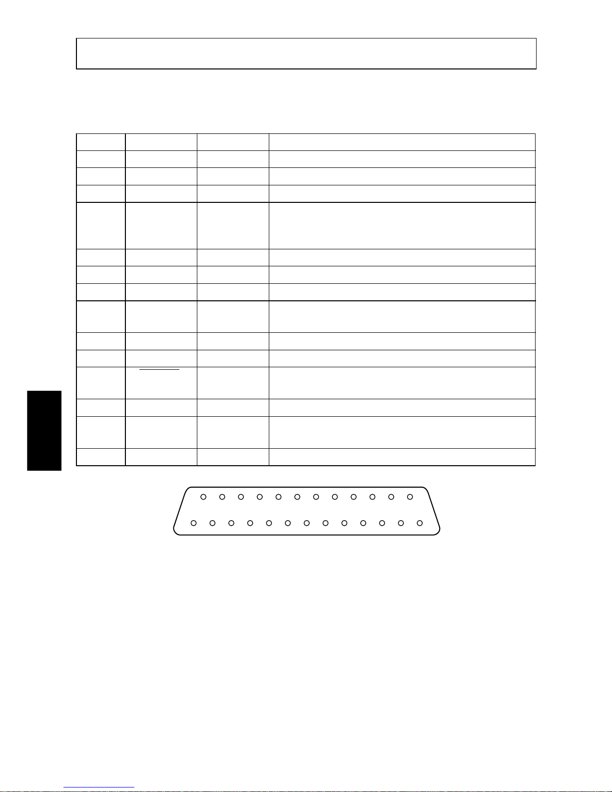
A-1. Connectors and Signals
RS-232C
Pin no. Signal name I/O direction Function
1 F-GND — Frame ground
2 N/C Not connected
3 RXD IN Received data
4 RTS OUT Data transmission request signal. This is always
“SPACE” when the printer is turned on. (Always
“SPACE” status)
5-6 N/C Not connected
7 S-GND — Signal ground
8-10 N/C Not connected
11 RCH OUT When the printer is ready to receive data, the signal line
is same as pin 20.
12 N/C Not connected
13 GND — Signal ground
14 FAULT OUT When printer error occurs (such as paper out, mechani-
cal error, etc.) this signal changes to “MARK”.
15-19 N/C Not connected
20 DTR OUT Data terminal ready signal. When the printer is ready to
receive data, this signal changes to “SPACE”.
21-25 N/C Not connected
Fig. A-1 Serial interface connector
Page 26
– 88 –
APPENDIX
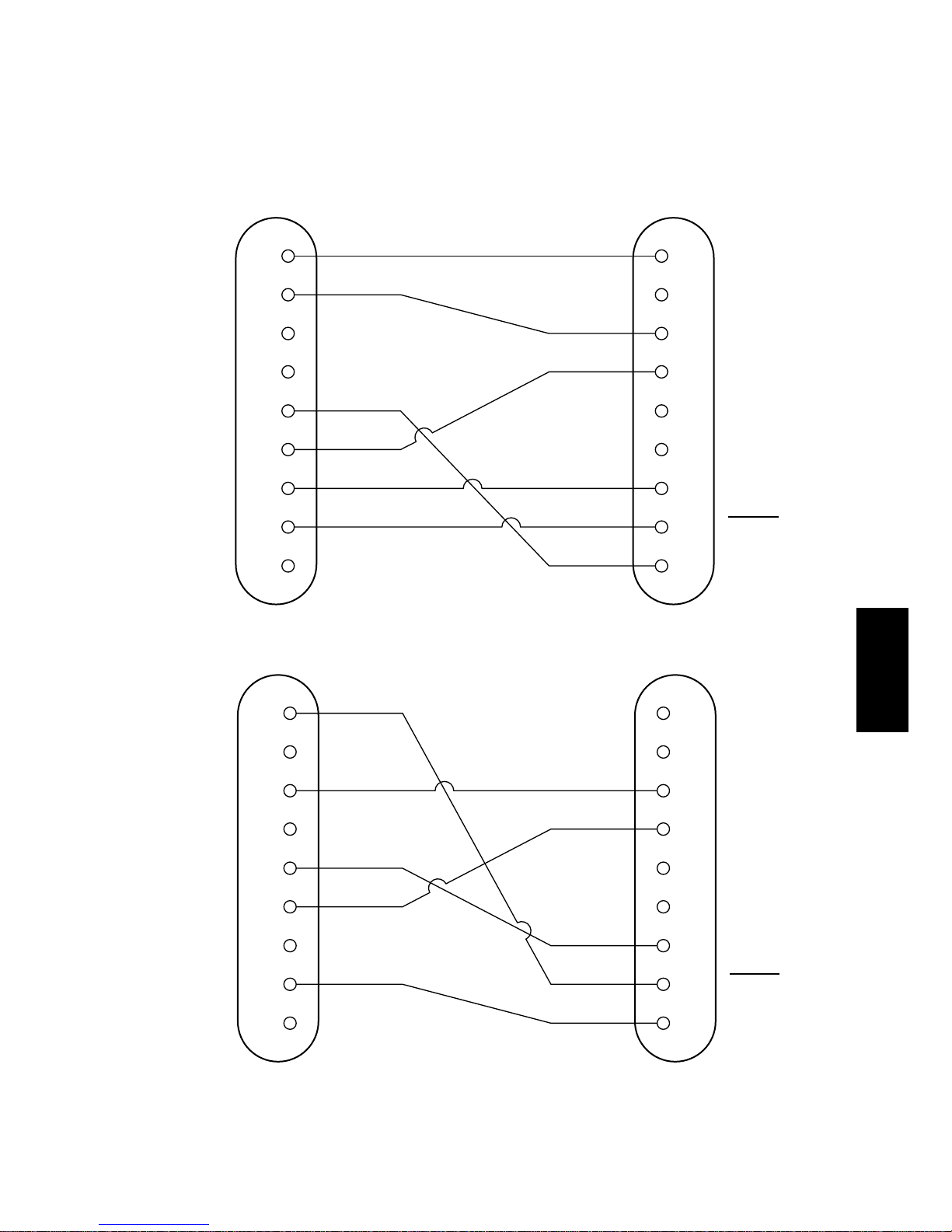
A-2. Interface Connections
The following is a basic example of interface connections. (For interface
connections, refer to the specifications for the respective interface.)
Fig. A-2 Example of interface connections
1 F-GND
N/C
RXD
RTS
N/C
N/C
S-GND
FAULT
DTR
F-GND
2TXD
3RXD
4RTS
5CTS
6DSR
7S-GND
8DCD
20
1
2
3
4
5
6
7
14
20DTR
Host computer
(D-sub 25 pin)
Printer side
(D-sub 25 pin)
1 F-GND
N/C
RXD
RTS
N/C
N/C
S-GND
FAULT
DTR
DCD
2RXD
3TXD
4DTR
5S-GND
6DSR
7RTS
8CTS
9
1
2
3
4
5
6
7
14
20RI
Host computer
(D-sub 9 pin)
Printer side
(D-sub 25 pin)
Page 27
– 89 –
APPENDIX
A-3. Dip Switch Setting
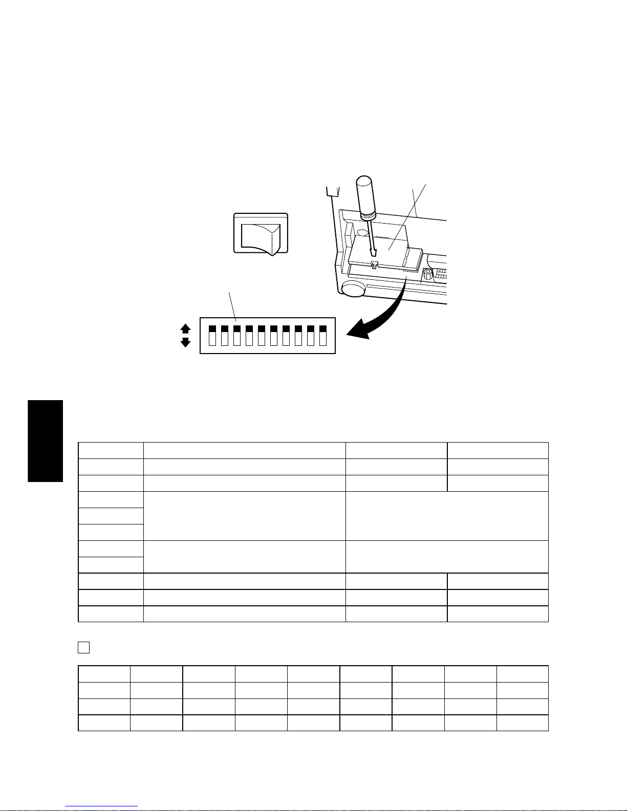
Each of the switches in the DIP switch array is factory preset to ON. Be sure to
turn the power to both the printer and host computer off before changing the
setting of the DIP switches.
The dip switch array will appear when the ROM cover is removed.
Fig. A-3 DIP switch array
■ DIP-SW Factory presetting: all on
Switch Function ON OFF
1 Command mode STAR mode VeriFone mode
2 Control code CR Invalid Valid
3
4 International character set Refer to the following.
5
6
Data transmission rate Refer to the following.
7
8 Data bit 8-data bit 7-data bit
9 Parity check No Yes
10 Parity Odd Even
International character set
Switch U.S.A. France Germany England Denmark Sweden Italy Spain
3 ON OFF ON OFF ON OFF ON OFF
4 ON ON OFF OFF ON ON OFF OFF
5 ON ON ON ON OFF OFF OFF OFF
101
ON
OFF
DIP switch
Power off
ROM cover
Page 28
– 90 –
APPENDIX
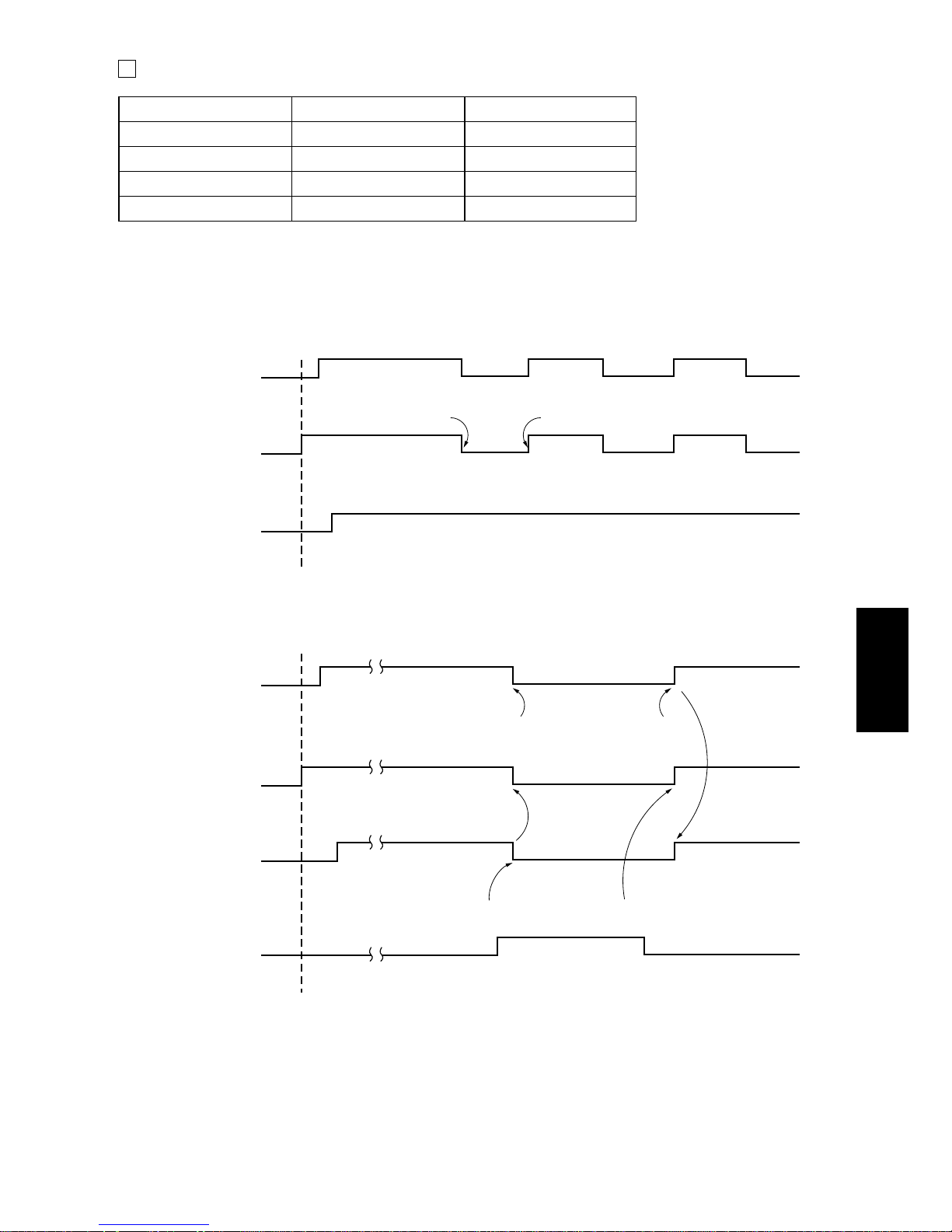
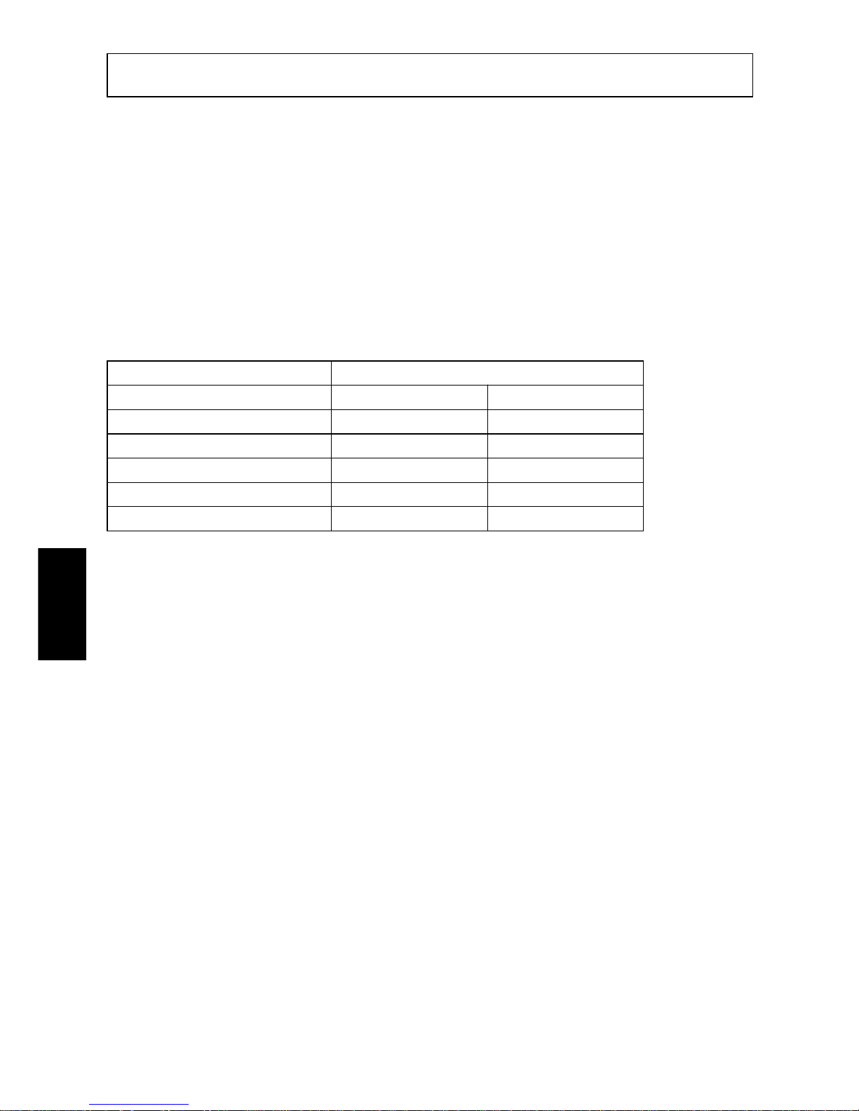
Data transmission rate (baud rate)
Baud rate Switch 6 Switch 7
1200 OFF OFF
2400 OFF ON
4800 ON OFF
9600 ON ON
A-4. Communication Protcol
Signals are controlled using the DTR line as BUSY flag.
If printer errors do not occur after the power is turned on, the DTR signal line
changes to “SPACE”.
When the host computer confirms that the DTR signal line is set to “SPACE”, the
host computer sends the data text via the RXD signal line to the printer. Also, the
printer will set the DTR signal line to “MARK” when the empty space in the data
RXD
DTR
Printing
Data
Data Data
Buffer full Buffer empty
Power on
when paper is out
RXD
DTR
OFF LINE ON LINE
When printing
PAPER OUT
signal
Power on
Paper end
Press the ONLINE button
after loading paper.
Page 29
– 91 –
APPENDIX
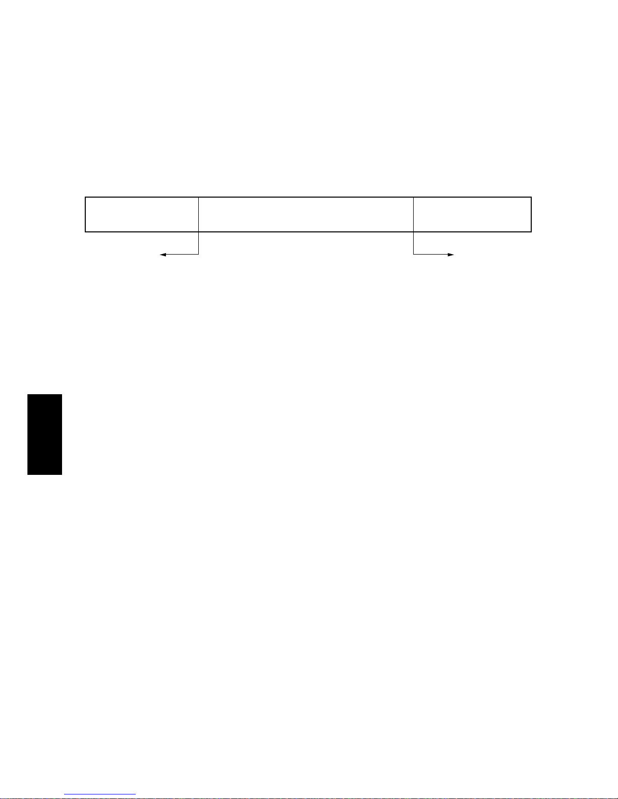
buffer is below 256 bytes. After the host computer detects that the DTR signal line
is at “MARK”, transmission of the data text is stopped. In this instance, data can
still be received up until the data buffer becomes completely full.
When the empty space in the data buffer is increased by following printing (when
the data in the data buffer is reduced to 256 bytes or less), the printer sets the DTR
signal line to “SPACE”.
[Paper out]
When the “paper out” detector senses the end of the paper, the printer stops
printing after printing or feeding a maximum of two more lines on the paper.
Immediately after a “paper out” condition is detected, the printer sets to OFF
LINE and the DTR changes to “MARK”. (To reset printer after a “paper out”,
load paper into the printer and press the ON LINE switch to set the printer to ON
LINE.)
[Mechanical error]
Mechanical errors are detected when the motor locks and the unit will not print.
Immediately after a mechanical error occurs, the printer sets the DTR to
“MARK” and then sets the printer to OFF LINE. To cancel a mechanical error,
turn the power to the printer off and remove the cause of the error then turn the
power on again to reset the printer.
[Framing error]
A framing error occurs when “SPACE” is detected at the stop bit. When a framing
error or a vertical parity error occurs for the data which is received, the printer
prints out a “?” mark to indicate that the error occurred.
Data buffer
Full Near Full
Empty area
256 bytes
DTR"MARK"
Near Empty Empty
Reception data
256 bytes
DTR"SPACE"
Page 30
– 92 –
APPENDIX
Appendix B: Parallel Interface
B-1. Interface Specifications
The operating specifications of the parallel interface are as follows.
(1) Data transfer rate : 1000 to 6000 characters per second
(2) Synchronization : Via externally supplied STROBE pulses
(3) Handshaking : ACK and BUSY signals
(4) Logic level : Compatible with TTL level
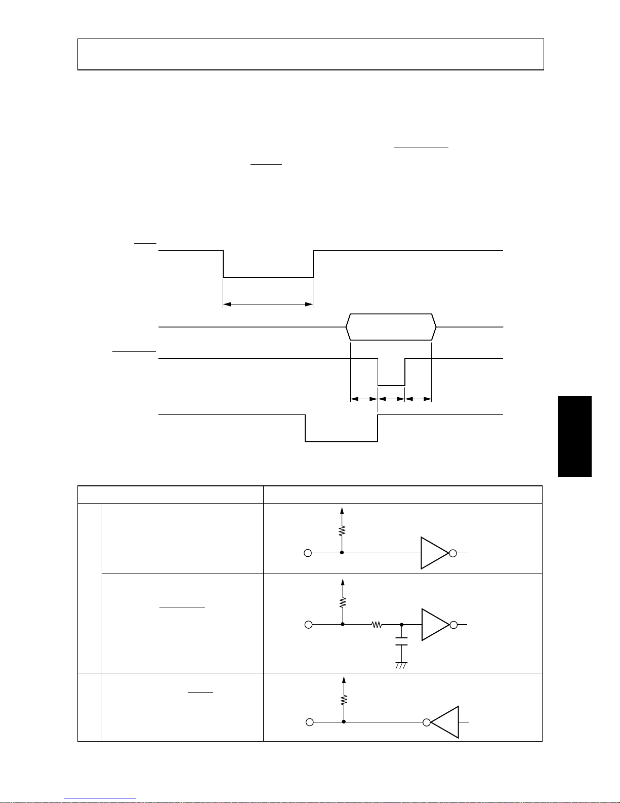
B-2. Interface Timing
Fig. B-1 Interface timing diagram
Signal Name Circuit Example
DATA 1-DATA 8
(To Printer)
STROBE
(To Printer)
BUSY, ACK
(From Printer)
Fig. B-2 Typical interface circuit
ACK
Approx.9 µs
Data
STROBE
BUSY
TTT
T:more than 0.5 µs
74HC Compatible
4.7KΩ
100Ω
470pF
74HC Compatible
1KΩ
1.8KΩ
74LS Compatible
INPUTOUTPUT
Page 31
– 93 –
APPENDIX
B-3. Connectors and Signals
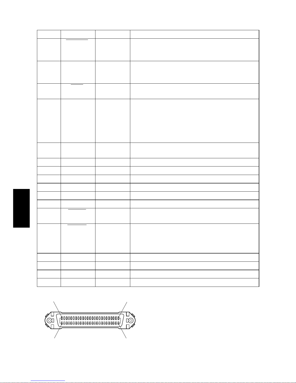
Pin No. Signal Name IN/OUT Function
1 STROBE IN Signals when data is ready to be read. Signal goes from
HIGH to LOW (for at least 0.5 microsec.) when data is
available.
2-9 DATA1-8 IN These signals provide the information of the first to
eighth bits of parallel data. Each signal is at HIGH level
for a logical 1 and at a LOW level for a logical 0.
10 ACK OUT A 9 microsecond LOW pulse acknowledges receipt of
data.
11 BUSY OUT When this signal goes LOW, the printer is ready to
accept data. When the printer is in one of the conditions
below. “HIGH” is set.
1. Data being entered.
2. Off line.
3. Error condition.
12 PAPER OUT OUT This signal is normally LOW. It will go HIGH if the
printer runs out of paper.
13 SELECTED OUT This signal is HIGH when the printer is online.
14-15 N/C Not connected
16
SIGNAL GND
Signal ground.
17
CHASSIS GND
Chassis ground, isolated from logic ground.
18 +5VDC +5VDC (Max 50 mA)
19-30 GND Twisted pair return signal ground level.
31 RESET IN When this signal goes LOW, the printer is reset to its
power-on condition.
32 ERROR OUT This signal is normally HIGH. This signal goes LOW
to signal that the printer cannot print due to an error
condition.
Refer to Item 8-4 Emergency Suspension.
33 EXT GND External ground.
34 OUT1 OUT Unused.
35 N/C Not connected
36 The printer side is always set to HIGH.
This connector mates with an
Amphenol 57-30360 connector
Fig. B-3. Parallel interface connector (printer side)
(19) (36)
(1) (18)
Page 32
– 94 –
APPENDIX
B-4. Dip Switch Setting
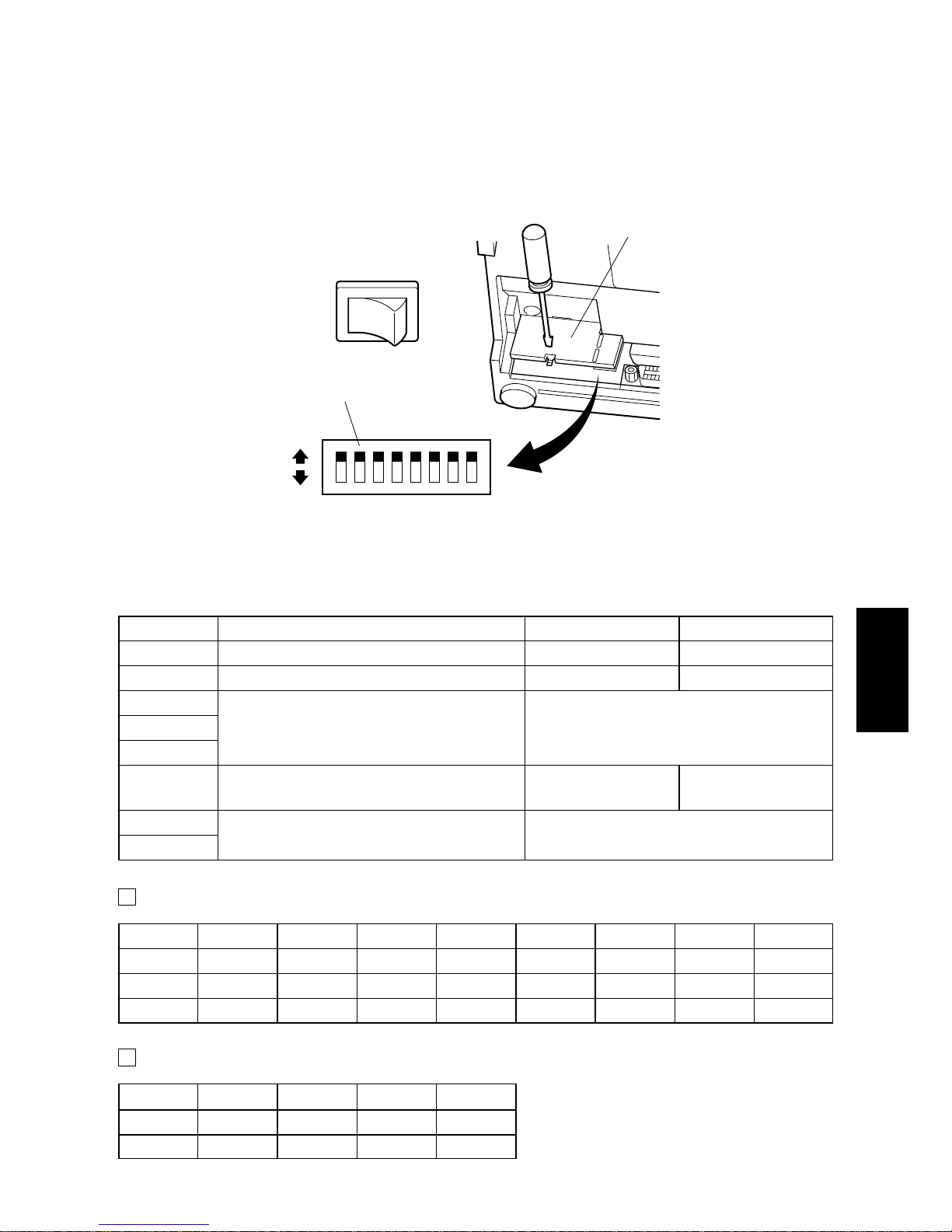
Each of the switches in the DIP switch array is factory preset to ON. Be sure to
turn the power to both the printer and host computer off before changing the
setting of the DIP switches.
The dip switch array will appear when
the ROM cover is removed.
Fig. B-4 DIP switch array
■ DIP-SW Factory presetting: all on
SW Function ON OFF
1 Paper out detection Valid Invalid
2 Control code CR Invalid Valid
3
4 International character set See below
5
6
Data buffer
Available Unavailable
(approx. 1k byte) (1 line)
7
Character generation setting See below
8
International character set
Switch U.S.A. France Germany England Denmark Sweden Italy Spain
3 ON OFF ON OFF ON OFF ON OFF
4 ON ON OFF OFF ON ON OFF OFF
5 ON ON ON ON OFF OFF OFF OFF
Character generation
SW US EC JP JP
7 ON ON OFF OFF
8 ON OFF ON OFF
81
ON
OFF
DIP switch
Power off
ROM cover
Page 33
– 95 –
APPENDIX
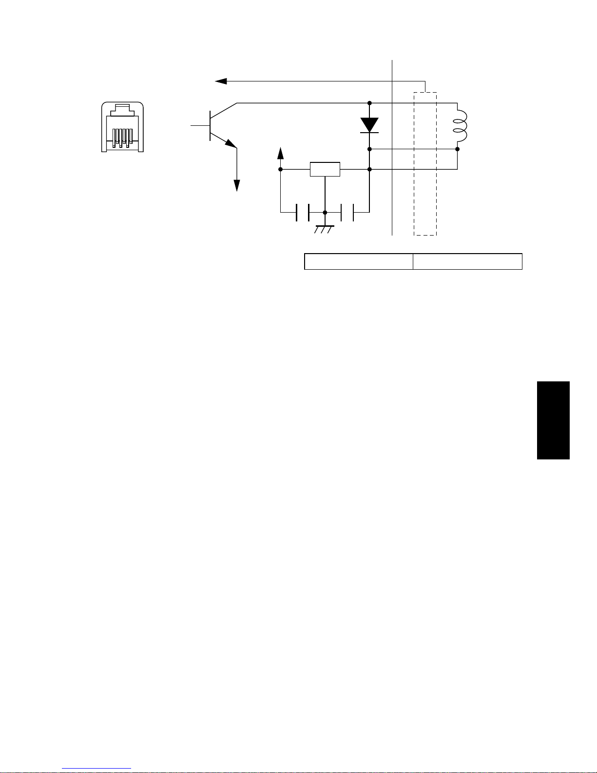
Appendix C: Peripheral Unit Drive Circuit
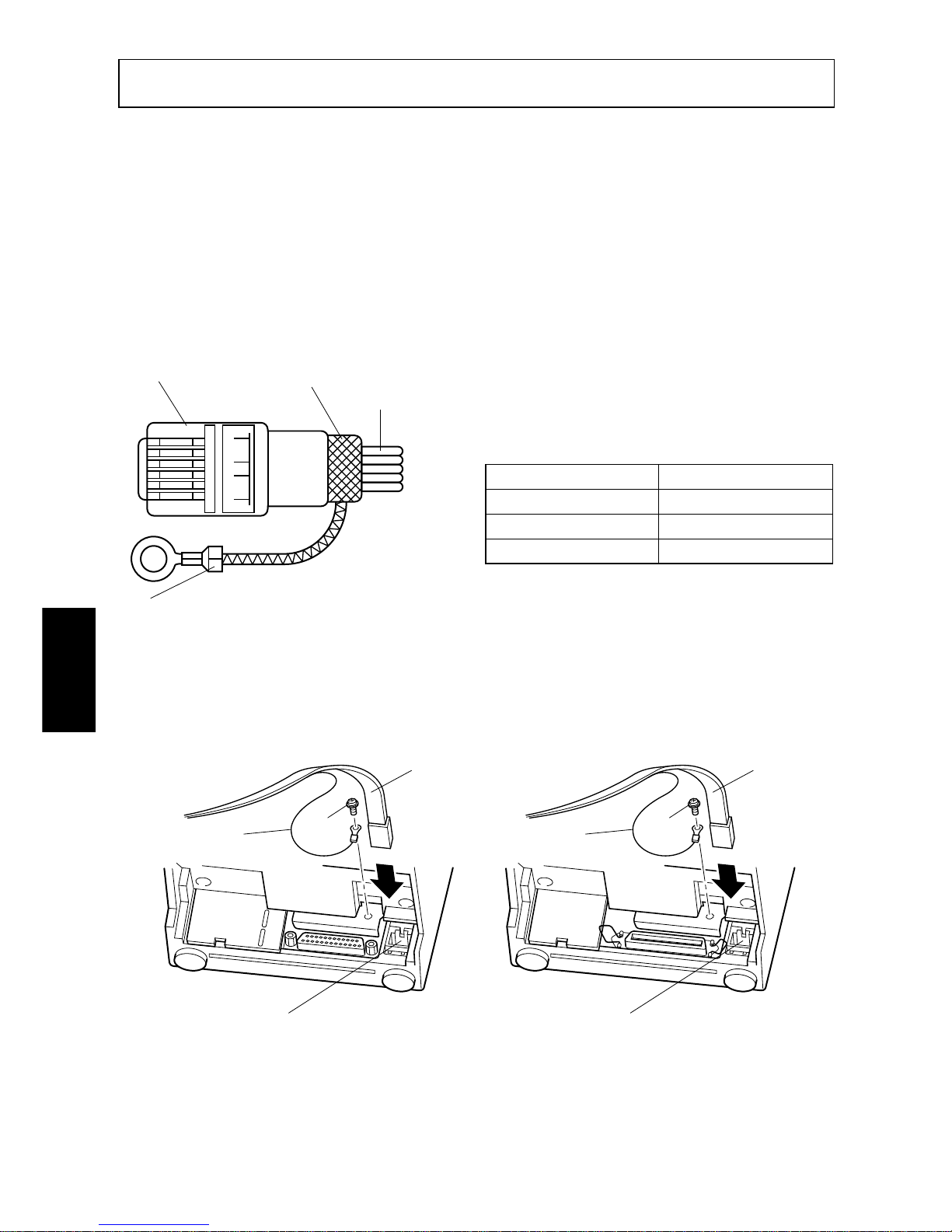
A drive circuit for driving peripheral units (such as cash drawers) is featured on
the main logic board of this printer. A modular connector for driving peripheral
unit is featured on the output side on the drive circuit. When using this circuit,
connect the cable for the peripheral unit. (Cables must be prepared by the user.)
Note: Peripheral unit drive circuit connector only connects to peripheral units
such as cash drawers, etc.
Do not connect it to a telephone.
Use cables which meet the following specifications.
Note: Pin 1 must be shield drain wire connected to
peripheral device frame ground.
Fig. C-1 Cable specifications
1 Connecting the cable
SERIAL INTERFACE PARALLEL INTERFACE
Separated ground wire is required for Europe only.
Fig. C-2 Connecting the cable
16
Modular plug
Wire lead
Separated Ground wire
connected to shield
(Europe only).
Shield
Manufacturer Model
MOLEX 90075-0007
AMP 641337
JAPAN BURNDY B-66-4
Cable
Separated
Ground wire
Connector for the
peripheral unit drive circuit
Screw
M3x5
Cable
Separated
Ground wire
Connector for the
peripheral unit drive circuit
Screw
M3x5
Page 34
– 96 –
APPENDIX
2 Drive circuit
Fig. C-3 Drive circuit
Drive output 24V, max. 1.0 A
1 With shield
Cash
drawer
TR: D2010
2
LD
VH
7824
TR
M-GND
F.G.
3
4
6
6-P modular jack
connector
1
Page 35
– 97 –
APPENDIX
Appendix D: General Specifications
Printing method: Serial impact dot matrix
Print direction: Bi-directional
Number of head pins: 7 wires
Number of print columns: 42 columns, 16 CPI
Character set: ASCII 96 (characters)
Special characters 64
IBM special characters 83
International characters12
Font configuration 7 (Half dots) × 7 or 9 (Half dots) × 7
Paper width 3.0 inch (76 mm)
CPI 16 13.4
Number of columns 42 35
Column spacing (mm) 1.58 1.90
Character size (mm) 1.28 × 2.87 1.59 × 2.87
Dot space (H × V mm) 0.316 × 0.423 0.316 × 0.423
Print area (mm) 66.0 66.0
Print speed: Approx. 2.5 lines per sec.
Line spacing: 1/6-inch
Paper feed method: Friction feed
Paper feed speed: Approx. 9 lines/sec.
Paper specifications
Paper type: Ordinary bond and carbonless copy paper
Paper width: 76±0.5 mm (3.0 inches)
Roll diameter: 85mm (3.35 inches) max.
Thickness (single) 0.07 mm to 0.10 mm
(copies) Original + 2 copies (Max. 0.2 mm)
Internal diameter of roll: 12±1 mm
Note: The paper must not be glued to the core.
Paper cutter reliability 300,000 cut (MCBF)
(SP240 type only)
Ink ribbon specifications
Ribbon type: Cartridge cassette
Color: SP212/242 type: Single color (Purple or black)
SP216/246 type: Two color (Black and red)
Ribbon material: Nylon 66 (#40 denier)
Page 36

– 98 –
APPENDIX
Ribbon life: Single color:
Purple 3,000,000 characters
Black 1,200,000 characters
Two color:
Black on two color 600,000 characters
Red on two color 300,000 characters
Interface
Serial interface: RS232C serial interface
Parallel interface: Centronics compatible
Data buffer: Approx. 1K
Peripheral unit drive circuit: 1 circuits (24V, max. 1A)
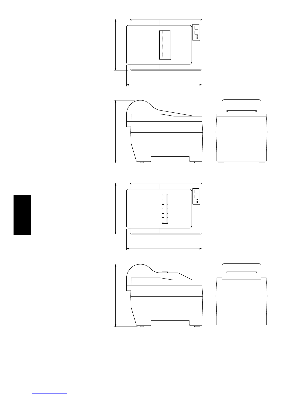
Overall dimensions: SP210 type: 158W × 234 D × 193H (mm)
SP240 type: 158W × 240 D × 193H (mm)
Weight: SP210 type: Approx. 3.0kg
SP240 type: Approx. 3.4kg
Power Supply: 120VAC ±10% 0.3A 60Hz
230 VAC + 6, –10% 0.2A 50/60Hz
240VAC ±10% 24W 50Hz
AC power cable: Approx. 180 cm long
Power consumption: Max. 24 W Avg. 19W (During continuous
printing of ASCII characters)
Ambient temperature/humidity
Operating temperature: 0°C to +50°C
Operating humidity: 10% to 90% RH (without condensation)
Storage temperature: –20°C to +70°C
Storage humidity: 5% to 95%RH (at 40°C, without condensa-
tion)
Mechanism reliability: 2,500,000 lines MCBF (except head life and
auto cutter)
Print head life: 75 million characters
Accessory This printer has no optional accessory.
Page 37
– 99 –
APPENDIX
234
158193
240
158193
SP210 Type
SP240 Type
Fig. D-1 Overall dimensions (mm)
Page 38
– 100 –
APPENDIX
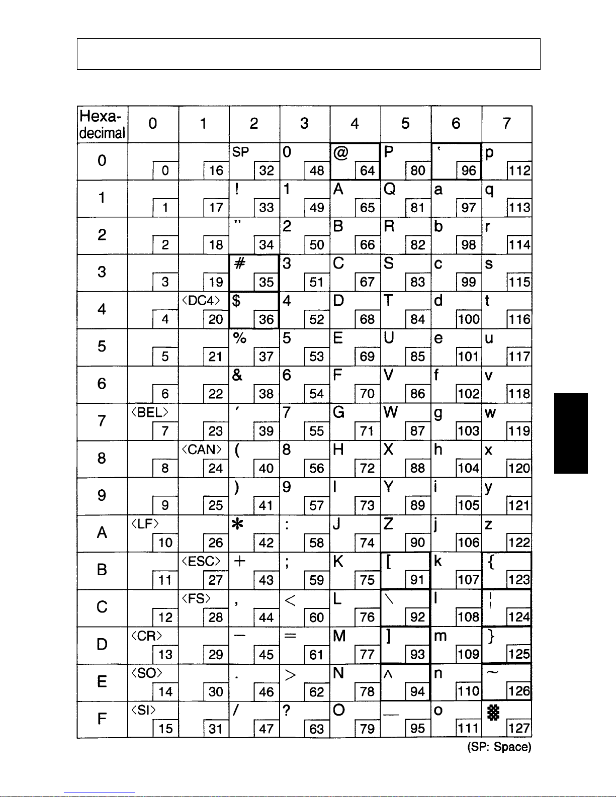
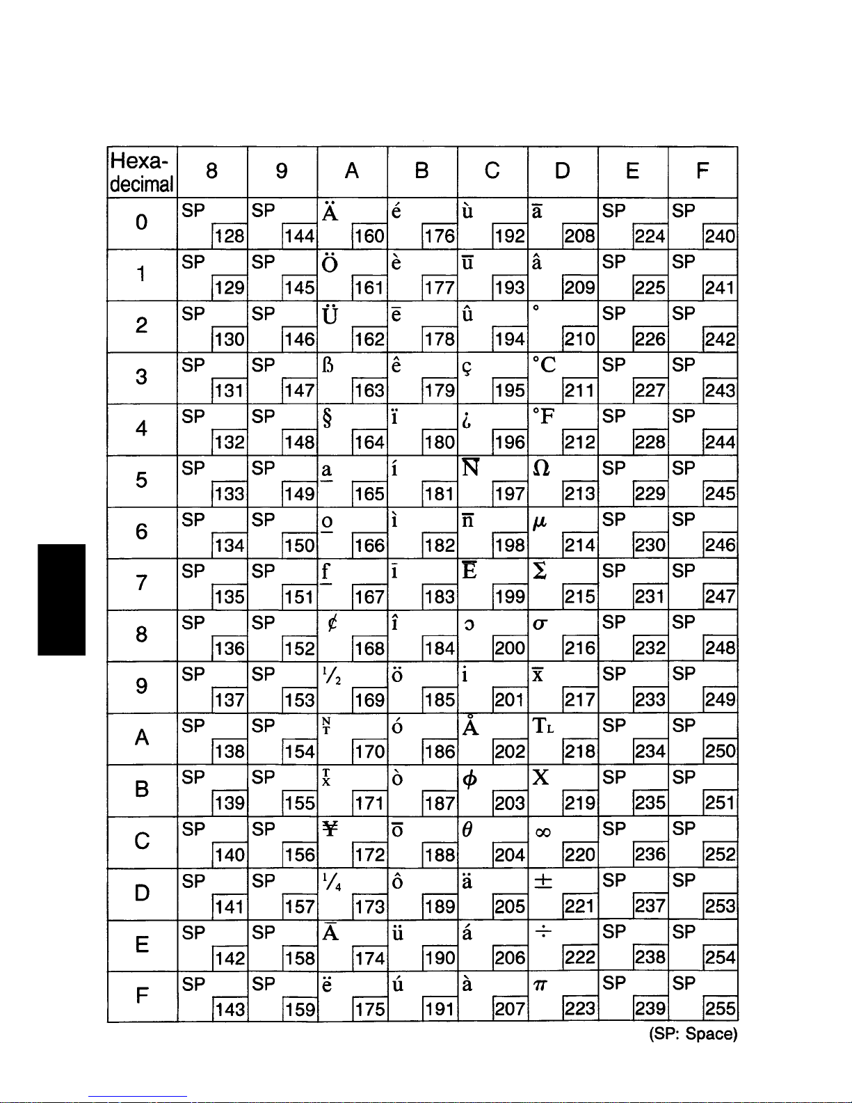
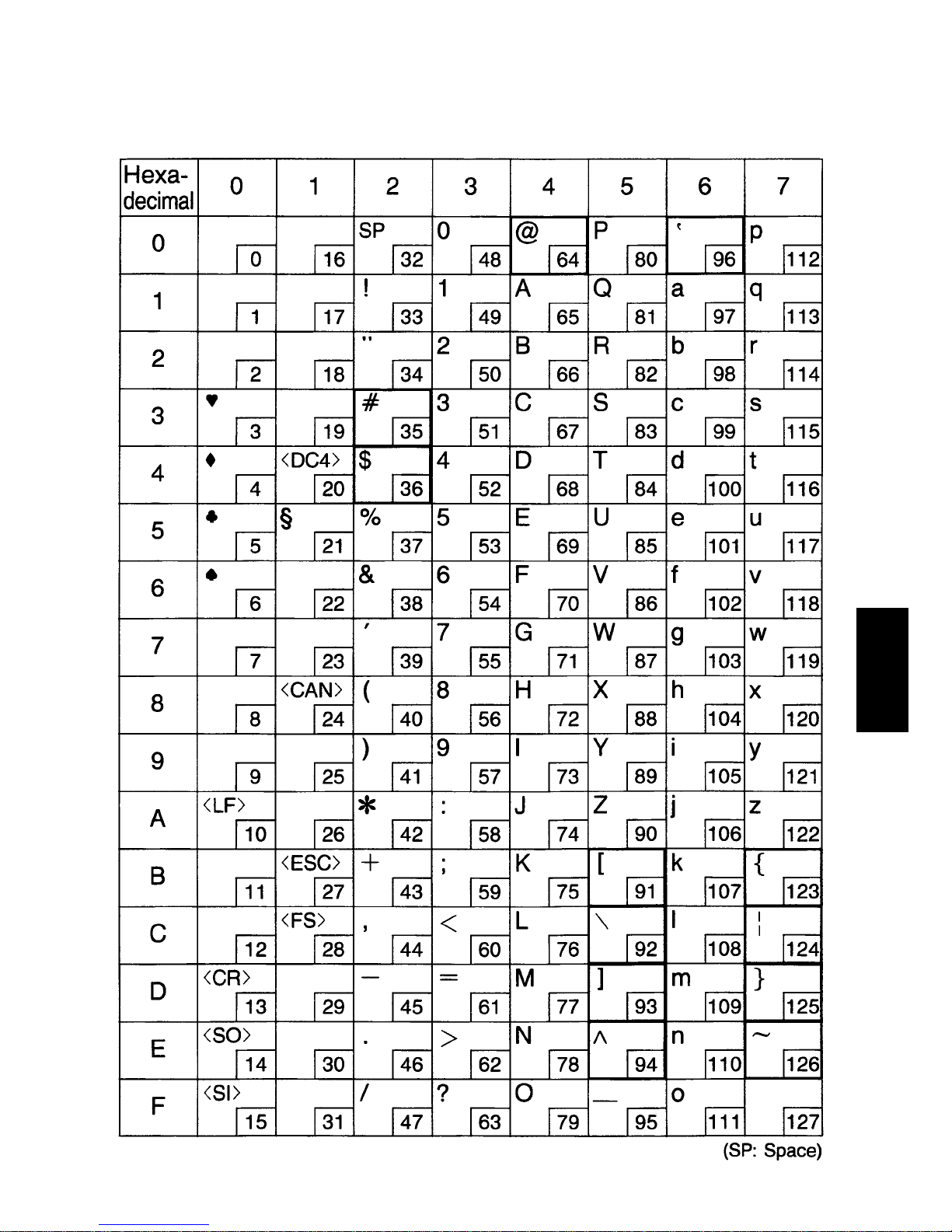
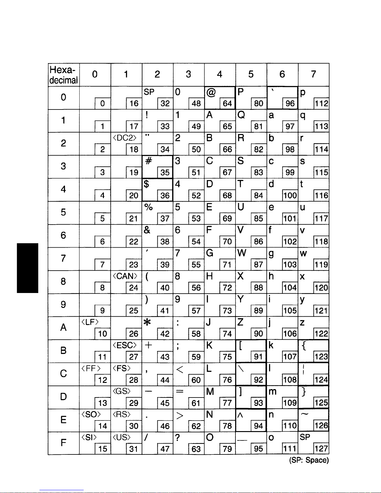
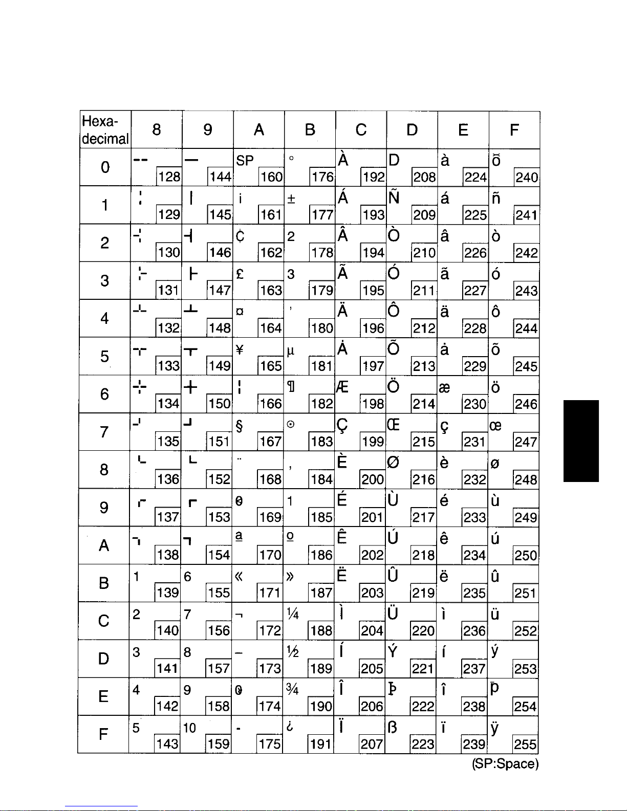
Appendix E: Character Font Table
E-1. U.S.A.
Page 39
– 101 –
APPENDIX
Page 40
– 102 –
APPENDIX
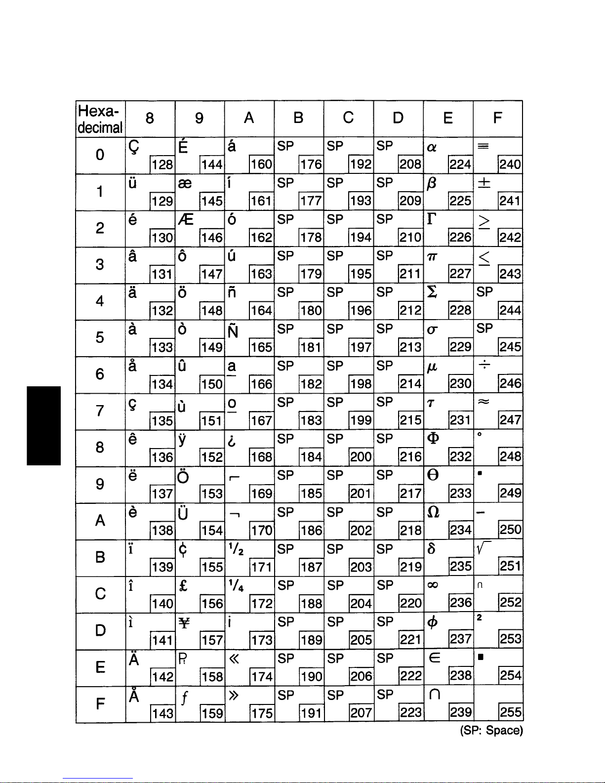
E-2. Europe
Page 41
– 103 –
APPENDIX
Page 42
– 104 –
APPENDIX
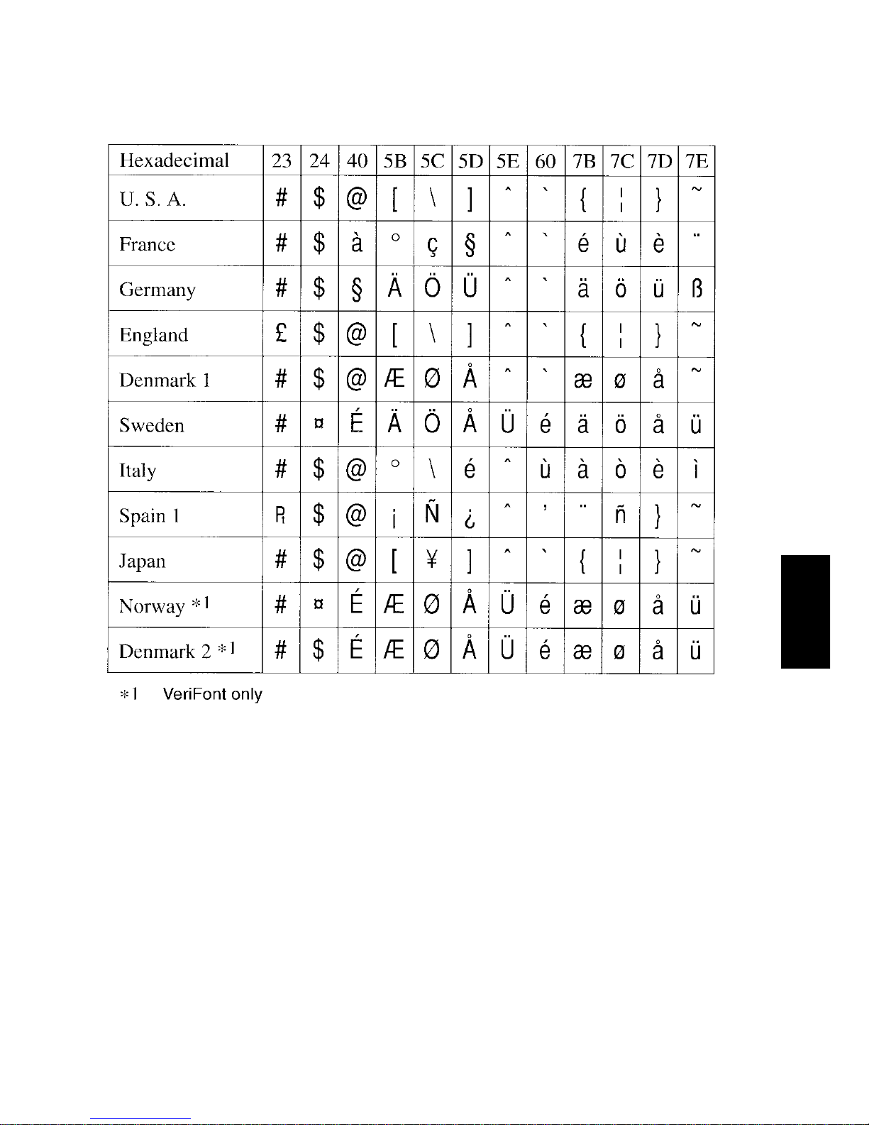
E-3. International Character Sets
Page 43
– 105 –
APPENDIX
E-4. VeriFont
Page 44
– 106 –
APPENDIX
Page 45

ELECTRONIC PRODUCTS DIVISION
STAR MICRONICS CO., LTD.
536 Nanatsushinnya, Shimizu, Shizuoka,
424-0066 Japan
Tel: 0543-47-0112, Fax: 0543-48-5271
Please access the following URL
http://www.star-micronics.co.jp/service/sp_sup_e.htm
for the lastest revision of the manual.
OVERSEAS SUBSIDIARY COMPANIES
STAR MICRONICS AMERICA, INC.
70-D Ethel Road West, Piscataway, NJ 08854 U.S.A
Tel: 732-572-9512, Fax: 732-572-5095
STAR MICRONICS U.K. LTD.
Star House, Peregrine Business Park, Gomm Road,
High Wycombe, Bucks, HP13 7DL, U.K.
Tel: 01494-471111, Fax: 01494-473333
1998.01.13
Printed in Japan, 80870055
 Loading...