

Page 1

Starjet SJ-48
TECHNICAL MANUAL
[ SECOND EDITION ]
Page 2

NOTICE
• All rights reserved. Reproduction of any part of this manual in any
form whatsoever, without STAR’s express permission is forbidden.
• The contents of this manual are subject to change without notice.
• All efforts have been made to ensure the accuracy of the contents
of this manual at the time of going to press. However, should any
errors be detected, STAR would greatly appreciate being informed of them.
• The above notwithstanding, STAR can assume no responsibility
for any errors in this manual.
© Copyright 1996 Star Micronics Co.,Ltd.
Page 3

INTRODUCTION
This manual is an introduction to ink jet printer SJ-48.
It is intended for use as a reference for maintenance procedures.
This manual is prepared for use at a technical level and not for the general user.
• This manual is divided into the following sections:
Chapter 1 General Specifications
Chapter 2 Theory of Operation
Chapter 3 Adjustments
Chapter 4 Parts Replacement
Chapter 5 Precautions and Maintenance
Chapter 6 Troubleshooting
Chapter 7 Parts List
• First edition : Oct.1991
Second edition: Oct.1992
1
2
3
4
5
6
7
Page 4

GENERAL SPECIFICATIONS
– 2 –
Page 5

CHAPTER 1
GENERAL SPECIFICATIONS
1. General Specifications..........................................................................................3
2. External Appearance and Composition ..............................................................6
3. DIP Switch Settings...............................................................................................7
4. Parallel Interface....................................................................................................8
4-1. General Specifications ........................................................................................... 8
4-2. Connector Signals .................................................................................................. 8
1
Page 6

GENERAL SPECIFICATIONS
– 2 –
Page 7
GENERAL SPECIFICATIONS
1. General Specifications
Printing system Serial Ink Jet Dot-matrix
Printing speed High Quality mode Economy mode
Pica 83 cps 83 cps
Elite 100 cps 100 cps
Semi-condensed 124 cps 124 cps
Condensed pica 142 cps 142 cps
Condensed elite 166 cps 166 cps
Print direction Bi-directional, logic-seeking
Uni-directional, logic-seeking (selectable)
Print head 48 nozzles
Life: 700,000 characters
Line spacing 1/6, 1/8, n/60, n/72, n/180, n/216, n/360
Font styles Roman and H-Gothic
Characters ASCII 96
International 16 sets(*)
IBM special 111
IBM block graphic 50
IBM code page 6 sets (**)
Download 128
* USA, France, Germany, England, Denmark I, Sweden, Italy, Spain I, Japan, Norway, Denmark II, Spain II,
Latin America, Korea, Irish, Legal
** #437 (U.S.A.), #850 (Multi-Lingual), #860 (Portuguese), #861 (Icelandic), #863 (Canadian French), #865 (Nordic)
Number of columns CPI Normal type
Pica 10 80
Elite 12 96
Semi-condensed 15 120
Condensed pica 17 137
Condensed elite 20 160
Proportional Variable
Character matrix High Quality Economy
Pica 48 × 36 24 × 36
Elite 48 × 30 24 × 30
Semi-condensed 32 × 24 16 × 24
Condensed pica 48 × 21 24 × 21
Condensed elite 48 × 18 24 × 18
Proportional 48 × n 24 × n
Bit image dot-matrix. DPI 8-bit 24-bit 48-bit
Normal-density 60 8 × 480 24 × 480 48 × 480
CRT graphics mode I 80 8 × 640 (Not supplied) (Not supplied)
CRT graphics mode II 90 8 × 720 24 × 720 48 × 720
Double-density 120 8 × 960 24 × 960 48 × 960
Triple-density 180(Not supplied) 24 × 1440 48 × 1440
Quadruple-density 240 8 × 1920 (Not supplied) Not supplied)
Hex-density 360(Not supplied) 24 × 2880 48 × 2880
– 3 –
Page 8

GENERAL SPECIFICATIONS
Paper feed Friction roller feed
Friction flat feed
Paper feed speed 5/6 inches/second max
Paper specifications
Width 7.2" ~ 8.5" (182 ~ 216 mm)
Length 7.2" ~ 14" (182 ~ 356 mm)
Weight 52 ~ 105 g/m
Envelope Commercial 10 only
Maximum buffer size Without Download 28 kB
With Download 4 kB
Emulations Standard mode: Epson LQ-860, NEC 24-wire Graphics command
IBM mode: IBM Proprinter X24E
Interface Centronics parallel
Ink Cartridge
Type Single cartridge ink supply (SC-10)
Ink Color Black only
Ink amount 28 g (0.9 oz)
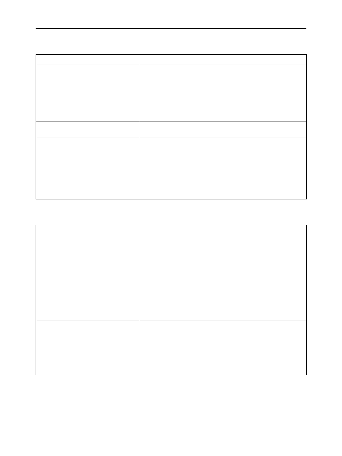
Dimensions and Weight
Width 310 mm (12.2")
Depth 216.5 mm (8.5")
Height 47.5 mm (1.9")
Weight 1.8 kg (4.0 lb)
AC adapter power supply 120 VAC, 220 VAC, 240 VAC, 50/60 Hz
(varies according to the country of purchase)
Options Battery pack (BP-10)
Automatic Sheet Feeder (SF-10CA)
2
– 4 –
Page 9
GENERAL SPECIFICATIONS
Fig. 1-1 External Dimensions
– 5 –
Page 10
GENERAL SPECIFICATIONS
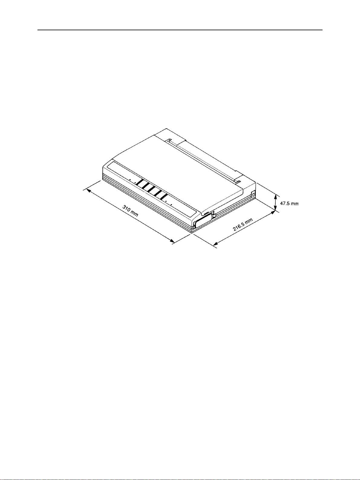
2. External Appearance and Composition
Fig. 1-2 Front View of the Printer
Fig. 1-3 Diagram of Internal Composition
– 6 –
Page 11
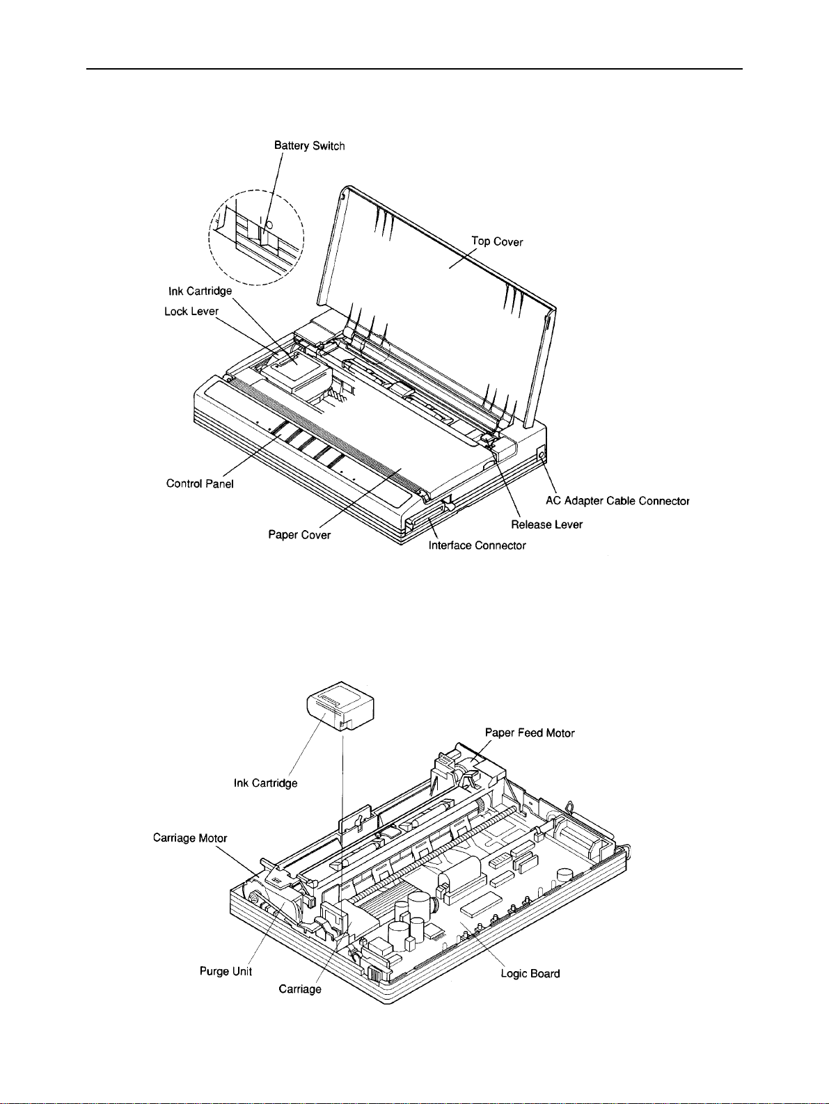
3. DIP Switch Settings
Switch Function ON OFF
1 Emulation Standard IBM
2 RAM usage Buffer Download
3 Auto LF with CR Disabled Enabled
4 Automatic Sheet Feeder Inactive Active
5 Font style Roman H-Gothic
6 Print mode Normal size Quarter size
7
8 International Character Set (See table below)
9or
10 IBM Code Page (See table below)
Character set
(Standard mode)
Character set
Fig. 1-4 DIP Switch Settings
Graphics Italics
(IBM) mode
Set #2 Set #1
GENERAL SPECIFICATIONS
All switches are set ON when the printer leaves the factory.
International Character Set (In the standard italics character set)
Country 8 9 10 Country 8 9 10
U.S.A. ON ON ON Denmark I ON O N OFF
France OFF ON ON Sweden OFF ON OFF
Germany ON OFF ON Italy ON OFF OFF
England OFF OFF ON Spain I OFF OFF OFF
IBM Code Page (Except in the standard italics character set)
Code Page 8 9 10 Code Page 8 9 10
#437 U.S.A. ON ON ON #863 Canadian French ON ON OFF
#850 Multi-Lingual OFF ON ON #865 Nordic OFF ON OFF
#860 Portuguese ON OFF ON (Reserved) ON OFF OFF
#861 Icelandic OFF OFF ON (Reserved) OFF OFF OFF
– 7 –
Page 12
GENERAL SPECIFICATIONS
4. Parallel Interface
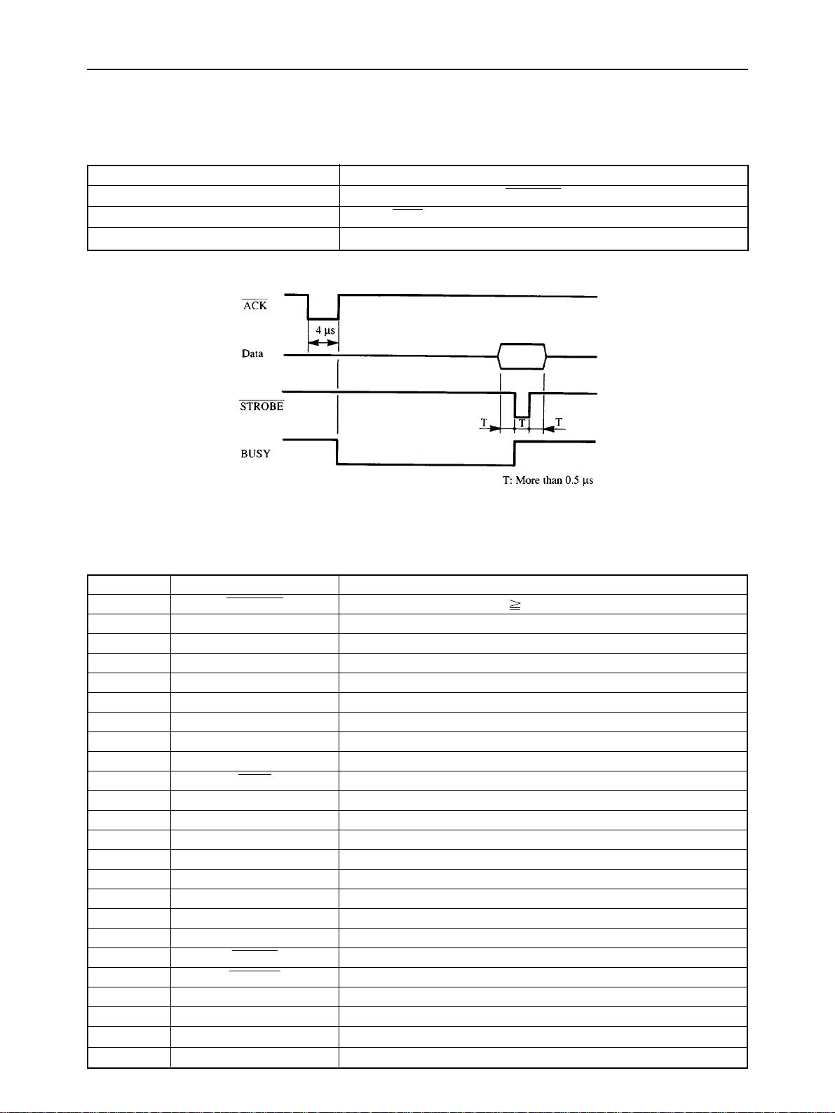
4-1. General Specifications
Item Specifications
Synchronization System Via externally supplied STROBE pulse
I/F Protocol By ACK and BUSY signals
Logic Level Compatible with TTL level
Fig. 1-5 Timing Charts of Parallel Interface
4-2. Connector Signals
Pin No Signal Name Function Description
1 STROBE Goes from high to low (for 0.5µs) when active.
2 DATA1 High when active.
3 DATA2 High when active.
4 DATA3 High when active.
5 DATA4 High when active.
6 DATA5 High when active.
7 DATA6 High when active.
8 DATA7 High when active.
9 DATA8 High when active.
10 ACK 4µs low pulse acknowledges receipt of data.
11 BUSY Low when printer ready to receive data.
12 PAPER END High when paper out.
13 SELECT High when printer is on-line.
14,15 NC Unused.
16 SIGNAL GND Signal ground.
17 CHASSIS GND Chassis ground.
18 NC Unused.
19 ~ 30 GND Twisted pair ground return.
31 RESET When this input signal is low, printer is reset.
32 ERROR Outputs low when printer cannot continue, due to an error.
33 EXT GND External ground.
34 NC Unused.
35 +5V +5V DC output from printer.
36 NC Unused.
– 8 –
Page 13

CHAPTER 2
THEORY OF OPERATION
1. Block Diagram .....................................................................................................11
2. Mechanism...........................................................................................................12
2-1. Overview................................................................................................................ 12
2-2. Ink Cartridge.......................................................................................................... 13
2-2-1. Ink Jet Mechanism ......................................................................................... 13
2-2-2. Ink Cartridge Structure .................................................................................. 13
2-2-3. Ink Jet Head Unit Structure ........................................................................... 14
2-3. Purge Unit.............................................................................................................. 17
2-3-1. Purge Unit Functions..................................................................................... 17
2-3-2. Purge Unit Structure ...................................................................................... 17
2-4. Carriage Section ................................................................................................... 19
2-4-1. Carriage Section Functions .......................................................................... 19
2-4-2. Carriage Section Structure............................................................................ 19
2-5. Paper Feed Section .............................................................................................. 22
2
2-5-1. 3-way Paper Feed Section ............................................................................. 22
2-5-2. Paper End Detection Section ........................................................................ 22
3. Logic Board .........................................................................................................24
3-1. Logic Board Functions......................................................................................... 24
3-2. Control Section Block Diagram........................................................................... 26
3-3. Control Section Components .............................................................................. 27
3-4. Power Supply Section Block Diagram................................................................ 28
3-5. Power Supply Section Components ................................................................... 29
4. Auto Sheet Feeder...............................................................................................31
4-1. Gear Train.............................................................................................................. 31
4-2. Spring Clutch ........................................................................................................ 31
Page 14

THEORY OF OPERATION
– 10 –
Page 15
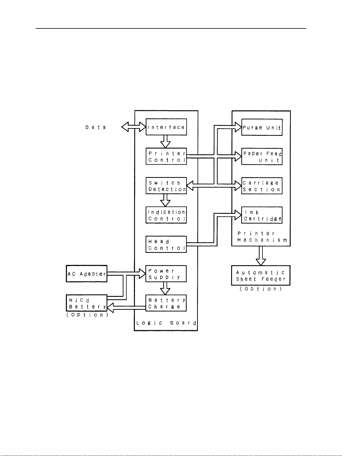
1. Block Diagram
The block diagram of this printer is shown in Figure 2-1.
THEORY OF OPERATION
Fig. 2-1 Block Diagram
– 11 –
Page 16
THEORY OF OPERATION
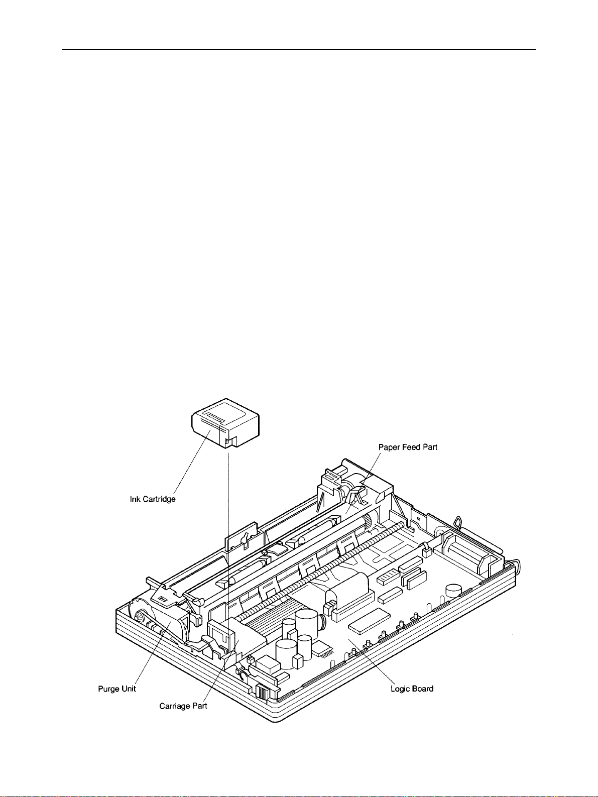
2. Mechanisms
2-1. Overview
This section explains the outline of the printer mechanism. The following sections explain each details.
a) Ink cartridge
The ink cartridge contains the 64-nozzle ink jet head with resolution of 360 DPI and ink tank.
b) Purge unit
The purge unit, drive by the carriage motor, maintains the ink jet nozzles of the ink cartridge to keep the best
printing quality.
c) Carriage part
The carriage, driven by the carriage motor, moves horizontally to the print paper with logical seeking. The carriage
motor drives either the purge unit or the carriage.
Printing signals are transmitted from the logic board to the ink cartridge on the carriage through the ribbon cable.
d) Paper feed part
The paper feed parts, driven by the paper feed motor, rotates the feed roller and moves the print paper vertically.
When the printer is placed horizontally, paper can be fed from the top of the printer. When the printer is placed
vertically, paper can be inserted from the bottom slot of the printer for flat feeding and can be fed from the optional
auto sheet feeder. Since the printer has no paper feed knob for manual feeding, paper is always fed using control
buttons.
Fig. 2-2 Internal View
– 12 –
Page 17
THEORY OF OPERATION
2-2. Ink Cartridge
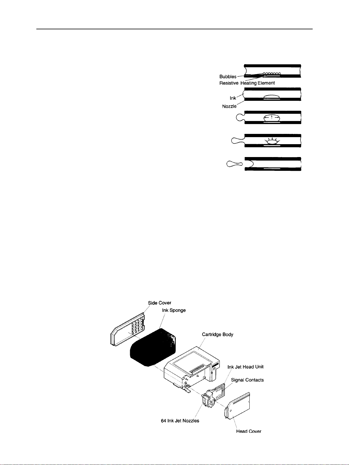
2-2-1. Ink Jet Printing Mechanism
The ink jet printing system prints characters and graphics by firing ink
drops at the paper from thin nozzles. Heating the ink in these nozzles
produces bubbles that quickly expand and eject the ink. The heat is
generated by applying electrical pulses to the heating elements built into
each nozzle. Each pulse serves a two-fold purpose.
(1) The electrical pulse first generates heat that vaporizes the ink almost
instantly.
The resulting bubble generates a pressure wave that ejects an ink drop
from the nozzle.
(2) A vacuum is then produced as the bubble contracts after the pulse
ends.
This draws fresh ink into the nozzle.
2-2-2. Ink Cartridge Structure
a) Side cover
This plastic cover has been adhered to the cartridge body to prevent leakage of ink from the ink sponge.
b) Ink sponge
The ink sponge contains about 20 grams of black ink for printing about 450 pages of regular office paper (ordinary
paper).
c) Cartridge body
The plastic cartridge body holds the ink sponge and ink jet head unit.
d) Ink jet head unit
The ink jet head unit loads ink to the 64 ink jet nozzles from the tip of the joint pipe that contacts with the ink sponge.
Printing signals are transmitted from the signal contacts.
e) Head cover
The plastic head cover protects the ink jet head unit.
Fig. 2-3 Exploded View of Ink Cartridge
– 13 –
Page 18
THEORY OF OPERATION
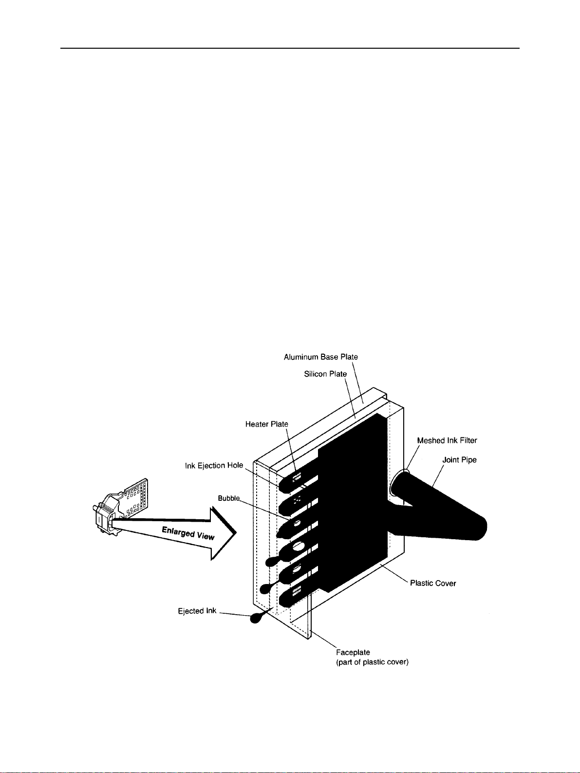
2-2-3. Ink Jet Head Unit Structure
a) Ink jet nozzles
The ink in the ink sponge pass through the meshed ink filter to remove dust, and is flowed to the ink jet nozzles
through the joint pipe. When the head drive current flows through the heater plate of a nozzle, the ink boils and
bubbles are produced, forming into one large bubble. The head drive current is cut off before a drop of ink is ejected
from the nozzle, but bubbling is grown because of the remaining heat on the heater, and the drop of ink is ejected
from the nozzle at about 12 m/s. After ejected the drop of ink, the nozzle is refilled with ink.
The ink jet head is formed on the silicon plate based on semiconductor technology.
The heater and its electrical wiring are formed on the plate.
A plastic cover with face plate and 64 nozzles is bonded to the plate.
Fig. 2-4 Ink Jet Nozzles
– 14 –
Page 19
THEORY OF OPERATION
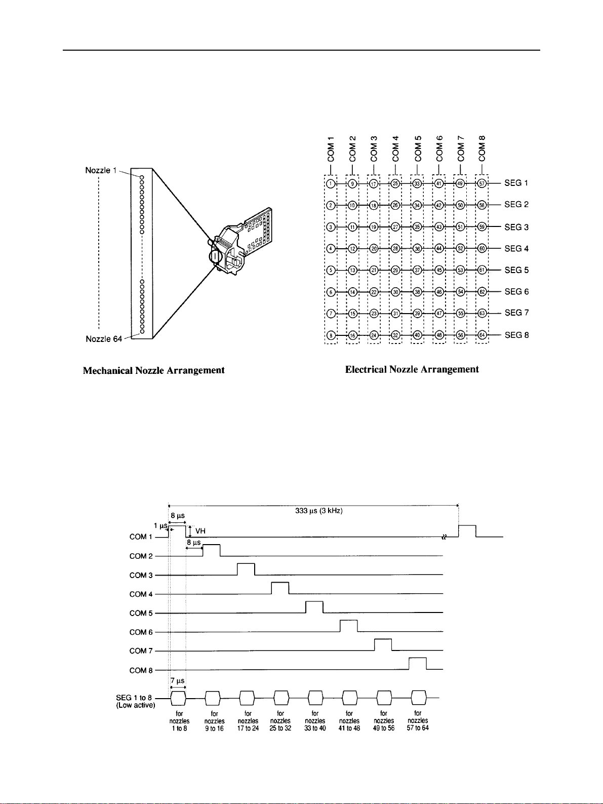
b) Nozzle arrangement
The 64 ink jet nozzles are arranged in a line at intervals of 1/360 inch. The upper 60 nozzles are used for actual
printing. The 64 heater plates are controlled by the matrix structure of the 8 COM signal circuits and 8 SEG signal
circuits.
Fig. 2-5 Nozzle Arrangement
c) Printing signals
The COM signal connects circuits COM1 to COM8 to the head drive power supply (VH) in order so that the 64
nozzles are ready to print in units of 8 nozzles.
The SEG signal connects the SEG circuit (SEG1 to SEG8) nozzles to be used for printing to the ground while the
COM signal is connected to the head drive power supply, and applies the heater voltage to the heater plate.
Fig. 2-6 Printing Signals
– 15 –
Page 20
THEORY OF OPERATION
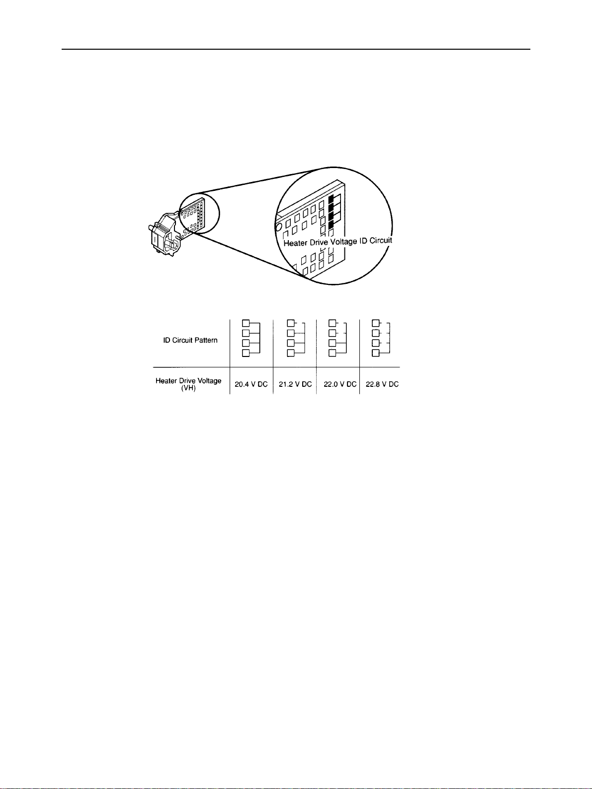
d) Heater voltage
One of four heater voltage levels that determine the ink jet speed is selected to correct any manufacturing variations
in the ink jet head units. The heater voltage ID is indicated by the PCB pattern of the contact points of the ink jet
head unit, and is used to switch the heater voltage output of the printer heater drive voltage supply circuit.
Fig. 2-7 Heater Drive Voltage ID
– 16 –
Page 21

THEORY OF OPERATION
2-3. Purge Unit
2-3-1. Purge Unit Functions
a) Capping function
When printing does not take place for more than five seconds or when the printer goes offline, the capping function
pushes the rubber cap of the purge unit against the face plate (nozzle part) of the ink cartridge to prevent the ink from
drying up or leaking.
b) Cleaning function
To maintain high quality printing with the ink cartridge, the cleaning function is performed for about 12 seconds
when the “Head cleaning buttons” are pressed until the beeper sounds at the state of the power being on or the printer
being online. For cleaning, a wiping operation takes place to wipe off paper fiber and ink remaining on the face plate
of the ink cartridge, and a pumping operation takes place to suck about 0.1cc of ink from the capped ink cartridge
and fill the nozzles with fresh ink.
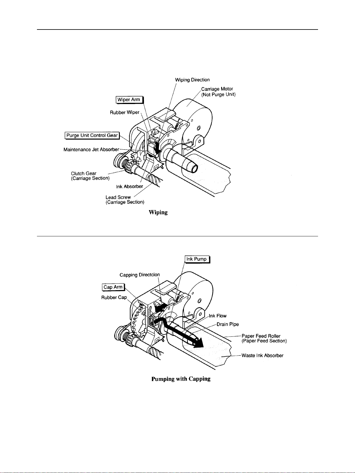
2-3-2. Purge Unit Structure
a) Purge unit control gear
The purge unit control gear is driven by the clutch gear of the lead screw, which is driven by the carriage motor.
This gear functions as a cam that drives the purge unit rubber wiper, cap, and pump, and controls the overall
movement of the purge unit operations.
b) Wiper arm unit
The wiper arm has a rubber wiper and a maintenance jet absorber. The rubber wiper wipes off the face plate of the
ink cartridge from top to bottom every 60 seconds during cleaning, before starting printing, and during printing.
The maintenance jet absorber absorbs the ejected ink from the nozzles as a test to stabilize the nozzles when the
power is switched on, before starting printing and every 12 seconds while printing. The stains on the rubber wiper
and the ink in the maintenance jet absorber are mopped up by the ink absorber when the wiper arm goes down.
c) Cap unit
The cap arm with its rubber cap advances and caps the ink cartridge when the wiper arm goes down. The rubber
cap connects to the ink pump and sucks ink from the ink cartridge during cleaning.
d) Pump unit
The pipe-shaped pump unit sucks ink through the rubber cap and runs it to the waste ink absorber in the paper feed
roller.
– 17 –
Page 22
THEORY OF OPERATION
Fig. 2-8 Purge Unit
– 18 –
Page 23

THEORY OF OPERATION
2-4. Carriage Section
2-4-1. Carriage Section Functions
a) Ink cartridge mounting function
The carriage fixes the ink cartridge mechanically and connects the electrical circuits to the logic board.
b) Carriage drive function
The carriage is moved horizontally over the print paper by the carriage motor.
c) Head gap adjustment function
The gap between the head and print paper can be adjusted with the head gap dial to suit the paper thickness.
d) Purge unit drive function
The carriage motor returns the carriage to its home position and drives the purge unit.
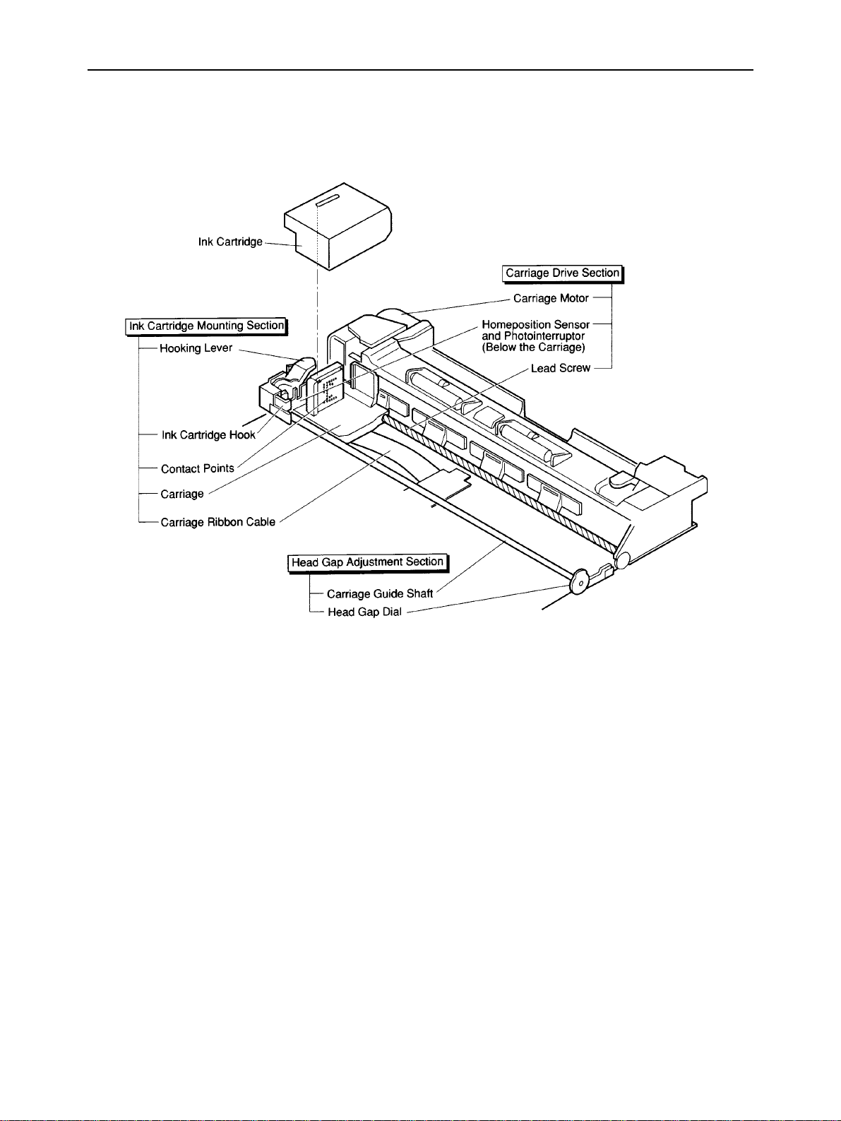
2-4-2. Carriage Section Structure
a) Ink cartridge mounting section
The hook that is moved with the hooking lever fixes the ink cartridge on the carriage. When the ink cartridge is fixed
on the carriage, the contact portion of the ribbon cable connects with the contact portion of the ink jet head unit to
transfer printing signals from the logic board.
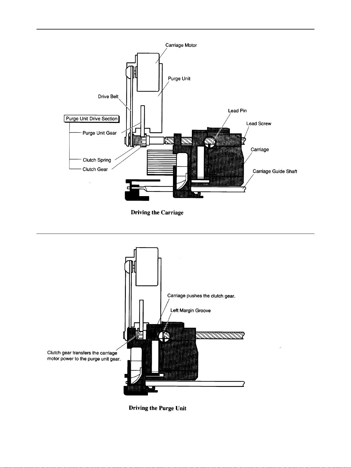
b) Carriage drive section
The DC stepping carriage motor rotates the lead screw via the drive belt. The carriage moves horizontally over the
print paper driven by lead pin, which engages in the groove of the lead screw. For the carriage position, the
photocoupler home position sensor under the carriage detects the photointerrupter (part of the guide shaft holder)
at the left of the carriage guide shaft, and logical seeking takes place using a stepping pulse transmitted to the
carriage motor.
c) Head gap adjustment function
The eccentric carriage guide shaft can be adjusted with the head gap dial on the bottom of the printer to match the
head gap to the print paper thickness. The head gap is about 0.04 inch (1 mm) when the dial is turned fully in the
direction of the cut sheet mark and about 0.075 inch (1.9 mm) when turned fully in the direction of the envelope
mark. When the optional auto sheet feeder is used, set the dial to the middle point between the cut sheet mark and
envelope mark where the dial clicks.
d) Purge unit drive section
When the lead pin enters the left margin groove, the carriage pushes the clutch gear of the lead screw to the purge
unit, and transmits the carriage motor power to the purge unit control gear.
– 19 –
Page 24
THEORY OF OPERATION
Fig. 2-9 Carriage
– 20 –
Page 25
THEORY OF OPERATION
Fig. 2-10 Purge Unit Drive Section
– 21 –
Page 26
THEORY OF OPERATION
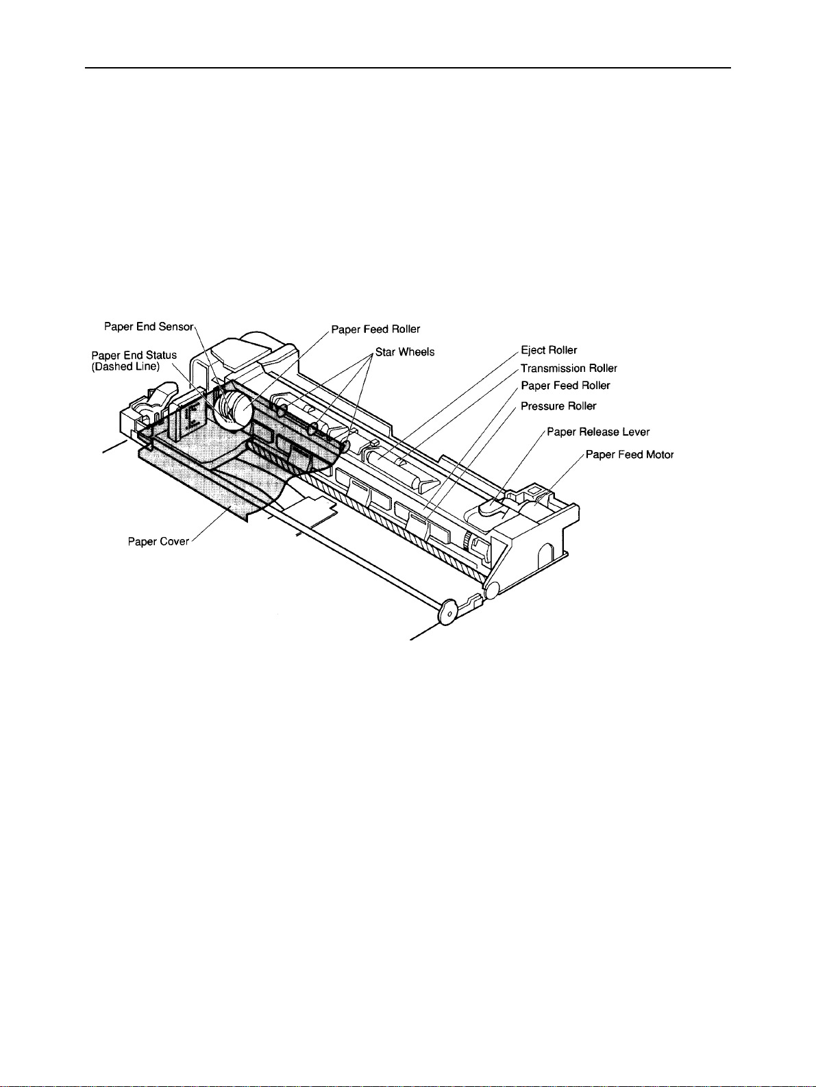
2-5. Paper Feed Section
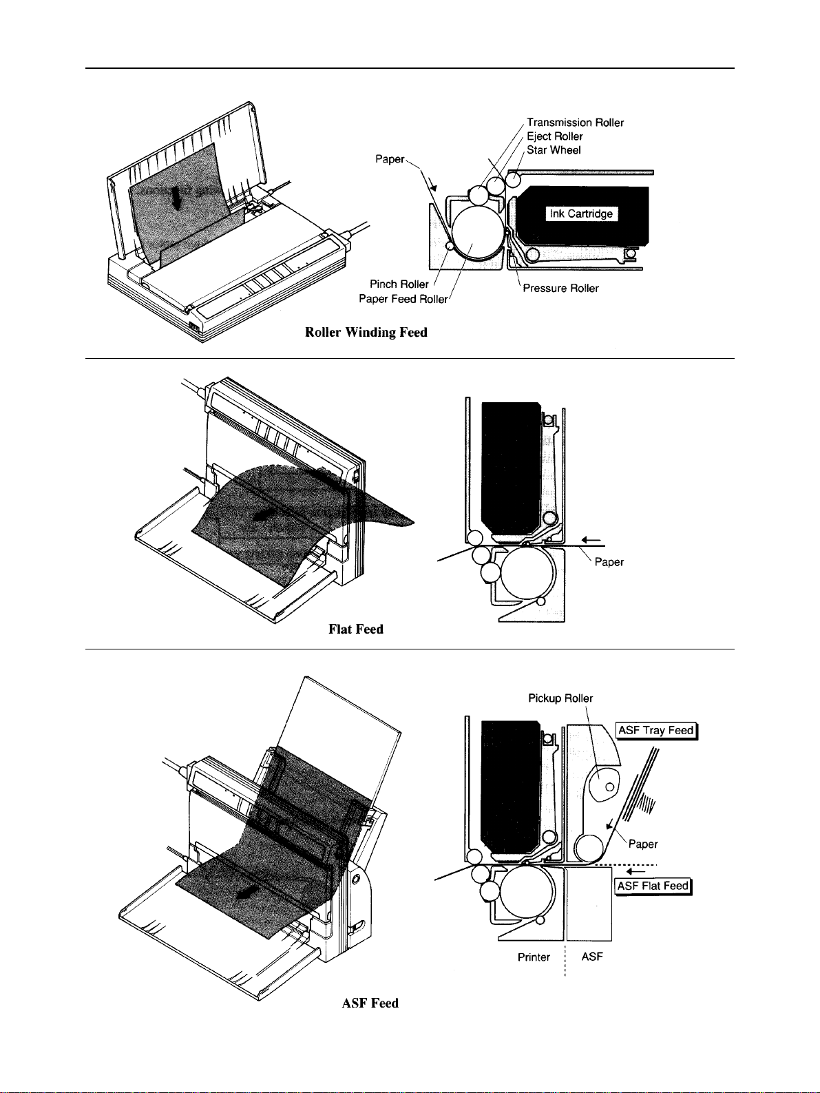
2-5-1. 3-way Paper Feed Section
The 3-way paper feed section is driven by the DC stepping paper feed motor. In roller-wind feeding, print paper is inserted
from the top rear of the printer, and fed around the paper feed roller. In flat feeding, print paper is inserted from the paper
slot in the bottom part of the printer, and fed by the paper feed roller and pressure roller. In ASF feeding, when the optional
auto sheet feeder is fitted to the printer, automatic paper feed and manual flat feed can be done.
2-5-2. Paper End Detection Section
The leaf switch paper end sensor at the lower left of the feed roller detects print paper.
Fig. 2-11 Paper Feed Section
– 22 –
Page 27
THEORY OF OPERATION
Fig. 2-12 3-way Paper Feed
– 23 –
Page 28

THEORY OF OPERATION
3. Logic Board
The logic board converts data from the interface to printing signals or printer operational signals
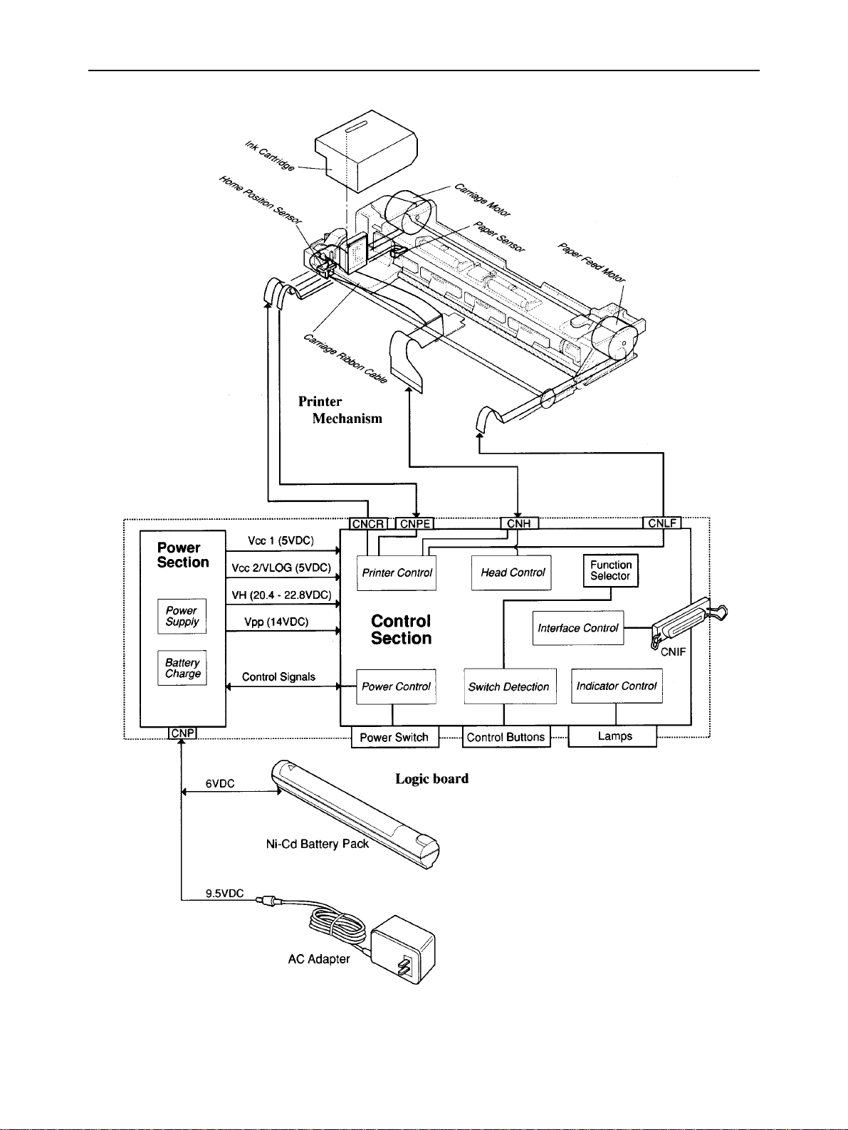
3-1. Logic Board Functions
The logic board, consisting of a control section and a power supply section, provides the following functions;
a) Printer control
The control section logically controls printer operations with the paper feed motor and carriage motor according
to the printer state monitored with a paper sensor and a home position sensor.
b) Interface control
The control section converts data from the computer via a parallel interface to print data and printer control
commands.
c) Head control
The control section converts print data to print signals for the ink cartridge and controls printing.
d) Power control
The control section controls the power supply circuit according to signals from the control buttons, power switch
and outputs from the power supply circuit.
e) Switch detection
The control section detects the states of the control buttons and function selectors.
f) Indicator control
The control section displays the printer operating states with indicator lamps.
g) Power supply
The power supply section makes various DC voltages for the printer from the Ni-Cd battery pack and AC adapter.
h) Battery charger
When the power is switched on with an AC adapter connected to the printer and the
until the beeper sounds, the Ni-Cd battery pack is charged by power supply section.
ON LINE
button is held down
– 24 –
Page 29
THEORY OF OPERATION
Fig. 2-13 Block Diagram of Logic Board
– 25 –
Page 30
THEORY OF OPERATION
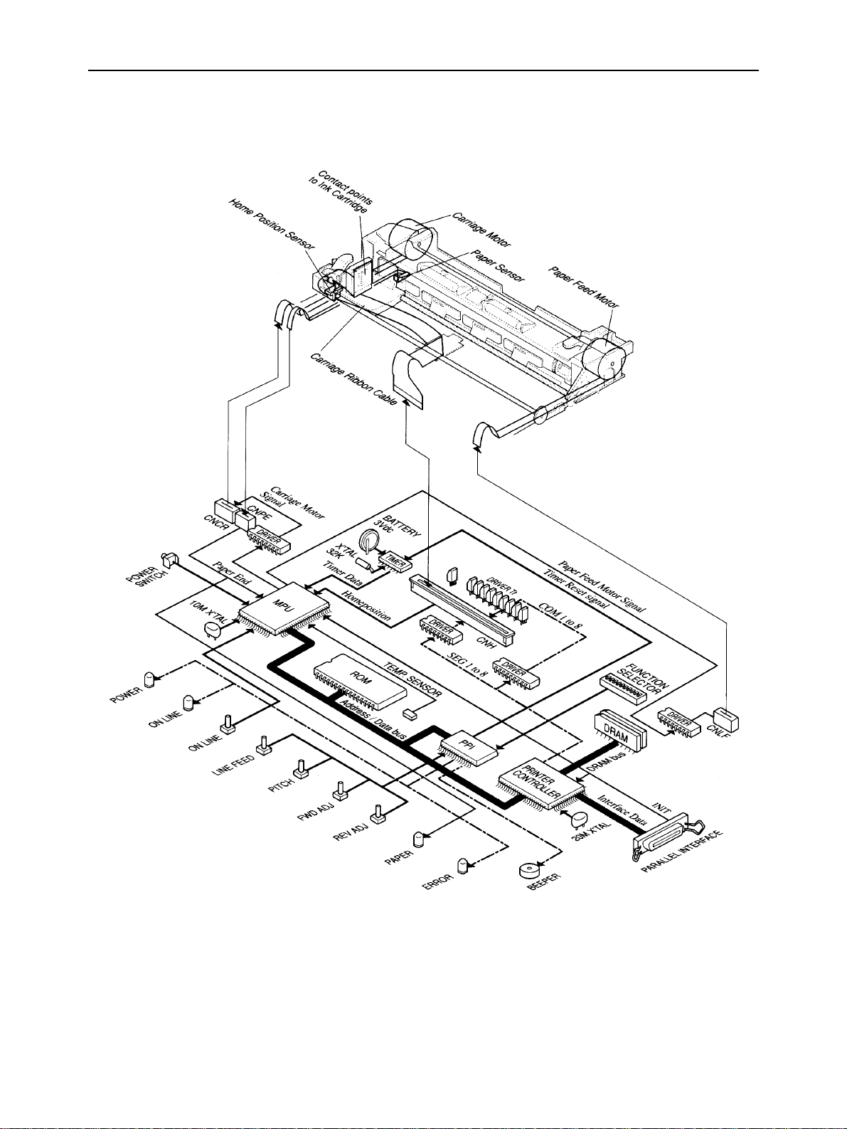
3-2. Control Section Block Diagram
Fig. 2-14 Control Section Block Diagram
– 26 –
Page 31

THEORY OF OPERATION
3-3. Control Section Components
a) MPU (Microprocessor)
The MPU (TMP90C840AF) contains an 8-bit CPU, an 8-Kbyte ROM, a 256-Kbyte RAM, a 20-bit address bus port,
an 8-bit data bus port, a 2-channel stepping motor controller, a serial interface, an interrupt controller, and input
ports.
b) Printer controller
The printer controller (TC24SC090AF) contains the interface controller, DRAM controller, print head controller,
and address decoder. The independent 20 MHz clock input to the printer controller time the interface and DRAM
bus. The bus timing with the CPU is determined by 2.5 MHz CLK0 input from the CPU.
c) PPI
The PPI (82C55AFP) is controlled by the CPU bus.
• Input port
The input port detects the input states of the
and the settings of the function selectors.
• Output port
The output port switches the POWER, ONLINE, and ERROR lamps on and off, controls the buzzer, and resets the
timer after cleaning.
LINE FEED PITCH FWD ADJ REV ADJ
, and,,
buttons
d) DRAM
The DRAM is used as a receive buffer/font download area, single-line print buffer, and work area.
– 27 –
Page 32

THEORY OF OPERATION
3-4. Power Supply Section Block Diagram
Fig. 2-15 Power Section Block Diagram
– 28 –
Page 33

THEORY OF OPERATION
3-5. Power Supply Section Components
a) Input power sources
Power is supplied to the power supply section from two input power sources: a 9.5 VDC outputs AC adapter and
a 6 VDC outputs Ni-Cd battery pack.
When the DC plug of AC adapter is inserted into the DC jack, the power supply is automatically switched from the
Ni-Cd battery to the AC adapter.
The DC input passes through a 4.0 A fuse and a noise filter, and its voltage is checked by the MPU A/D converter
to determine whether it is from the 9.5 VDC AC adapter or the 6 VDC Ni-Cd battery pack. This determination makes
the low-battery detection function and auto power-off function be enabled when the Ni-Cd battery pack is being
used. When the Ni-Cd battery pack is being charged, the determination confirms DC input supplied from the AC
adapter and makes the auto charge-off function be enabled.
b) Vcc1 output
The +5 VDC Vcc1 produced by the regulator IC is supplied for the MPU, MPU power-on reset IC, and power switch
pull-up voltage even when the power is off. This is because the power switch on/off signal must be read even while
the power is off.
c) Vcc2/VLOG output
The +5 VDC Vcc2 and VLOG produced by the zener diode via the 0.3 A fuse is supplied as a power for the logic
for other than the MPU, and the power-on reset circuit for the printer controller and PPI. When the power is switched
on, the MPU reset signal outputs Vcc2 when the printer controller is reset to activate the printer controller in a stable
condition. When the power is switched off, the MPU stops the Vcc2 output.
d) Vpp output
The +14 VDC Vpp produced by the DC/DC converter is supplied for the carriage motor driver, paper feed motor
driver, buzzer, and Vcc2 control circuit. To stabilize the output voltage, the Vpp-ref voltage produced from the Vpp
output is fed back to the DC/DC converter control IC.
e) VH output
The VH produced by the DC/DC converter is supplied for the print signal SEG driver IC, COM driver transistors,
and the ink cartridge warm-up heater driver transistor.
One of +20.4 V, +21.2 V +22.0 V, and +22.8 V is selected as the VH output voltage by feeding back the VH-ref
voltage based on the ink cartridge head rank pattern to the DC/DC converter control IC.
– 29 –
Page 34

THEORY OF OPERATION
f) Battery charge output
When the power is switched on with an AC adapter connected and the online button is held down until the beeper
sounds, the power lamp flashes and the MPU connects the Vpp output to the battery charge circuit to begin charging
the Ni-Cd battery pack.
The MPU A/D converter checks the battery voltage being charged every 2 minutes.
If it is less than 6 V, the Ni-Cd battery pack is considered overdischarge or defective and the power and error lamps
flash alternately.
When about 10 hours elapse after charging begins, the auto charge-off function automatically stops the charging
and switches the printer off.
– 30 –
Page 35

THEORY OF OPERATION
4. Auto Sheet Feeder
This section explains the outline of the internal components of the auto sheet feeder.
4-1. Gear Train
The gear train, driven by the printer feed roller, rotates the pickup roller and feed roller.
4-2. Spring Clutch
The spring clutch controls the power from the gear train to the pickup roller by rotating the printer feed roller forward or
backward. The position of this clutch is initialized when the printer power is switched on.
When paper is loaded to the printer, the feed roller rotates slightly backward to engage the clutch, then the pickup roller
feeds the topmost sheet of paper in the paper bin into the printer. When the paper end sensor detects paper loading, the
printer stops the paper to the print starting position on the first line with a top margin of about 0.12 inch (3 mm). When
the pickup roller is completely detached from the sheet, the clutch is disengaged and the pickup roller stops.
Fig. 2-16 ASF Internal View
– 31 –
Page 36

THEORY OF OPERATION
– 32 –
Page 37

CHAPTER 3
ADJUSTMENTS
This section describes the head gap adjustment required for reassembling.
Please check this explanation when making maintenance inspections or when replacing parts to correct
malfunctions.
1. Adjustment Point.................................................................................................35
2. When Adjustment is Necessary.........................................................................35
2-1. When Adjustment is Absolutely Necessary....................................................... 35
2-2. When Adjustment may be Necessary................................................................. 35
2-3. Tools Required for Adjustment ........................................................................... 36
3. Adjustment Method.............................................................................................36
3-1. Preparations for Adjustment ............................................................................... 36
3
3-2. Adjustment ............................................................................................................ 37
Page 38

ADJUSTMENTS
– 34 –
Page 39

ADJUSTMENTS
1. Adjustment Point
The only printer adjustment is that of the head gap to keep the distance between the ink cartridge and printing paper
constant.
Adjust the head gap so that the distance between the ink cartridge nozzle and printing paper is about 0.04 inch (1 mm)
by rotating the adjustment dials (white) on the right and left sides of the printer mechanism.
The left adjustment dials is under the purge unit and part of it. The right adjustment dial is fitted into the paper feed base.
The head gap adjustment dials can be turned when the printer mechanism is removed from the lower case.
Fig. 3-1 Adjustment Dials
2. When Adjustment is Necessary
The head gap must be adjusted when the default adjustment dial position is changed.
2-1. When Adjustment is Absolutely Necessary
• When the purge unit is replaced.
2-2. When Adjustment may be Necessary
• When the adjustment dial position is changed when the carriage is removed.
• When the lead screw is removed and the adjustment dial position is changed.
If it is unnecessary to change the adjustment dials in servicing: mark the original positions of the dials on the chassis with
a felt-tipped pen. (Refer to item 5 of chapter 4 for the marking method.)
– 35 –
Page 40

ADJUSTMENTS
2-3. Tools Required for Adjustment
UseTool
Phillips screwdriver For the purge unit fastening screws
Gap gauges (0.5 mm) For head gap measurements (Three gauges are necessary.)
Ink cartridge Same as normal ink cartridge (Do not use user’s ink cartridge since the gauge may
strike against its nozzle.)
3. Adjustment Method
3-1. Preparation for Adjustment
1) Remove the printer mechanism from the lower case. (Refer to item 5 of chapter 4 for the disassembly procedure.)
2) Place and lock the ink cartridge on the carriage and turn the black head gap dial on the right side of the carriage guide
shaft clockwise until it stops.
3) Turn the white adjustment dial (R) on the right side of the lead screw counterclockwise until it stops.
4) Loosen the purge unit fastening screw, then turn the white adjustment dial (L) under the purge unit so that the mark
faces the carriage motor side.
Fig. 3-2 Preparations for Adjustment
– 36 –
Page 41

ADJUSTMENTS
3-2. Adjustment
1) Set the release lever upright, insert two gap gauges into the places shown in the following figure from under the
printer mechanism, then push the release lever back to its original position.
Caution: Take care not damage the paper feed roller when inserting the gauges.
2) Turn the carriage drive belt counterclockwise and move the carriage so that the ink cartridge nozzles are facing the
gap gauges placed on the left side.
Fig. 3-3 Head Gap Adjustment (1)
– 37 –
Page 42

ADJUSTMENTS
3) Insert the third gap gauge between the set gap gauge and nozzle.
4) Turn the white adjustment dial (L) under the purge unit until there is no clearance between the two gauges and the
ink carriage nozzle.
5) Push the ink cartridge to the right and move it so that if faces the gap gauges on the right side.
6) Turn the white adjustment dial (R) on the right side of the lead screw until there is no clearance between the two
gauges and the ink carriage nozzle.
7) When the head gap is adjusted at one place, the adjusted head gap at the other place changes. Therefore, adjust the
right and left head gaps several times.
8) When the adjustment is complete, remove the gap gauges, then retighten the purge unit fastening screw.
Fig. 3-4 Head Gap Adjustment (2)
– 38 –
Page 43

CHAPTER 4
PARTS REPLACEMENT
This chapter explains disassembly and reassembly of the printer. Note the following precautions during
disassembly and reassembly.
1. Disconnect the printer from the wall outlet before servicing it.
2. Assembly is the reverse of disassembly unless otherwise specified.
3. Lubrication information is not provided in this chapter. Refer to item 3 in Chapter 5.
1. Battery Cover.......................................................................................................41
2. Paper Cover .........................................................................................................41
3. Upper Cover.........................................................................................................42
4. Logic Board .........................................................................................................42
5. Printer Mechanism ..............................................................................................43
6. Power Switch ...................................................................................................... 43
7. Purge Unit ............................................................................................................44
8. Carriage Ribbon Cable Holder ...........................................................................44
9. Lead Pin Holder ...................................................................................................45
10. Lead Screw ..........................................................................................................45
11. Carriage Ribbon Cable........................................................................................46
12. Carriage Guide Shaft...........................................................................................46
13. Transmission Roller............................................................................................47
14. Paper Feed Roller................................................................................................47
15. Paper Feed Motor................................................................................................48
4
16. Pinch Roller .........................................................................................................48
17. Pressure Plate Holder .........................................................................................49
18. ASF Instruction Panel .........................................................................................49
19. ASF Covers..........................................................................................................50
20. ASF Locking Levers............................................................................................50
21. ASF Paper Guide Table.......................................................................................51
22. ASF Paper Lifting Plate.......................................................................................51
23. ASF Guide Plates ................................................................................................52
24. ASF Paper Guides ...............................................................................................52
25. ASF Feed Roller...................................................................................................53
26. ASF Pick-up Roller Shaft ....................................................................................53
Page 44

PARTS REPLACEMENT
– 40 –
Page 45

PARTS REPLACEMENT
1. Battery Cover
(1) Remove
• Printer stand [1]
Rotate the printer stand [1]135 degrees and pull it.
• Battery cover [2]
2. Paper Cover
(1) Remove
• Top cover [1]
• Paper cover [2]
– 41 –
Page 46

PARTS REPLACEMENT
3. Upper Cover
(1) Remove
• Battery cover according to the procedure de-
scribed in item 1.
• Paper cover according to the procedure
described in item 2.
• Screw [1]
• Upper cover [2]
Press a minus driver into joints [3] of upper
cover [2] and lower cover [4] for separation.
4. Logic Board
(1) Remove
• Upper cover according to the procedure
described in item 3.
• Two screws [1]
• Screw [2]
• Five connectors [3]
• Logic board [4]
– 42 –
Page 47

PARTS REPLACEMENT
5. Printer Mechanism
(1) Remove
• Logic board according to the procedure
described in item 4.
• Two screws [1]
• Printer mechanism [2]
Mark the dial positions [3] for the head gap
adjustment.
• Paper end sensor [4]
6. Power Switch
(1) Remove
• Logic board according to the procedure
described in item 4.
• Power switch unit [1].
Press a minus driver into joints [2] of power
switch unit and lower cover for separation.
• Power switch [3]
• Switch holder [4]
– 43 –
Page 48

PARTS REPLACEMENT
7. Purge Unit
(1) Remove the printer mechanism according to the
procedure described in item 5.
(2) Move the carriage unit [1]
(3) Remove
• Carriage drive belt [2]
Press the carriage motor in the direction of the
arrow for separation.
• Screw [3]
• Carriage shaft stopper [4]
• Purge unit [5]
Release the three joints [6] for separation
• Carriage motor [7]
• Belt tension spring [8]
(4) Adjust
• Head gap
Refer to Chapter 3.
8. Carriage Ribbon Cable Holder
(1) Remove
• Printer mechanism according to the procedure
described in item 5.
• Carriage ribbon cable holder [1]
– 44 –
Page 49

PARTS REPLACEMENT
9. Lead Pin Holder
(1) Remove
• Purge unit according to the procedure described
in item 7.
• Lead screw [1] from the printer mechanism.
• Lock cover [2]
Release the hook [3] for separation
• Locking lever [4]
• Ink cartridge lock [5]
• Spring [6]
• Carriage cover [7]
Release the two hooks [8] for separation
• Lead pin holder [9]
Caution in assembly:
Use new Lock cover [2], if this parts is removed.
10. Lead Screw
(1) Remove
• Lead pin holder according to the procedure described in item 9.
• Lead pin [1]
• Lead screw [2]
Caution in assembly:
Insert the lead pin [1] in the groove [3].
– 45 –
Page 50

PARTS REPLACEMENT
11. Carriage Ribbon Cable
(1) Remove
• Lock cover and carriage cover according to the
procedure described in item 9.
• Ribbon Cable lower holder [1]
• Ribbon Cable upper holder [2]
• Contact pad [3]
• Carriage ribbon cable [4]
Release the hook [5] for separation
Caution in assembly:
Bend the ribbon at the four marks [6]
12. Carriage Guide Shaft
(1) Remove
• Lead screw from the printer mechanism accord-
ing to the procedure described in item 9.
• Carriage guide shaft [1]
• Guide shaft holder [2]
(2) Adjust
• Head gap
Refer to Chapter 3.
– 46 –
Page 51

PARTS REPLACEMENT
13. Transmission Roller
(1) Remove
• Carriage guide shaft according to the procedure
described in item 12.
• Four pressure plates [1]
• Four pressure rollers [2]
• Platen plate [3]
Caution: The hook [4] of the platen plate [3] is
very weak.
• Paper separator [5]
• Two ejectrollers [6]
• Two roller shafts [7]
• Two transmission rollers [8]
14. Paper Feed Roller
(1) Remove
• Platen plate according to the procedure described
in item 13.
• Feed roller stabilizer [1]
Press a minus driver into joints of feed roller
stabilizer [1] and base for separation.
• Lead screw holder [2]
• Adjust dial [3]
• Release rod [4]
• Paper feed roller [5]
• Release crank [6]
• Feed roller holder [7]
– 47 –
Page 52

PARTS REPLACEMENT
15. Paper Feed Motor
(1) Remove
• Paper feed roller according to the procedure de-
scribed in item 14.
• Paper feed motor [1]
Press a minus driver into joints of paper feed
motor [1] and paper feed base [2] for separation
• Slowdown gear [3]
• Release lever [4]
Caution in assembly:
Align these gears [5] when reassembling.
16. Pinch Roller
(1) Remove
• Paper feed motor according to the procedure
described in item 15.
• Two pinch roller leaf springs [1]
• Pinch roller release shaft [2]
• Two pinch roller holders [3]
• Two pinch rollers [4]
– 48 –
Page 53

PARTS REPLACEMENT
17. Pressure Plate Holder
(1) Remove
• Pinch roller according to the procedure described
in item 16.
• Paper feed base [1]
• Ink absorber A [2]
• Ink absorber B [3]
• Pressure plate release shaft [4]
• Two pressure plate left springs [5]
• Four pressure plate holders [6]
• Chassis [7]
Caution in assembly:
Use new one, if the paper feed base [1] is removed.
18. ASF Instruction Panel
(1) Remove the ASF assembly from the printer.
(2) Remove
• Paper support [1]
• Instruction panel [2]
– 49 –
Page 54

PARTS REPLACEMENT
19. ASF Covers
(1) Remove
• Instruction panel according to the procedure de-
scribed in item 18.
• Right cover [1]
Press a minus driver into three joints [2] for
separation.
• Release button [3]
• Left cover [4]
Press a minus driver into three joints [5] for
separation.
• Transfer gear [6]
20. ASF Locking Levers
(1) Remove
• Covers according to the procedure described in
item 19.
• Two springs [1]
• Right locking lever [2]
• Left locking lever [3]
– 50 –
Page 55

PARTS REPLACEMENT
21. ASF Paper Guide Table
(1) Remove
• Covers according to the procedure described in
item 19.
• Two shaft pins [1]
• Paper guide table [2]
• Paper tray unit [3]
• Sheet feeder base unit [4]
22. ASF Paper Lifting Plate
(1) Remove
• Paper tray unit [1] according to the procedure
described in item 21.
• Wedge pin [2]
• Paper lifting plate [3]
• Spring [4]
– 51 –
Page 56

PARTS REPLACEMENT
23. ASF Guide Plates
(1) Remove
• Paper lifting plate according to the procedure
described in item 22.
• Left guide looking lever [1]
• Right guide looking lever [2]
• Two guide locking shafts [3]
• Two rubber rings [4]
• Two washers [5]
• Left guide plate [6]
• Right guide plate [7]
24. ASF Paper Guides
(1) Remove
• Guide plates according to the procedure
described in item 23.
• Two paper stoppers [1]
• Four slide guides [2]
• Right paper guide [3]
• Left paper guide [4]
• Paper tray [5]
– 52 –
Page 57

PARTS REPLACEMENT
25. ASF Feed Roller
(1) Remove
• Sheet feeder base unit according to the procedure
described in item 21.
• Gear holder [1]
Release the three joints [2] of gear holder [1] and
sheet feeder base unit for separation.
• Idol gear [3]
• Slowdown gear [4]
• Feed roller [5]
• Two rubber rings [6]
26. ASF Pick-up Roller Shaft
(1) Remove
• Feed roller according to the procedure described
in item 25.
• Arm pressure spring [1]
• Positioning arm [2]
• Pick-up roller shaft [3]
• Two pick-up rubbers [4]
• Control cam [5]
• Clutch spring [6]
• Pick-up gear [7]
– 53 –
Page 58

GENERAL SPECIFICATIONS
– 2 –
Page 59

CHAPTER 5
PRECAUTIONS AND MAINTENANCE
1. Precautions..........................................................................................................57
1-1. High-Temperature Components.......................................................................... 57
1-2. Disposing of Ni-Cd Battery .................................................................................. 57
1-3 Handling the power Supply ................................................................................. 57
1-4 Damage by Electrostatic discharge .................................................................... 58
1-5 Nozzle Protection.................................................................................................. 58
2. Maintenance.........................................................................................................59
2-1. Cleaning................................................................................................................. 59
2-2. Checks................................................................................................................... 59
3. Lubrication...........................................................................................................60
3-1. Lubricant ............................................................................................................... 60
3-2. Lubricating Method .............................................................................................. 60
3-3. Lubricated Area .................................................................................................... 60
4. List of Tools .........................................................................................................60
4-1. General Tool.......................................................................................................... 60
4-2. Special Tool........................................................................................................... 60
5
Page 60

– 56 –
Page 61

PRECAUTIONS AND MAINTENANCE
1. Precautions
1-1. High-Temperature Components
The printer logic board contains components that get hot when the Ni-Cd battery pack is being charged.
DANGER: The temperature of the resistor (R9) rises to about 212°F (100°C) during charging of the Ni-Cd battery pack.
The temperature of the regulator IC (Q14) and transistor (Q13) that produce the logic circuit Vcc rises to
about 140°F (60°C) when the printer is on.
Fig. 5-1 High Temperature Components
1-2. Disposing of Ni-Cd Battery
When you dispose of the optional Ni-Cd battery pack, follow local laws and regulations.
DANGER: To prevent explosion, do not throw the Ni-Cd battery in a fire or even near one.
1-3. Handling the power Supply
a) AC adapter
Do not use any AC adapter except the one supplied with the printer. Do not use the printer AC adapter for any other
equipment.
b) Ni-Cd battery pack
The optional Ni-Cd battery pack for portable power supply has a built-in temperature-sensitive circuit breaker that
cuts the battery circuit internally, when the battery temperature rises over 158°F (70°C) because the terminals have
been shorted together. However, to avoid damaging the battery by sudden discharge, do not short its terminals
together.
Caution : Do not disassemble the Ni-Cd battery.
– 57 –
Page 62

PRECAUTIONS AND MAINTENANCE
1-4. Damage by Electrostatic discharge
The electrostatic charge on your body, produced by the rubbing of your clothes, can damage electronic components
or change their electrical characteristics. To prevent such damage, do not touch the carriage contact between the
ink cartridge and the logic board.
Fig. 5-2 Contact Points
1-5. Nozzle Protection
To prevent the nozzles clogging, do not touch the nozzles or wipe them with tissue paper, etc. Do not leave the
cartridge outside the printer without the head cover and sealing tape.
The ink cartridge cannot be disassembled or washed.
Fig. 5-3 Ink Cartridge
– 58 –
Page 63

PRECAUTIONS AND MAINTENANCE
2. Maintenance
In order to maintain the optimum performance of this printer and to prevent troubles, maintenance must be carried out
according to the following items.
2-1. Cleaning
(1) Removal of dirt
Clean the printer regularly to avoid print problems. If the printer cover becomes dirty with ink mist or paper debris,
wipe it away with a soft, wet cloth.
Caution:1. Turn the printer off when cleaning it.
2. Cleaning the printer body with volatile liquids like thinner or benzine will damage the surface of the body.
3. Never wipe the head of the ink cartridge with a cloth.
4. The ink is not harmful for human body, but contains isopropyl alcohol 67-63-0.
Do not swallow it or splash into your eyes. The ink characteristics is water soluble, but contains dye. Ink
cannot be removed if it gets on your clothes.
5. During cleaning, be careful not to moisten or damage electronic parts, wiring, or mechanical parts.
(2) Removal of dust, pile, etc.
Vacuum cleaning (with an electric cleaner) is preferred. Remove all dust, etc., inside the printer.
2-2. Checks
Checks must be carried out at two levels: “Daily check” which the operator can easily carry out during operation, and
“Periodic check” which an expert should carry out.
(1) Daily check
When the printer is used on a daily basis, check to be sure that the printer is being used properly. Make sure that
the printer is operating under the best conditions.
• Is there any foreign matter inside the printer?
(2) Periodic check
None
– 59 –
Page 64

PRECAUTIONS AND MAINTENANCE
3. Lubrication
3-1. Lubricant
For this printer, FLOIL G-311S (made by Kanto Chemicals Co.,Ltd.) are recommended.
3-2. Lubricating Method
When lubrication is carried out in assembly and disassembly, wash parts well to remove dust and dirt before lubrication.
3-3. Lubricated Area
The only lubricated area is lead screw part.
Fig. 5-4 Lubricated Area
4. List of Tools
4-1. General Tool
Tool Use
Phillips screwdriver For removing screws
Precision standard screwdriver For removing plastic parts
Tweezers For removing Ni-Cd battery terminals
Soldering iron (30 W or less) For replacing electronic components
Double-sided adhesive tape For fastening the flexible motor cable
Felt-tipped pen For marking the head gap dial positions
4-2. Special Tool
Tool Use
Gap gauges (0.5 mm) For head gap adjustments (Three gauges are necessary.)
Grease (FLOIL G-311S) Apply 0.1 to 0.2g of grease to the lead screws
Note:Refer to the Chapter 7 Parts List for the tool numbers of the special tools.
– 60 –
Page 65

CHAPTER 6
TROUBLESHOOTING
TROUBLESHOOTING
1. Errors Displayed By Indicator Lamps ...............................................................63
1-1. Error Display ......................................................................................................... 63
1-2. Error Recovery...................................................................................................... 63
2. Errors Not Displayed By Indicator Lamps ........................................................65
2-1. Error Conditions ................................................................................................... 65
2-2. Error Recovery...................................................................................................... 65
3. Auto Sheet Feeder...............................................................................................67
3-1. Error Recovery...................................................................................................... 67
6
– 61 –
Page 66

TROUBLESHOOTING
– 62 –
Page 67

TROUBLESHOOTING
1. Errors Displayed By Indicator Lamps
1-1. Error Display
The printer has a service function that displays printer errors with four indicator lamps.
Error state POWER ON LINE PAPER ERROR
RAM error Off On * On
Home position error On Off * On
Carriage control error On On * On
Paper out On Off On Flashing
Paper jam On Off Off Flashing
Low battery Flashing Off * On
Ni-Cd battery error Flashing Off * Flashing
* On when paper is empty, off when paper is set.
Note:The Ni-Cd battery error occurs when the battery is being charged. If the Ni-Cd battery pack is overdischarged, a
battery error may occur even with a normal battery. If the Ni-Cd battery pack is charged again but still produces
the error, it is defective.
1-2. Error Recovery
The errors indicated by the indicator lamps are recovered as follows:
Error
RAM error
Home position error
Note:When the logic board and the printer mechanism are repaired, replace the parts in the “Parts replacement” column.
Check/Action
1. Replace the logic board.
1. Remove any foreign objects that obstruct error the
carriage movement.
2. Check that the home position sensor is correctly installed.
3. Check the carriage ribbon cable connection.
4. Check the home position sensor:
MPU port 51 (pin #62) is high when the carriage is in the
home position.
5. Check the carriage motor: about 45 ohms per phase.
6. Replace the logic board.
When the logic board is repaired: check the carriage
motor drive pulse of IC 15. See figure 6-1.
Parts replacement
a. DRAMs (IC8,9)
b. Printer controller
(IC 3)
a. Carriage motor
b. Carriage motor
driver (IC 15)
– 63 –
Page 68

TROUBLESHOOTING
Fig. 6-1 Carriage Motor Drive Pulse (During Printing)
Error
Carriage control error
Paper out error
Paper jam error
Low battery error
Ni-Cd battery error
Check/Action
1. Apply 0.1 to 0.2 g of the grease (FLOIL G-311S) to the
lead screws.
2. Replace the printer mechanism.
1. load the paper.
2. Check the paper end sensor:
MPU port 52 (pin #63) is low while paper is present.
3. Replace the logic board.
1. Remove the jammed paper.
2. Check the paper end sensor:
MPU port 52 (pin #63) is high while paper is not present.
3. Replace the logic board.
1. Charge the Ni-Cd battery pack.
2. Replace the Ni-Cd battery pack.
1. Recharge the Ni-Cd battery pack.
2. Replace the Ni-Cd battery pack.
3. Replace the logic board.
When the logic board is repaired:
a. Check the charging signal:
PPI port PA6 (PIN #38) is high while charging.
b. Check the charging circuit:
The Q21 collector output is about 11.3 VDC (under
no load) while charging.
c. Check the charging circuit:
Check the thermal fuse in R9.
Parts replacement
a. Carriage and lead
screws
b. purge unit
a. Paper end sensor
b. MPU (IC11)
a. Paper end sensor
b. MPU (IC11)
a. IC10
b. Q21
c. R9
– 64 –
Page 69

TROUBLESHOOTING
2. Errors Not Displayed By Indicator Lamps
2-1. Error Conditions
The errors not indicated by indicator lamps include no power, printing errors, and paper feed errors.
2-2. Error Recovery
Error
No power
Check/Action
1. Set the battery switch to on.
2. Check the AC adapter output.
(9.5 VDC or higher)
3. Replace the Ni-Cd battery pack.
4. Replace the logic board.
When the logic board is repaired, Check the power
supply circuit output (Vcc1,Vcc2 and VLOG:5 VDC;
VH:24 VDC; Vpp:14VDC)
a. When all outputs are not present:
1. Check fuse F1
b. If Vcc2 is not output:
1. Check fuse F2
c. If VH is not output:
1. Check that 1.28V is fed back from VH-ref.
2. Check that the Q11 base outputs 10 µs pulses.
3. Check that the IC14 OUT1 outputs 10 µs pulses.
See figure 6-2.
d. If Vpp is not output:
1. Check that 1.28V is fed back from Vpp-ref.
2. Check that the Q12 base outputs 10 µs pulses.
3. Check that the IC14 OUT2 outputs 10 µs pulses.
See figure 6-2.
Parts replacement
a. F1
b. F2
c. R3-7
d. Q11
e. IC14
f. R97,98
g. Q12
h. IC14
Fig. 6-2 DC/DC Converter Timing (Idle State)
– 65 –
Page 70

TROUBLESHOOTING
Error
Printing errors
No paper feed
Check/Action
1. Clean the ink cartridge at least five times.
2. If dots are missing at random,printing is unstable,or
splash occurs after cleaning.
See figure 6-3.
a. Replace the ink cartridge.
b. Clean the ink cartridge at least five times.
If the printing error is not corrected, replace the purge
unit
3. If one of every eight dots is missing after cleaning.
a. Replace the ink cartridge.
b. Clean the ink cartridge at least five times.
If the printing error is not corrected, replace the logic
board.
1. Check the paper feed motor:
about 45 ohms per phase
2. Replace the logic board.
When the logic board is repaired:
a. Check the paper feed motor drive pulse of IC 2. See
figure 6-4.
b. Replace the MPU.
Parts replacement
a. Purge unit
b. IC5,6
c. Q1 to Q8
(See figure 2-5 and
2-6.)
a. Paper feed motor
b. Paper feed motor
driver (IC 2)
c. MPU
Fig. 6-3 Nozzle Test Print Pattern
Fig. 6-4 Paper Feed Pulse (During line feeding by Line Feed Switch)
– 66 –
Page 71

3. Auto Sheet Feeder
3-1. Error Recovery
TROUBLESHOOTING
Error
Feeder does not operate
No paper feed
Several sheets are fed together
Paper fed askew
Check/Action
1. Set the printer in the ASF mode by DIP switch 4.
2. Check that the ASF is correctly fitted to the printer.
3. Disassemble the ASF and check that the clutch spring,
control cam, and positioning arm are correctly operated.
4. Check that the printer functions properly.
1. Set the paper release lever to the friction feed position
(push down).
2. Press the paper bin release button.
3. Check for paper jam.
4. Clean the pick-up roller with alcohol.
1. Arrange the sheets of paper conforming to the ASF
specifications in order; and place them in the paper bin,
taking care not to deform them.
2. Set the paper guide position to fit the paper width.
1. Arrange the sheets of paper conforming to the ASF
specifications in order; and place them in the paper bin,
taking care not to deform them.
2. Set the paper guide position to fit the paper width.
3. Clean the pick-up roller with alcohol.
Parts replacement
a. Clutch spring
b. Control cam
c. Positioning arm
a. Pick-up rubber
ring
a. Pick-up rubber ring
– 67 –
Page 72

GENERAL SPECIFICATIONS
– 2 –
Page 73

CHAPTER 7 PARTS LIST
HOW TO USE PARTS LIST
(1) DRWG. NO.
This column shows the drawing number of the illustration.
(2) REVISED EDITION MARK
This column shows a revision number.
Part that have been added in the revised edition are indicated with “#”.
Part that have been abolished in the revised edition are indicated with “*”.
#1 : First edition → Second edition *1 : First edition → Second edition
(3) PARTS NO.
Parts numbers must be notified when ordering replacement parts.
(4) PARTS NAME
Parts names must be notified when ordering replacement parts.
(5) Q’TY
This column shows the number of the part used as indicated in the figure.
(6) REMARKS
When there are differences in the specifications of the fuse, destination, etc., the differences are described in
words or indicated by two letters.
US ..........U.S.A. EC ..........EC UK ..........United Kingdom
AS ..........Australia HK ..........Hong Kong
The seal number of ROM is described in this column. The “*” mark of seal number is a variable representing
on the software version.
(7) RANK
Parts marked “S” are service parts. Service parts are recommended to be in stock for maintenance.
Parts marked “N” are not stock items. They are produced on a special-order basis.
(8) REFERENCE NO.
This column shows the reference number.
7
1. Printer Assembly................................................................................................................70
1-1. Disassembly Drawing..............................................................................................................70
1-2. Parts List...................................................................................................................................71
2. Printer Mechanism .............................................................................................................72
2-1. Disassembly Drawing..............................................................................................................72
2-2. Parts List...................................................................................................................................73
3. Carriage Unit...................................................................................................................... 74
4. Special Tools ..................................................................................................................... 75
5. Wiring Scheme of Printer ................................................................................................. 76
6. Logic Board ........................................................................................................................77
6-1. Circuit Diagram ........................................................................................................................77
6-2. Component Layout ..................................................................................................................83
6-3. Parts List...................................................................................................................................85
7. Automatic Sheet Feeder ....................................................................................................89
7-1. Disassembly Drawing..............................................................................................................89
7-2. Parts List...................................................................................................................................92
8. Numerical Index .................................................................................................................93
8-1. Parts Number Index.................................................................................................................93
8-2. Reference Number Index.........................................................................................................95
Page 74

1. Printer Assembly
1-1. Disassembly Drawing
– 70 –
Page 75

1-2. Parts List
Printer Assembly
DRWG.NO. REV. PARTS NO. PARTS NAME Q'TY REMARKS RANK REF. NO.
1- 1 QG1-5272-000 PRINTER MECHANISM 1 S 80985203
2 QA2-0968-000 COVER,LOWER 1 80985177
3 *1 QG2-2396-000 BOARD,LOGIC 1 S 80985206
#1 QG2-2396-030 BOARD,LOGIC 1 S 80985206
4 F45-0132-400 INK CARTRIDGE UPC SC-10 1 FOR US S 89599030
F45-0131-500 INK CARTRIDGE JAN SC-10 1 EXCEPT US S 89599040
5 Q70-1592-410 AC ADAPTER: 120V MODEL 1 FOR US 80985030
Q70-1598-410 AC ADAPTER: 220V MODEL 1 FOR EC,HK 80985040
Q70-1591-410 AC ADAPTER: 240V(UK) MODEL 1 FOR UK 80985050
Q70-1804-410 AC ADAPTER: 240V(AS) MODEL 1 FOR AS 80985060
6 QA2-0967-000 COVER,UPPER 1 S 80985176
7 QS1-1586-000 LABEL,KEY PANEL 1 80985214
8 Q70-1790-412 BATTERY PACK UPC BP-10 US 1 FOR US 89599050
Q70-1780-413 BATTERY PACK JAN BP-10 EC 1 EXCEPT US 89599060
9 *1 QA2-0973-000 STAND,PRINTER 1 S 80985180
#1 QA2-0973-020 STAND,PRINTER 1 S 80985180
10 QA2-0972-000 COVER,BATTERY 1 80985179
11 QA2-0971-000 COVER,TOP 1 S 80985178
12 QF1-5102-000 COVER,PAPER 1 S 80985199
13 QA2-0975-000 SWITCH,POWER 1 S 80985182
14 QA2-0312-000 HOLDER,SWITCH 1 80985100
15 QA2-0806-000 FOOT,RUBBER(BLACK) 4 80985173
16 QA2-0503-000 CAP,CONNECTOR 1 80985166
17 QH8-8302-000 SENSOR,PAPER END 1 S 80985209
18 QG2-2315-020 UNIT,DC INLET 1 80985205
19 QA2-0793-000 KEYTOP 1 80985171
20 QA2-0794-000 INDICATOR,ASSY,LED 2 80985172
21 QA2-0974-000 SWITCH,BATTERY 1 80985181
22 QA2-0897-000 LABEL,GROUNDING 1 80985175
23 QS1-1585-000 LABEL,INSTRUCTION 1 80985213
24 QA2-0807-000 FOOT,RUBBER(BLACK) 2 80985174
25 XB4-7300-809 SCREW,TAP,BINDING HEAD:M3X8 3 S 80985341
26 XA9-0533-000 SCREW,B-TIGHT:M3X14 MM 3 S 80985339
— Q70-1770-412 ASF SF-10CA UPC 1 FOR US 89599010
Q70-1770-414 ASF SF-10CA JAN 1 EXCEPT US 89599020
– 71 –
Page 76

2. Printer Mechanism
2-1. Disassembly Drawing
– 72 –
Page 77

2-2. Parts List
Printer Mechanism
DRWG.NO. REV. PARTS NO. PARTS NAME Q'TY REMARKS RANK REF. NO.
2- 1 QA2-0327-000 CHASSIS 1 80985105
2 QF1-5032-020 SHAFT,CARRIAGE GUIDE 1 80985194
3 QF1-5036-000 SHAFT,PRESSURE PLATE RELEASE 1 80985195
4 QA2-0322-000 HOLDER,CARRIAGE RIBBON CABLE 1 80985102
5 QA2-0328-000 LEAF SPRING,PRESSURE PLATE 2 80985106
6 QA2-0331-020 HOLDER,GUIDE SHAFT 1 80985109
7 QA2-0333-000 ABSORBER,INK 1 80985110
8 QA2-0329-000 HOLDER,PRESSURE PLATE 4 80985107
9 QA2-0330-000 PLATE,PRESSURE 4 80985108
10 QA2-0415-000 ROLLER,PRESSURE 4 80985135
11 QG1-5270-000 SCREW,LEAD 1 80985202
12 QA2-0362-020 PIN,LEAD 1 80985111
13 QA2-0383-020 SHAFT,PINCH ROLLER RELEASE 1 80985124
14 QA2-0386-000 DIAL,ADJUST 1 80985127
15 QA2-0392-000 HOLDER,LEAD SCREW 1 80985130
16 QA2-0380-000 BASE,PAPER FEED 1 80985122
17 QA2-0505-020 HOLDER,PINCH ROLLER 2 80985167
18 QA2-0506-000 ROLLER,PINCH 2 80985168
19 *1 QG1-5299-000 PURGE UNIT 1 S 80985204
#1 QG1-5299-030 PURGE UNIT 1 S 80985204
20 QF1-5037-000 MOTOR,CARRIAGE 1 S 80985196
21 QA2-0321-000 BELT,CARRIAGE DRIVE 1 80985101
22 QA2-0323-000 SPRING,BELT TENSION 1 80985103
23 QA2-0391-000 ABSORBER,INK 1 80985129
24 QA2-0381-000 LEAF SPRING,PINCH ROLLER 2 80985123
25 QA2-0385-000 HOLDER,FEED ROLLER 1 80985126
26 QA2-0384-000 CRANK,RELEASE 1 80985125
27 *1 QF1-5038-000 ROLLER,PAPER FEED 1 80985197
#1 QF1-5038-060 ROLLER,PAPER FEED 1 80985197
28 QA2-0405-000 SHAFT,ROLLER 2 80985134
29 QG1-5062-000 ROLLER,TRANSMISSION 2 80985200
30 QA2-0388-000 ROD,RELEASE 1 80985128
31 QA2-0659-000 STABILIZER,FEED ROLLER 1 80985170
32 QA2-0400-000 LEVER,RELEASE 1 80985132
33 QA2-0399-000 GEAR,SLOWDOWN 1 80985131
34 QH4-4020-000 MOTOR,PAPER FEED 1 S 80985207
35 QA2-0404-030 PLATE,PLATEN 1 S 80985133
36 QG1-5063-000 ROLLER,EJECT 2 80985201
37 *1 QA2-0420-020 SEPARATOR,PAPER 1 80985136
#1 QA2-0420-030 SEPARATOR,PAPER 1 80985136
38 QA2-0657-000 SLIDER 1 80985169
39 QA2-0325-000 STOPPER,CARRIAGE SHAFT 1 80985104
40 XB1-2260-405 SCREW,PAN HEAD:M2.6X4 MM 1 S 80985340
– 73 –
Page 78

3. Carriage Unit
DRWG.NO. REV. PARTS NO. PARTS NAME Q'TY REMARKS RANK REF. NO.
3- 1 QA2-0366-030 BASE,CARRIAGE 1 80985114
2 *1 QA2-0370-020 LOCK,INK CARTRIDGE 1 80985118
#1 QA2-0370-030 LOCK,INK CARTRIDGE 1 80985118
3 QA2-0371-000 SPRING 1 80985119
4 QA2-0372-020 LEVER,LOCKING 1 80985120
5 *1 QA2-0373-020 COVER,LOCK 1 80985121
#1 QA2-0373-030 COVER,LOCK 1 80985121
6 QY6-0021-000 CABLE,CARRIAGE RIBBON 1 HP SENSOR 80985215
7 QA2-0367-000 PAD,CONTACT 1 80985115
8 QA2-0363-020 HOLDER,LEAD PIN 1 80985112
9 QA2-0369-000 HOLDER,RIBBON CABLE(LOWER) 1 80985117
10 QA2-0368-000 HOLDER,RIBBON CABLE(UPPER) 1 80985116
11 QA2-0364-000 COVER,CARRIAGE 1 80985113
– 74 –
Page 79

4. Special Tools
DRWG.NO. REV. PARTS NO. PARTS NAME Q'TY REMARKS RANK REF. NO.
4- 1 QY9-0001-000 GAUGE,GAP:0.50 MM 1 S 80985240
2 TKC-0953-000 GREASE,FLOIL G311S 1 S 80985241
– 75 –
Page 80

5. Wiring Scheme of Printer
– 76 –
Page 81

6. Logic Board
6-1. Circuit Diagram
123
A
B
C
4
5
D
E
F
G
– 77 –
Page 82

678
9
10
A
B
C
D
E
F
G
– 78 –
CIRCUIT DIAGRAM (1/3)
Page 83

123
A
B
C
4
5
D
E
F
G
– 79 –
Page 84

6
78
9
10
A
B
C
D
E
F
G
– 80 –
CIRCUIT DIAGRAM (2/3)
Page 85

123
A
B
C
4
5
D
E
F
G
– 81 –
Page 86

6
78
9
105
A
B
C
D
E
F
G
– 82 –
CIRCUIT DIAGRAM (3/3)
Page 87

6-2. Component Layout
– 83 –
Page 88

– 84 –
Page 89

6-3. Parts List
Logic Board
DRWG.NO. REV. PARTS NO. PARTS NAME Q'TY REMARKS RANK REF. NO.
6-Q1-9 WA2-5134-000 TRANSISTOR,2SB1497(PNP) 9 80985312
Q10 WA2-5115-000 TRANSISTOR,2SB1188 Q,R(PNP) 1 80985309
Q11 WA2-5110-000 TRANSISTOR,2SC4549 L,K(NPN) 1 80985306
Q12 WA2-5119-000 TRANSISTOR,2SD2243 L,K(NPN) 1 80985311
Q13 WA2-5111-000 TRANSISTOR,2SD2038 E,F(NPN) 1 80985307
Q14 WA4-5223-000 IC,REGURATOR:TA78DLO5S 1 80985321
Q15 WA2-5107-000 TRANSISTOR,COMPOUND:FN1L4M(PNP) 1 80985305
Q16 WA2-0998-000 TRANSISTOR,COMPOUND:FA1L4M(NPN) 1 80985304
Q17 WA2-5114-000 TRANSISTOR,COMPOUND:FA1F4M(NPN) 1 80985308
Q18 WA2-0998-000 TRANSISTOR,COMPOUND:FA1L4M(NPN) 1 80985304
Q19 WA2-5117-000 TRANSISTOR,2SC2412K BR,BS(NPN) 1 80985310
Q20 WA2-5193-000 TRANSISTOR,2SA1036 K,Q,R(NPN) 1 80985313
Q21 WA2-5115-000 TRANSISTOR,2SB1188 Q,R(PNP) 1 80985309
Q22 WA2-5117-000 TRANSISTOR,2SC2412K BR,BS(NPN) 1 80985310
Q23 WA2-5114-000 TRANSISTOR COMPOUND:FA1F4M(NPN) 1 80985308
Q24-25 WA2-0998-000 TRANSISTOR,COMPOUND,FA1L4M(NPN) 2 80985304
IC1 WA3-1227-000 IC,TTL:SN74LS14NS 1 80985314
IC2 WA4-0541-000 IC,ULN2003A,DRIVER 1 80985318
IC3 QH8-8308-000 IC,PRINTER CONTROLLER 1 80985210
IC4 WA3-5423-000 IC,TTL,SN74LSO5NS 1 80985316
IC5 *1 WA2-0416-000 IC,DRIVER:ULN2803A 1 80985303
#1 WA4-5116-000 IC,DRIVER:ULN2803A 1 80985373
IC6 WA4-1120-000 IC,DRIVER:TD62382AP 1 80985320
IC7 *1 QH8-8456-000 IC,EP-ROM UOD27C2001D-20 1 80985211
#1 QH8-8476-000 IC,MASK-ROM:HN62302BPC30 (IC7) 1 NOTE1 80985377
IC8-9 QH9-0001-000 IC,D-RAM:256K 2 80985212
IC10 WA3-4392-000 IC,M5M82C55AFP2 1 80985315
IC11 QH8-8277-000 IC,MPU:TMP90C840AF 1 WITHIN ROM 80985208
IC12 WA3-5423-000 IC,TTL:SN74LSO5NS 1 80985316
IC13 WA4-5224-000 IC,LINEAR:IC-PST575EMT 1 80985322
IC14 WA4-0859-000 IC,DUAL SWITCHING REGURATOR MB3775P 1 80985319
IC15 WA4-0541-000 IC,ULN2003A,DRIVER 1 80985318
IC16 WA3-5489-000 IC,TIMER:S3500A 1 80985317
ZD1 WA1-5143-000 DIODE,ZENER,RD30FB 1 80985300
ZD2-3 WA1-1025-000 DIODE,ZENER,RD7.5MB3 2 80985294
ZD4 WA1-0694-000 DIODE,ZENER,RD5.6MB3 1 80985293
ZD5 WA1-5106-000 DIODE,ZENER,RD4.7MB3 1 80985296
ZD6-7 WA1-5163-000 DIODE,ZENER,HZS7A-2 2 80985301
ZD8 WA1-1047-000 DIODE,ZENER,HZS16-2 1 80985295
D1-2 WA1-5113-000 DIODE,D1NS4 2 80985298
D3 WA1-5110-000 DIODE,MA720 1 80985297
D7 WA1-5110-000 DIODE,MA720 1 80985297
D9 WA1-5170-000 DIODE,RM10Z LF-A4 1 80985302
D11 WA1-5170-000 DIODE,RM10Z LF-A4 1 80985302
D12 WA1-5113-000 DIODE,D1NS4 1 80985298
D13 WA1-5124-000 DIODE,MA28T-A 1 80985299
D16-17 WA1-5113-000 DIODE,D1NS4 2 80985298
R1 VR7-0811-962 RESISTOR,CHIP,METAL:19.6K OHM 1/10W 1 80985262
R2 VR7-0811-242 RESISTOR,CHIP,METAL:12.4K OHM 1/10W 1 80985260
R3 VR7-0811-911 RESISTOR,CHIP,METAL:1.91K OHM 1/10W 1 80985261
R4 VR7-0813-092 RESISTOR,CHIP,METAL:30.9K OHM 1/10W 1 80985263
R5-7 VR7-0811-201 RESISTOR,CHIP,METAL:1.20K OHM 1/10W 3 80985259
NOTE1: The EP-ROM D27C2001D-200NS (REF. No.08222058) can be used as a spare for the IC7.
The latest version of the software is 8456-03A (Ver. 1.2A) (released October 1992).
– 85 –
Page 90

Logic Board
DRWG.NO. REV. PARTS NO. PARTS NAME Q'TY REMARKS RANK REF. NO.
6-R8 VR7-0811-001 RESISTOR,CHIP,METAL:1.00K OHM 1/10W 1 80985258
R9 VR7-1590-330 RESISTOR,FUSE:33 OHM 1.6W 1 80985264
R10-13 VV1-2115-562 RESISTOR,CHIP,METAL:5.6K OHM 1/10W 4 80985285
R14 VV1-2115-102 RESISTOR,CHIP,METAL: 1K OHM 1/10W 1 80985272
R15-23 VV1-2115-562 RESISTOR,CHIP,METAL:5.6K OHM 1/10W 9 80985285
R24 VV1-2115-302 RESISTOR,CHIP,METAL:3.0K OHM 1/10W 1 80985278
R25 VV1-2115-101 RESISTOR,CHIP,METAL: 100 OHM 1/10W 1 80985271
R26 VV1-2115-562 RESISTOR,CHIP,METAL:5.6K OHM 1/10W 1 80985285
R27-28 VV1-2115-101 RESISTOR,CHIP,METAL: 100 OHM 1/10W 2 80985271
R29 VV1-2115-202 RESISTOR,CHIP,METAL:2.0K OHM 1/10W 1 80985276
R30-33 VV1-2115-101 RESISTOR,CHIP,METAL: 100 OHM 1/10W 4 80985271
R34 VV1-2115-301 RESISTOR,CHIP,METAL: 300 OHM 1/10W 1 80985277
R35 VV1-2115-332 RESISTOR,CHIP,METAL:3.3K OHM 1/10W 1 80985279
R37-40 VV1-2115-562 RESISTOR,CHIP,METAL:5.6K OHM 1/10W 4 80985285
R51 VV1-2115-105 RESISTOR,CHIP,METAL: 1M OHM 1/10W 1 80985274
R52 VV1-2115-301 RESISTOR,CHIP,METAL: 300 OHM 1/10W 1 80985277
R53 VV1-2115-511 RESISTOR,CHIP,METAL: 510 OHM 1/10W 1 80985282
R54-55 VV1-2115-301 RESISTOR,CHIP,METAL: 300 OHM 1/10W 2 80985277
R56 VV1-2115-511 RESISTOR,CHIP,METAL: 510 OHM 1/10W 1 80985282
R57 VV1-2115-301 RESISTOR,CHIP,METAL: 300 OHM 1/10W 1 80985277
R58 VV1-2115-511 RESISTOR,CHIP,METAL: 510 OHM 1/10W 1 80985282
R59 VV1-2115-301 RESISTOR,CHIP,METAL: 300 OHM 1/10W 1 80985277
R60-61 VV1-2115-511 RESISTOR,CHIP,METAL: 510 OHM 1/10W 2 80985282
R62-63 VV1-2115-301 RESISTOR,CHIP,METAL: 300 OHM 1/10W 2 80985277
R64-65 VV1-2115-511 RESISTOR,CHIP,METAL: 510 OHM 1/10W 2 80985282
R66-67 VV1-2115-301 RESISTOR,CHIP,METAL: 300 OHM 1/10W 2 80985277
R68 VV1-2115-511 RESISTOR,CHIP,METAL: 510 OHM 1/10W 1 80985282
R69-70 VV1-2115-103 RESISTOR,CHIP,METAL: 10K OHM 1/10W 2 80985273
R71 VV1-2115-683 RESISTOR,CHIP,METAL: 68K OHM 1/10W 1 80985287
R72 VV1-2115-103 RESISTOR,CHIP,METAL: 10K OHM 1/10W 1 80985273
R74-76 VV1-2115-103 RESISTOR,CHIP,METAL: 10K OHM 1/10W 3 80985273
R77 VV1-2115-333 RESISTOR,CHIP,METAL: 33K OHM 1/10W 1 80985280
R78 VV1-1145-562 RESISTOR,CHIP,METAL:5.6K OHM 1/4W 1 80985270
R79 VV1-2115-101 RESISTOR,CHIP,METAL: 100 OHM 1/10W 1 80985271
R80 VV1-2115-562 RESISTOR,CHIP,METAL:5.6K OHM 1/10W 1 80985285
R81-90 VV1-2115-103 RESISTOR,CHIP,METAL: 10K OHM 1/10W 10 80985273
R91 VV1-2115-301 RESISTOR,CHIP,METAL: 300 OHM 1/10W 1 80985277
R92 VV1-2115-393 RESISTOR,CHIP,METAL: 39K OHM 1/10W 1 80985281
R93 VV1-2115-101 RESISTOR,CHIP,METAL: 100 OHM 1/10W 1 80985271
R94 VV1-2115-561 RESISTOR,CHIP,METAL: 560 OHM 1/10W 1 80985284
R95 VV1-2115-103 RESISTOR,CHIP,METAL: 10K OHM 1/10W 1 80985273
R96 VV1-2115-301 RESISTOR,CHIP,METAL: 300 OHM 1/10W 1 80985277
R97 VR5-8032-151 RESISTOR,CHIP,METAL:2.15K OHM 1/10W 1 80985253
R98 VR5-8032-212 RESISTOR,CHIP,METAL:22.1K OHM 1/10W 1 80985254
R99 VV1-2115-333 RESISTOR,CHIP,METAL: 33K OHM 1/10W 1 80985280
R100 VV1-2115-202 RESISTOR,CHIP,METAL:2.0K OHM 1/10W 1 80985276
R101-102 VV1-2115-333 RESISTOR,CHIP,METAL: 33K OHM 1/10W 2 80985280
R103 VV1-2115-102 RESISTOR,CHIP,METAL: 1K OHM 1/10W 1 80985272
R104 VV1-2115-393 RESISTOR,CHIP,METAL: 39K OHM 1/10W 1 80985281
R105 VV1-2115-333 RESISTOR,CHIP,METAL: 33K OHM 1/10W 1 80985280
R106-107 VV1-1145-151 RESISTOR,CHIP,METAL: 150 OHM 1/4W 2 80985269
R108-109 VV1-2115-333 RESISTOR,CHIP,METAL: 33K OHM 1/10W 2 80985280
R110 VV1-2115-103 RESISTOR,CHIP,METAL: 10K OHM 1/10W 1 80985273
R111 VV1-2115-513 RESISTOR,CHIP,METAL: 51K OHM 1/10W 1 80985283
R112 VV1-2115-333 RESISTOR,CHIP,METAL: 33K OHM 1/10W 1 80985280
R113 VV1-2115-102 RESISTOR,CHIP,METAL: 1K OHM 1/10W 1 80985272
– 86 –
Page 91

Logic Board
DRWG.NO. REV. PARTS NO. PARTS NAME Q'TY REMARKS RANK REF. NO.
6-R114 VV1-2115-202 RESISTOR,CHIP,METAL:2.0K OHM 1/10W 1 80985276
R115 VV1-2115-182 RESISTOR,CHIP,METAL:1.8K OHM 1/10W 1 80985275
R116-120 VV1-2115-101 RESISTOR,CHIP,METAL: 100 OHM 1/10W 5 80985271
R121-122 VV1-2115-103 RESISTOR,CHIP,METAL: 10K OHM 1/10W 2 80985273
R123 VR5-8033-302 RESISTOR,CHIP,METAL: 33K OHM 1/10W 1 80985257
R124 VR5-8032-202 RESISTOR,CHIP,METAL: 22K OHM 1/10W 1 80985256
R125 VR5-8031-001 RESISTOR,CHIP,METAL:1.0K OHM 1/10W 1 80985255
R126 VV1-2115-393 RESISTOR,CHIP,METAL: 39K OHM 1/10W 1 80985281
R127 VV1-2115-103 RESISTOR,CHIP,METAL: 10K OHM 1/10W 1 80985273
R128 VV1-1145-151 RESISTOR,CHIP,METAL: 150 OHM 1/4W 1 80985269
R129 VV1-2115-564 RESISTOR,CHIP,METAL:560K OHM 1/10W 1 80985286
R130-131 VV1-2115-103 RESISTOR,CHIP,METAL: 10K OHM 1/10W 2 80985273
R150 VV1-2115-562 RESISTOR,CHIP,METAL:5.6K OHM 1/10W 1 80985285
R152-155 VV1-2115-103 RESISTOR,CHIP,METAL: 10K OHM 1/10W 4 80985273
C1 VW4-2027-104 CAPACITOR,CHIP,CERAMIC:0.1UF 25V 1 80985288
C2 VC9-5035-000 CAPACITOR,ELECTRO:2200UF 35V 1 80985247
C3 VC6-3460-108 CAPACITOR,ELECTRO:1000UF 25V 1 80985243
C4 VW4-2027-104 CAPACITOR,CHIP,CERAMIC:0.1UF 25V 1 80985288
C5 VC7-1490-105 CAPACITOR,ELECTRO:1UF 50V 1 80985244
C6 VW4-2027-104 CAPACITOR,CHIP,CERAMIC:0.1UF 25V 1 80985288
C7 VC7-1500-107 CAPACITOR,ELECTRO:100UF 10V 1 80985245
C8 VC7-1490-105 CAPACITOR,ELECTRO:1UF 50V 1 80985244
C9 VC7-1500-107 CAPACITOR,ELECTRO:100UF 10V 1 80985245
C10 VC9-5036-000 CAPACITOR,ELECTRO:3300UF 25V 1 80985248
C11 VC5-7010-104 CAPACITOR,CERAMIC:0.1UF 25V 1 80985242
C12 VW4-2234-102 CAPACITOR,CHIP,CERAMIC:1000PF 50V 1 80985290
C13 VW4-2835-103 CAPACITOR,CHIP,CERAMIC:0.01UF 50V 1 80985291
C14 VW4-2027-104 CAPACITOR,CHIP,CERAMIC:0.1UF 25V 1 80985288
C15 VW4-2234-102 CAPACITOR,CHIP,CERAMIC:1000PF 50V 1 80985290
C16-17 VW4-2835-103 CAPACITOR,CHIP,CERAMIC:0.01UF 50V 2 80985291
C18-19 VW4-2027-104 CAPACITOR,CHIP,CERAMIC:0.1UF 25V 2 80985288
C20 VW4-2835-103 CAPACITOR,CHIP,CERAMIC:0.01UF 50V 1 80985291
C21 VW4-2027-104 CAPACITOR,CHIP,CERAMIC:0.1UF 25V 1 80985288
C22-25 VW4-2835-103 CAPACITOR,CHIP,CERAMIC:0.01UF 50V 4 80985291
C26 VW4-2027-104 CAPACITOR,CHIP,CERAMIC:0.1UF 25V 1 80985288
C27-28 VW4-2835-103 CAPACITOR,CHIP,CERAMIC:0.01UF 50V 2 80985291
C29 VW4-2234-101 CAPACITOR,CHIP,CERAMIC:100PF 50V 1 80985289
C30 VW4-2835-103 CAPACITOR,CHIP,CERAMIC:0.01UF 50V 1 80985291
C31-32 VW4-2027-104 CAPACITOR,CHIP,CERAMIC:0.1UF 25V 2 80985288
C33 VW4-2234-101 CAPACITOR,CHIP,CERAMIC:100PF 50V 1 80985289
C34 VW4-2027-104 CAPACITOR,CHIP,CERAMIC:0.1UF 25V 1 80985288
C35 VW4-2234-102 CAPACITOR,CHIP,CERAMIC:1000PF 50V 1 80985290
C36 VC7-2280-228 CAPACITOR,ELECTRO:2200UF 25V 1 80985246
C37 VW4-2835-103 CAPACITOR,CHIP,CERAMIC:0.01UF 50V 1 80985291
C38 VW4-2027-104 CAPACITOR,CHIP,CERAMIC:0.1UF 25V 1 80985288
C40 VW4-2835-103 CAPACITOR,CHIP,CERAMIC:0.01UF 50V 1 80985291
C41-43 VW4-2027-104 CAPACITOR,CHIP,CERAMIC:0.1UF 25V 3 80985288
C45-46 VW4-2835-103 CAPACITOR,CHIP,CERAMIC:0.01UF 50V 2 80985291
C47-50 VW4-2835-152 CAPACITOR,CHIP,CERAMIC:1500PF 50V 4 80985292
CNCR VS1-0373-006 CONNECTOR,FPC:6P 1 80985266
CNH VS1-0263-036 CONNECTOR,FPC:36P 1 80985265
CNIF WS1-5066-000 CONNECTOR,PARALLEL INTERFACE 1 80985338
CNLF VS1-0373-006 CONNECTOR,FPC:6P 1 80985266
CNP *1 VS1-0571-003 CONNECTOR 3P 1 80985267
#1 WS3-0420-000 CONNECTOR 3P 1 80985379
CNPE VS1-0706-003 CONNECTOR,FPC:3P 1 80985268
– 87 –
Page 92

Logic Board
DRWG.NO. REV. PARTS NO. PARTS NAME Q'TY REMARKS RANK REF. NO.
6-BATT1 WK1-5012-000 BATTERY,LITHIUM,CR2032-1VS1 1 80985333
BZ1 WR1-5007-000 BEEPER,CB13PA-X 1 80985337
L1 VL7-0080-823 COIL,CHOKE:82UH 1 80985252
L2 VL7-0040-473 COIL,CHOKE:47UH 1 80985251
L3 WE2-5052-000 COIL,LINE FILTER:DF-R12A-M-CC2 1 N 80985329
LED1-2 *1 WG1-5097-000 LED,SLP-436A-61 YELLOW 2 80985332
#1 WG1-5148-000 LED,SEL1915CAM YELLOW 2 80985375
LED3-4 *1 WG1-5096-000 LED,SLP-336A-61 GREEN 2 80985331
#1 WG1-5149-000 LED,SEL1415CEM GREEN 2 80985374
SW1-5 WC2-5036-000 SWITCH,PUSH:SKHVBH 5 80985325
SW6 WC8-0153-000 SWITCH,DIP:SCS-10A 10P 1 80985327
SW7 WC2-5068-000 SWITCH,PUSH:SKHVLH 1 80985326
TM1 WA8-5054-000 CHIP,THERMISTOR,G3T-45-5 1 80985324
VZ1 WA8-5038-000 ABSORBER,SURGE:MFCO5D390M 1 80985323
X1 WK2-5083-000 OSCILLATOR,CERAMIC:20MHZ 1 80985336
X2 WK2-5082-000 OSCILLATOR,CERAMIC:10MHZ 1 80985335
X3 WK2-0257-000 OSCILLATOR,CRTSTAL:32.768KHZ 1 80985334
F1 VD5-0224-001 FUSE,MICRO:LM40 4.0A 1 80985250
F2 VD5-0223-000 FUSE,MICRO:LM03 0.3A 1 80985249
FB1-23 WE8-5063-000 CHIP,FERRITE:BLM21B03 23 80985330
– 88 –
Page 93

7. Automatic Sheet Feeder
7-1. Disassembly Drawing
A. ASF Unit
– 89 –
Page 94

B. Paper Tray Unit
– 90 –
Page 95

C. Sheet Feeder Base Unit
– 91 –
Page 96

7-2. Parts List
Automatic Sheet Feeder
DRWG.NO. REV. PARTS NO. PARTS NAME Q'TY REMARKS RANK REF. NO.
7- 1 QA2-0990-000 SUPPORT,PAPER 1 80985193
2 QA2-0997-000 PANEL,INSTRUCTION 1 80985192
3 QA2-0986-000 TABLE,PAPER GUIDE 1 80985183
4 QA2-0427-000 PIN,SHAFT 2 80985139
5 QA2-0454-000 LEVER,RIGHT LOCKING (BLACK) 1 80985155
6 QA2-0453-000 LEVER,LEFT LOCKING (BLACK) 1 80985154
7 QA2-0455-000 SPRING 2 80985156
8 QA2-0989-000 TRAY,PAPER 1 80985186
9 QA2-0993-000 GUIDE,LEFT PAPER 1 80985189
10 QA2-0441-000 GUIDE,SLIDE 4 80985146
11 QA2-0433-000 SHAFT,GUIDE LOCKING 2 80985143
12 QA2-0432-000 CAM,CLICK 1 80985142
13 QA2-0430-000 SPRING 1 80985140
14 QA2-0442-000 STOPPER,PAPER (BLACK) 2 80985147
15 QA2-0431-000 PIN,WEDGE (BLACK) 1 80985141
16 QA2-0991-000 LEVER,LEFT GUIDE LOCKING 1 80985187
17 QA2-0994-000 GUIDE,RIGHT PAPER 1 80985190
18 QA2-0992-000 LEVER,RIGHT GUIDE LOCKING 1 80985188
19 QA2-0444-000 PLATE,RIGHT GUIDE 1 80985148
20 QA2-0440-000 PLATE,LEFT GUIDE 1 80985145
21 QF1-5039-000 PLATE,PAPER LIFTING 1 80985198
22 QA2-0995-000 BASE,SHEET FEEDER 1 80985191
23 QA2-0456-000 SHAFT,PICK-UP ROLLER 1 80985157
24 *1 QA2-0457-000 RING,PICK-UP RUBBER 2 80985158
#1 QA2-0457-040 RING,PICK-UP RUBBER 2 80985158
25 QA2-0460-000 CAM,CONTROL 1 80985161
26 QA2-0459-000 SPRING,CLUTCH 1 80985160
27 QA2-0458-000 GEAR,PICK-UP 1 80985159
28 *1 QA2-0463-030 LEAF,POSITIONING 1 80985164
#1 QA2-0998-000 LEAF,POSITIONING 1 80985372
29 QA2-0987-000 COVER,RIGHT 1 80985184
30 QA2-0424-000 BUTTON,RELEASE (BLACK) 1 80985137
31 QA2-0464-000 SHEET,PAPER PATH 1 80985165
32 QA2-0448-000 ARM,POSITIONING 1 80985149
33 QA2-0449-000 SPRING,ARM PRESSURE 1 80985150
34 QA2-0462-000 RING,RUBBER 2 80985163
35 QA2-0461-000 ROLLER,FEED 1 80985162
36 QA2-0450-000 GEAR,SLOWDOWN 1 80985151
37 QA2-0451-000 GEAR,IDOL 1 80985152
38 QA2-0452-000 HOLDER,GEAR 1 80985153
39 QA2-0988-000 COVER,LEFT 1 80985185
40 QA2-0426-000 GEAR,TRANSFER 1 80985138
41 QA2-0435-000 RING,RUBBER 2 80985144
42 WD1-1104-123 WASHER,SHIM:4.1 MM 2 80985328
– 92 –
Page 97

8. Numerical Index
8-1. Parts Number Index
PARTS NO. REF. NO. DRWG. NO. PARTS NO. REF. NO. DRWG. NO. PARTS NO. REF. NO. DRWG. NO.
F45-0131-500 89599040 1- 4
F45-0132-400 89599030 1- 4
Q70-1591-410 80985050 1- 5
Q70-1592-410 80985030 1- 5
Q70-1598-410 80985040 1- 5
Q70-1770-412 89599010 1- —
Q70-1770-414 89599020 1- —
Q70-1780-413 89599060 1- 8
Q70-1790-412 89599050 1- 8
Q70-1804-410 80985060 1- 5
QA2-0312-000 80985100 1-14
QA2-0321-000 80985101 2-21
QA2-0322-000 80985102 2- 4
QA2-0323-000 80985103 2-22
QA2-0325-000 80985104 2-39
QA2-0327-000 80985105 2- 1
QA2-0328-000 80985106 2- 5
QA2-0329-000 80985107 2- 8
QA2-0330-000 80985108 2- 9
QA2-0331-020 80985109 2- 6
QA2-0333-000 80985110 2- 7
QA2-0362-020 80985111 2-12
QA2-0363-020 80985112 3- 8
QA2-0364-000 80985113 3-11
QA2-0366-030 80985114 3- 1
QA2-0367-000 80985115 3- 7
QA2-0368-000 80985116 3-10
QA2-0369-000 80985117 3- 9
QA2-0370-020 80985118 3- 2
QA2-0370-030 80985118 3- 2
QA2-0371-000 80985119 3- 3
QA2-0372-020 80985120 3- 4
QA2-0373-020 80985121 3- 5
QA2-0373-030 80985121 3- 5
QA2-0380-000 80985122 2-16
QA2-0381-000 80985123 2-24
QA2-0383-020 80985124 2-13
QA2-0384-000 80985125 2-26
QA2-0385-000 80985126 2-25
QA2-0386-000 80985127 2-14
QA2-0388-000 80985128 2-30
QA2-0391-000 80985129 2-23
QA2-0392-000 80985130 2-15
QA2-0399-000 80985131 2-33
QA2-0400-000 80985132 2-32
QA2-0404-030 80985133 2-35
QA2-0405-000 80985134 2-28
QA2-0415-000 80985135 2-10
QA2-0420-020 80985136 2-37
QA2-0420-030 80985136 2-37
QA2-0424-000 80985137 7-30
QA2-0426-000 80985138 7-40
QA2-0427-000 80985139 7- 4
QA2-0430-000 80985140 7-13
QA2-0431-000 80985141 7-15
QA2-0432-000 80985142 7-12
QA2-0433-000 80985143 7-11
QA2-0435-000 80985144 7-41
QA2-0440-000 80985145 7-20
QA2-0441-000 80985146 7-10
QA2-0442-000 80985147 7-14
QA2-0444-000 80985148 7-19
QA2-0448-000 80985149 7-32
QA2-0449-000 80985150 7-33
QA2-0450-000 80985151 7-36
QA2-0451-000 80985152 7-37
QA2-0452-000 80985153 7-38
QA2-0453-000 80985154 7- 6
QA2-0454-000 80985155 7- 5
QA2-0455-000 80985156 7- 7
QA2-0456-000 80985157 7-23
QA2-0457-000 80985158 7-24
QA2-0457-040 80985158 7-24
QA2-0458-000 80985159 7-27
QA2-0459-000 80985160 7-26
QA2-0460-000 80985161 7-25
QA2-0461-000 80985162 7-35
QA2-0462-000 80985163 7-34
QA2-0463-030 80985164 7-28
QA2-0464-000 80985165 7-31
QA2-0503-000 80985166 1-16
QA2-0505-020 80985167 2-17
QA2-0506-000 80985168 2-18
QA2-0657-000 80985169 2-38
QA2-0659-000 80985170 2-31
QA2-0793-000 80985171 1-19
QA2-0794-000 80985172 1-20
QA2-0806-000 80985173 1-15
QA2-0807-000 80985174 1-24
QA2-0897-000 80985175 1-22
QA2-0967-000 80985176 1- 6
QA2-0968-000 80985177 1- 2
QA2-0971-000 80985178 1-11
QA2-0972-000 80985179 1-10
QA2-0973-000 80985180 1- 9
QA2-0973-020 80985180 1- 9
QA2-0974-000 80985181 1-21
QA2-0975-000 80985182 1-13
QA2-0986-000 80985183 7- 3
QA2-0987-000 80985184 7-29
QA2-0988-000 80985185 7-39
QA2-0989-000 80985186 7- 8
QA2-0990-000 80985193 7- 1
QA2-0991-000 80985187 7-16
QA2-0992-000 80985188 7-18
QA2-0993-000 80985189 7- 9
QA2-0994-000 80985190 7-17
QA2-0995-000 80985191 7-22
QA2-0997-000 80985192 7- 2
QA2-0998-000 80985372 7-28
QF1-5032-020 80985194 2- 2
QF1-5036-000 80985195 2- 3
– 93 –
QF1-5037-000 80985196 2-20
QF1-5038-000 80985197 2-27
QF1-5038-060 80985197 2-27
QF1-5039-000 80985198 7-21
QF1-5102-000 80985199 1-12
QG1-5062-000 80985200 2-29
QG1-5063-000 80985201 2-36
QG1-5270-000 80985202 2-11
QG1-5272-000 80985203 1- 1
QG1-5299-000 80985204 2-19
QG1-5299-030 80985204 2-19
QG2-2315-020 80985205 1-18
QG2-2396-000 80985206 1- 3
QG2-2396-030 80985206 1- 3
QH4-4020-000 80985207 2-34
QH8-8277-000 80985208 6-IC11
QH8-8302-000 80985209 1-17
QH8-8308-000 80985210 6-IC3
QH8-8456-000 80985211 6-IC7
QH8-8476-000 80985377 6-IC7
QH9-0001-000 80985212 6-IC8-9
QS1-1585-000 80985213 1-23
QS1-1586-000 80985214 1- 7
QY6-0021-000 80985215 3- 6
QY9-0001-000 80985240 4- 1
TKC-0953-000 80985241 4- 2
VC5-7010-104 80985242 6-C11
VC6-3460-108 80985243 6-C3
VC7-1490-105 80985244 6-C5
6-C8
VC7-1500-107 80985245 6-C7
6-C9
VC7-2280-228 80985246 6-C36
VC9-5035-000 80985247 6-C2
VC9-5036-000 80985248 6-C10
VD5-0223-000 80985249 6-F2
VD5-0224-001 80985250 6-F1
VL7-0040-473 80985251 6-L2
VL7-0080-823 80985252 6-L1
VR5-8031-001 80985255 6-R125
VR5-8032-151 80985253 6-R97
VR5-8032-202 80985256 6-R124
VR5-8032-212 80985254 6-R98
VR5-8033-302 80985257 6-R123
VR7-0811-001 80985258 6-R8
VR7-0811-201 80985259 6-R5-7
VR7-0811-242 80985260 6-R2
VR7-0811-911 80985261 6-R3
VR7-0811-962 80985262 6-R1
VR7-0813-092 80985263 6-R4
VR7-1590-330 80985264 6-R9
VS1-0263-036 80985265 6-CNH
VS1-0373-006 80985266 6-CNCR
6-CNLF
VS1-0571-003 80985267 6-CNP
VS1-0706-003 80985268 6-CNPE
Page 98

PARTS NO. REF. NO. DRWG. NO. PARTS NO. REF. NO. DRWG. NO. PARTS NO. REF. NO. DRWG. NO.
VV1-1145-151 80985269 6-R106-107
6-R128
VV1-1145-562 80985270 6-R78
VV1-2115-101 80985271 6-R116-120
6-R25
6-R27-28
6-R30-33
6-R79
6-R93
VV1-2115-102 80985272 6-R103
6-R113
6-R14
VV1-2115-103 80985273 6-R110
6-R121-122
6-R127
6-R130-131
6-R152-155
6-R69-70
6-R72
6-R74-76
6-R81-90
6-R95
VV1-2115-105 80985274 6-R51
VV1-2115-182 80985275 6-R115
VV1-2115-202 80985276 6-R100
6-R114
6-R29
VV1-2115-301 80985277 6-R34
6-R52
6-R54-55
6-R57
6-R59
6-R62-63
6-R66-67
6-R91
6-R96
VV1-2115-302 80985278 6-R24
VV1-2115-332 80985279 6-R35
VV1-2115-333 80985280 6-R101-102
6-R105
6-R108-109
6-R112
6-R77
6-R99
VV1-2115-393 80985281 6-R104
6-R126
6-R92
VV1-2115-511 80985282 6-R53
6-R56
6-R58
6-R60-61
6-R64-65
6-R68
VV1-2115-513 80985283 6-R111
VV1-2115-561 80985284 6-R94
VV1-2115-562 80985285 6-R10-13
6-R15-23
6-R150
6-R26
VV1-2115-562 80985285 6-R37-40
6-R80
VV1-2115-564 80985286 6-R129
VV1-2115-683 80985287 6-R71
VW4-2027-104 80985288 6-C1
6-C14
6-C18-19
6-C21
6-C26
6-C31-32
6-C34
6-C38
6-C4
6-C41-43
6-C6
VW4-2234-101 80985289 6-C29
6-C33
VW4-2234-102 80985290 6-C12
6-C15
6-C35
VW4-2835-103 80985291 6-C13
6-C16-17
6-C20
6-C22-25
6-C27-28
6-C30
6-C37
6-C40
6-C45-46
VW4-2835-152 80985292 6-C47-50
WA1-0694-000 80985293 6-ZD4
WA1-1025-000 80985294 6-ZD2-3
WA1-1047-000 80985295 6-ZD8
WA1-5106-000 80985296 6-ZD5
WA1-5110-000 80985297 6-D3
6-D7
WA1-5113-000 80985298 6-D1-2
6-D12
6-D16-17
WA1-5124-000 80985299 6-D13
WA1-5143-000 80985300 6-ZD1
WA1-5163-000 80985301 6-ZD6-7
WA1-5170-000 80985302 6-D11
6-D9
WA2-0416-000 80985303 6-IC5
WA2-0998-000 80985304 6-Q16
6-Q18
6-Q24-25
WA2-5107-000 80985305 6-Q15
WA2-5110-000 80985306 6-Q11
WA2-5111-000 80985307 6-Q13
WA2-5114-000 80985308 6-Q17
6-Q23
WA2-5115-000 80985309 6-Q10
6-Q21
WA2-5117-000 80985310 6-Q19
6-Q22
WA2-5119-000 80985311 6-Q12
WA2-5134-000 80985312 6-Q1-9
WA2-5193-000 80985313 6-Q20
WA3-1227-000 80985314 6-IC1
WA3-4392-000 80985315 6-IC10
WA3-5423-000 80985316 6-IC12
6-IC4
WA3-5489-000 80985317 6-IC16
WA4-0541-000 80985318 6-IC15
6-IC2
WA4-0859-000 80985319 6-IC14
WA4-1120-000 80985320 6-IC6
WA4-5116-000 80985373 6-IC5
WA4-5223-000 80985321 6-Q14
WA4-5224-000 80985322 6-IC13
WA8-5038-000 80985323 6-VZ1
WA8-5054-000 80985324 6-TM1
WC2-5036-000 80985325 6-SW1-5
WC2-5068-000 80985326 6-SW7
WC8-0153-000 80985327 6-SW6
WD1-1104-123 80985328 7-42
WE2-5052-000 80985329 6-L3
WE8-5063-000 80985330 6-FB1-23
WG1-5096-000 80985331 6-LED3-4
WG1-5097-000 80985332 6-LED1-2
WG1-5148-000 80985375 6-LED1-2
WG1-5149-000 80985374 6-LED3-4
WK1-5012-000 80985333 6-BATT1
WK2-0257-000 80985334 6-X3
WK2-5082-000 80985335 6-X2
WK2-5083-000 80985336 6-X1
WR1-5007-000 80985337 6-BZ1
WS1-5066-000 80985338 6-CNIF
WS3-0420-000 80985379 6-CNP
XA9-0533-000 80985339 1-26
XB1-2260-405 80985340 2-40
XB4-7300-809 80985341 1-25
– 94 –
Page 99

8-2. Reference Number Index
REF. NO. PARTS NO. DRWG. NO. REF. NO. PARTS NO. DRWG. NO. REF. NO. PARTS NO. DRWG. NO.
80985030 Q70-1592-410 1- 5
80985040 Q70-1598-410 1- 5
80985050 Q70-1591-410 1- 5
80985060 Q70-1804-410 1- 5
80985100 QA2-0312-000 1-14
80985101 QA2-0321-000 2-21
80985102 QA2-0322-000 2- 4
80985103 QA2-0323-000 2-22
80985104 QA2-0325-000 2-39
80985105 QA2-0327-000 2- 1
80985106 QA2-0328-000 2- 5
80985107 QA2-0329-000 2- 8
80985108 QA2-0330-000 2- 9
80985109 QA2-0331-020 2- 6
80985110 QA2-0333-000 2- 7
80985111 QA2-0362-020 2-12
80985112 QA2-0363-020 3- 8
80985113 QA2-0364-000 3-11
80985114 QA2-0366-030 3- 1
80985115 QA2-0367-000 3- 7
80985116 QA2-0368-000 3-10
80985117 QA2-0369-000 3- 9
80985118 QA2-0370-020 3- 2
80985118 QA2-0370-030 3- 2
80985119 QA2-0371-000 3- 3
80985120 QA2-0372-020 3- 4
80985121 QA2-0373-020 3- 5
80985121 QA2-0373-030 3- 5
80985122 QA2-0380-000 2-16
80985123 QA2-0381-000 2-24
80985124 QA2-0383-020 2-13
80985125 QA2-0384-000 2-26
80985126 QA2-0385-000 2-25
80985127 QA2-0386-000 2-14
80985128 QA2-0388-000 2-30
80985129 QA2-0391-000 2-23
80985130 QA2-0392-000 2-15
80985131 QA2-0399-000 2-33
80985132 QA2-0400-000 2-32
80985133 QA2-0404-030 2-35
80985134 QA2-0405-000 2-28
80985135 QA2-0415-000 2-10
80985136 QA2-0420-020 2-37
QA2-0420-030 2-37
80985137 QA2-0424-000 7-30
80985138 QA2-0426-000 7-40
80985139 QA2-0427-000 7- 4
80985140 QA2-0430-000 7-13
80985141 QA2-0431-000 7-15
80985142 QA2-0432-000 7-12
80985143 QA2-0433-000 7-11
80985144 QA2-0435-000 7-41
80985145 QA2-0440-000 7-20
80985146 QA2-0441-000 7-10
80985147 QA2-0442-000 7-14
80985148 QA2-0444-000 7-19
80985149 QA2-0448-000 7-32
80985150 QA2-0449-000 7-33
80985151 QA2-0450-000 7-36
80985152 QA2-0451-000 7-37
80985153 QA2-0452-000 7-38
80985154 QA2-0453-000 7- 6
80985155 QA2-0454-000 7- 5
80985156 QA2-0455-000 7- 7
80985157 QA2-0456-000 7-23
80985158 QA2-0457-000 7-24
QA2-0457-040 7-24
80985159 QA2-0458-000 7-27
80985160 QA2-0459-000 7-26
80985161 QA2-0460-000 7-25
80985162 QA2-0461-000 7-35
80985163 QA2-0462-000 7-34
80985164 QA2-0463-030 7-28
80985165 QA2-0464-000 7-31
80985166 QA2-0503-000 1-16
80985167 QA2-0505-020 2-17
80985168 QA2-0506-000 2-18
80985169 QA2-0657-000 2-38
80985170 QA2-0659-000 2-31
80985171 QA2-0793-000 1-19
80985172 QA2-0794-000 1-20
80985173 QA2-0806-000 1-15
80985174 QA2-0807-000 1-24
80985175 QA2-0897-000 1-22
80985176 QA2-0967-000 1- 6
80985177 QA2-0968-000 1- 2
80985178 QA2-0971-000 1-11
80985179 QA2-0972-000 1-10
80985180 QA2-0973-000 1- 9
QA2-0973-020 1- 9
80985181 QA2-0974-000 1-21
80985182 QA2-0975-000 1-13
80985183 QA2-0986-000 7- 3
80985184 QA2-0987-000 7-29
80985185 QA2-0988-000 7-39
80985186 QA2-0989-000 7- 8
80985187 QA2-0991-000 7-16
80985188 QA2-0992-000 7-18
80985189 QA2-0993-000 7- 9
80985190 QA2-0994-000 7-17
80985191 QA2-0995-000 7-22
80985192 QA2-0997-000 7- 2
80985193 QA2-0990-000 7- 1
80985194 QF1-5032-020 2- 2
80985195 QF1-5036-000 2- 3
80985196 QF1-5037-000 2-20
80985197 QF1-5038-000 2-27
QF1-5038-060 2-27
80985198 QF1-5039-000 7-21
80985199 QF1-5102-000 1-12
80985200 QG1-5062-000 2-29
80985201 QG1-5063-000 2-36
80985202 QG1-5270-000 2-11
80985203 QG1-5272-000 1- 1
80985204 QG1-5299-000 2-19
QG1-5299-030 2-19
80985205 QG2-2315-020 1-18
80985206 QG2-2396-000 1- 3
80985206 QG2-2396-030 1- 3
80985207 QH4-4020-000 2-34
80985208 QH8-8277-000 6-IC11
80985209 QH8-8302-000 1-17
80985210 QH8-8308-000 6-IC3
80985211 QH8-8456-000 6-IC7
80985212 QH9-0001-000 6-IC8-9
80985213 QS1-1585-000 1-23
80985214 QS1-1586-000 1- 7
80985215 QY6-0021-000 3- 6
80985240 QY9-0001-000 4- 1
80985241 TKC-0953-000 4- 2
80985242 VC5-7010-104 6-C11
80985243 VC6-3460-108 6-C3
80985244 VC7-1490-105 6-C5
6-C8
80985245 VC7-1500-107 6-C7
6-C9
80985246 VC7-2280-228 6-C36
80985247 VC9-5035-000 6-C2
80985248 VC9-5036-000 6-C10
80985249 VD5-0223-000 6-F2
80985250 VD5-0224-001 6-F1
80985251 VL7-0040-473 6-L2
80985252 VL7-0080-823 6-L1
80985253 VR5-8032-151 6-R97
80985254 VR5-8032-212 6-R98
80985255 VR5-8031-001 6-R125
80985256 VR5-8032-202 6-R124
80985257 VR5-8033-302 6-R123
80985258 VR7-0811-001 6-R8
80985259 VR7-0811-201 6-R5-7
80985260 VR7-0811-242 6-R2
80985261 VR7-0811-911 6-R3
80985262 VR7-0811-962 6-R1
80985263 VR7-0813-092 6-R4
80985264 VR7-1590-330 6-R9
80985265 VS1-0263-036 6-CNH
80985266 VS1-0373-006 6-CNCR
6-CNLF
80985267 VS1-0571-003 6-CNP
80985268 VS1-0706-003 6-CNPE
80985269 VV1-1145-151 6-R106-107
6-R128
80985270 VV1-1145-562 6-R78
80985271 VV1-2115-101 6-R116-120
6-R25
6-R27-28
6-R30-33
6-R79
6-R93
80985272 VV1-2115-102 6-R103
6-R113
6-R14
80985273 VV1-2115-103 6-R110
6-R121-122
– 95 –
Page 100

REF. NO. PARTS NO. DRWG. NO. REF. NO. PARTS NO. DRWG. NO. REF. NO. PARTS NO. DRWG. NO.
80985275 VV1-2115-103 6-R127
6-R130-131
80985273 VV1-2115-103 6-R152-155
6-R69-70
6-R72
6-R74-76
6-R81-90
6-R95
80985274 VV1-2115-105 6-R51
80985275 VV1-2115-182 6-R115
80985276 VV1-2115-202 6-R100
6-R114
6-R29
80985277 VV1-2115-301 6-R34
6-R52
6-R54-55
6-R57
6-R59
6-R62-63
6-R66-67
6-R91
6-R96
80985278 VV1-2115-302 6-R24
80985279 VV1-2115-332 6-R35
80985280 VV1-2115-333 6-R101-102
6-R105
6-R108-109
6-R112
6-R77
6-R99
80985281 VV1-2115-393 6-R104
6-R126
6-R92
80985282 VV1-2115-511 6-R53
6-R56
6-R58
6-R60-61
6-R64-65
6-R68
80985283 VV1-2115-513 6-R111
80985284 VV1-2115-561 6-R94
80985285 VV1-2115-562 6-R10-13
6-R15-23
6-R150
6-R26
6-R37-40
6-R80
80985286 VV1-2115-564 6-R129
80985287 VV1-2115-683 6-R71
80985288 VW4-2027-104 6-C1
6-C14
6-C18-19
6-C21
6-C26
6-C31-32
6-C34
6-C38
6-C4
6-C41-43
80985288 VW4-2027-104 6-C6
80985289 VW4-2234-101 6-C29
80985289 VW4-2234-101 6-C33
80985290 VW4-2234-102 6-C12
6-C15
6-C35
80985291 VW4-2835-103 6-C13
6-C16-17
6-C20
6-C22-25
6-C27-28
6-C30
6-C37
6-C40
6-C45-46
80985292 VW4-2835-152 6-C47-50
80985293 WA1-0694-000 6-ZD4
80985294 WA1-1025-000 6-ZD2-3
80985295 WA1-1047-000 6-ZD8
80985296 WA1-5106-000 6-ZD5
80985297 WA1-5110-000 6-D3
6-D7
80985298 WA1-5113-000 6-D1-2
6-D12
6-D16-17
80985299 WA1-5124-000 6-D13
80985300 WA1-5143-000 6-ZD1
80985301 WA1-5163-000 6-ZD6-7
80985302 WA1-5170-000 6-D11
6-D9
80985303 WA2-0416-000 6-IC5
80985304 WA2-0998-000 6-Q16
6-Q18
6-Q24-25
80985305 WA2-5107-000 6-Q15
80985306 WA2-5110-000 6-Q11
80985307 WA2-5111-000 6-Q13
80985308 WA2-5114-000 6-Q17
6-Q23
80985309 WA2-5115-000 6-Q10
6-Q21
80985310 WA2-5117-000 6-Q19
6-Q22
80985311 WA2-5119-000 6-Q12
80985312 WA2-5134-000 6-Q1-9
80985313 WA2-5193-000 6-Q20
80985314 WA3-1227-000 6-IC1
80985315 WA3-4392-000 6-IC10
80985316 WA3-5423-000 6-IC12
6-IC4
80985317 WA3-5489-000 6-IC16
80985318 WA4-0541-000 6-IC15
6-IC2
80985319 WA4-0859-000 6-IC14
80985320 WA4-1120-000 6-IC6
80985321 WA4-5223-000 6-Q14
80985322 WA4-5224-000 6-IC13
80985323 WA8-5038-000 6-VZ1
80985324 WA8-5054-000 6-TM1
80985325 WC2-5036-000 6-SW1-5
80985326 WC2-5068-000 6-SW7
80985327 WC8-0153-000 6-SW6
80985328 WD1-1104-123 7-42
80985329 WE2-5052-000 6-L3
80985330 WE8-5063-000 6-FB1-23
80985331 WG1-5096-000 6-LED3-4
80985332 WG1-5097-000 6-LED1-2
80985333 WK1-5012-000 6-BATT1
80985334 WK2-0257-000 6-X3
80985335 WK2-5082-000 6-X2
80985336 WK2-5083-000 6-X1
80985337 WR1-5007-000 6-BZ1
80985338 WS1-5066-000 6-CNIF
80985339 XA9-0533-000 1-26
80985340 XB1-2260-405 2-40
80985341 XB4-7300-809 1-25
80985372 QA2-0998-000 7-28
80985373 WA4-5116-000 6-IC5
80985374 WG1-5149-000 6-LED3-4
80985375 WG1-5148-000 6-LED1-2
80985377 QH8-8476-000 6-IC7
80985379 WS3-0420-000 6-CNP
89599010 Q70-1770-412 1- —
89599020 Q70-1770-414 1- —
89599030 F45-0132-400 1- 4
89599040 F45-0131-500 1- 4
89599050 Q70-1790-412 1- 8
89599060 Q70-1780-413 1- 8
– 96 –
 Loading...