

STAR SJ-144, SJ-144MC Service manual

Laser-Quality Printer
SJ-144
SJ-144MC
TECHNICAL MANUAL
[THIRD EDITION]

NOTICE
• All rights reserved. Reproduction of any part of this manual in any
form whatsoever, without STAR’s express permission is forbidden.
• The contents of this manual are subject to change without notice.
• All efforts have been made to ensure the accuracy of the contents
of this manual at the time of going to press. However, should any
errors be detected, STAR would greatly appreciate being informed of them.
• The above notwithstanding, STAR can assume no responsibility
for any errors in this manual.
© Copyright 1996 Star Micronics Co.,Ltd.

INTRODUCTION
This manual is an introduction to Laser Quality printers as shown below.
It is intended for use as a reference for periodic inspections and maintenance procedures.
This manual is prepared for use at a technical level and not for the general user.
PC MAC
On the following pages,
SJ-144 IBM PC compatible
SJ-144MC Macintosh
• This manual is divided into the following chapters:
Chapter 1 General Specifications
Chapter 2 Theory of Operation
Chapter 3 Adjustments
Chapter 4 Parts Replacement
Chapter 5 Maintenance and Lubrication
Chapter 6 Troubleshooting
Chapter 7 Parts List
refers to the SJ-144 and refers to the SJ-144MC.
Model Hardware required
1
2
3
4
5
• First edition : Jun. 1993
Second edition : Jun. 1994
Third edition : Apr. 1996
6
7

GENERAL SPECIFICATIONS
– 2 –

CHAPTER 1
GENERAL SPECIFICATIONS
1. General Specifications..........................................................................................3
2. External Appearance and Composition ..............................................................7
3. Control Panel.............................................................................................................8
3-1. Switch Combination Functions ............................................................................. 8
3-2. EDS Mode Settings ............................................................................................... 11
4. Parallel Interface..................................................................................................12
4-1. General Specifications ......................................................................................... 12
4-2. Connector Signals ................................................................................................ 12
5. Serial interface.....................................................................................................13
1

GENERAL SPECIFICATIONS
– 2 –
1. General Specifications
GENERAL SPECIFICATIONS
Printing system Plain paper, Heat fusion process
Print speed At 7.5 lines per inch At 6 lines per inch
MACPC
MACPC
Pica (10 CPI) 306 cps 255 cps
Elite (12 CPI) 367 cps 306 cps
Semi-condensed (15 CPI) 459 cps 382 cps
Condensed pica (17 CPI) 520 cps 433 cps
Condensed elite (20 CPI) 612 cps 510 cps
Note:50% speed reduction in Color, OHP, and Label modes.
Print speeds have been estimated for each font because the SJ-
144MC printer does not have bitmapped fonts.
Paper feed speed 380 ms (line feed at 144/360 inch)
Printing direction Uni-directional logic seeking (left to right)
Number of columns
MACPC
MACPC
MACPC
Pica (10 CPI) 80
Elite (12 CPI) 96
Semi-condensed (15 CPI) 120
Condensed pica (17 CPI) 137
Condensed elite (20 CPI) 160
Proportional Variable
Printing head 144 elements
Resolution 360 × 360 dots per inch
Fonts and typefaces
MACPC
MACPC
PC
Font styles
Scalable TrueType fonts American Text, Broadway, Brush 445, Caslon Openface, Cloister
Black, Commercial Script, Cooper Black, DAVIDA, Dom Casual,
Engravers’Roman, Exotic 350 Demi Bold, Freeform 721, Freehand
521, Handel Gothic, Hobo, Humanist 521 Extra Bold, Impress,
Kaufmann, OCR, Old Dreadful No. 7, Onyx, Orbit-B, Parisian, Park
Avenue, Playbill, P.T.Barnum, Raleigh Demi Bold, Schadow Black
Condensed, Seagull Heavy, shotgun, Tango, University Roman, VAG
Rounded, Vineta, Windsor
Note:TrueType typefaces are supplied on diskette for use with Win-
dows 3.1 applications.
Bulit-in bitmapped fonts Roman, Roman Bold, Roman Italic, Roman Italic Bold, H-Gothic, H-
Gothic Bold, H-Gothic Italic. H-Gothic Italic Bold
Character matrix
Pica (10 CPI) 48 × 36 at 360 dots per inch
Elite (12 CPI) 48 × 30 at 360 dots per inch
Semi-condensed (15 CPI) 48 × 24 at 360 dots per inch
Condensed pica (17 CPI) 48 × 21 at 360 dots per inch
Condensed elite (20 CPI) 48 × 18 at 360 dots per inch
Proportional 48 × n at 360 dots per inch
Bit image dot-matrix
8-bit 60, 80, 90, 120, 240 dots per inch
24-bit 60, 80, 90, 180, 360 dots per inch
48-bit 60, 80, 90, 180, 360 dots per inch
144-bit 60, 80, 90, 180, 360 dots per inch
Character sets
ASCII 96
International 16 sets
IBM special 111
IBM block graphics 50
IBM code page 6 sets
Download 128
– 3 –
GENERAL SPECIFICATIONS
Fonts and typefaces
MAC
Font styles
Scalable TrueType fonts American Text, Broadway, Brush 445, Caslon Openface, Cloister
Black, Commercial Script, Cooper Black, DAVIDA, Dom Casual,
Engravers’Roman, Exotic 350 Demi Bold, Freeform 721, Freehand
521, Handel Gothic, Hobo, Humanist 521 Extra Bold, Impress,
Kaufmann, OCR, Old Dreadful No. 7, Onyx, Orbit-B, Parisian, Park
Avenue, Playbill, P.T.Barnum, Raleigh Demi Bold, Schadow Black
Condensed, Seagull Heavy, shotgun, Tango, University Roman, VAG
Rounded, Vineta, Windsor
Note:TrueType typefaces are supplied on diskette for use with Macin-
tosh applications.
Raster graphics 360 dots per inch
Paper feed Single bin paper tray with 30 sheet capacity
MACPC
MACPC
Friction roller feed from the front of the printer
Friction roller feed from the rear of the printer
Paper specifications
MACPC
Width 3.94" ~ 9.53" (100.0 ~ 242.0 mm)
Length 3.94" ~ 14.0" (100.0 ~ 356 mm)
Thickness Paper tray: 0.00236" ~ 0.00394" (0.06 ~ 0.10 mm)
Rear path: 0.00236" ~ 0.00906" (0.06 ~ 0.23 mm)
Surface Xerography-quality or smoother (Such as Hammermill LaserPrinter),
Laser-quality, overhead projection (OHP) film, post cards and label
sheet.
Emulations
PC
Standard mode Epson LQ-860, NEC 24-wire Graphic Commands
IBM mode IBM Proprinter X24E
Emulation CDM conforms to Apple QuickDraw running system 6 or later.
Interface Centronics Paralle 36 PIN
Interface RS-422A Serial 8 PIN 57.6 Kbps
Maximum buffer size
MAC
PC
MAC
PC
Whithout Download 35 KB + 3 line buffer (176 KB)
With Download 16 KB + 3 line buffer (176 KB)
Maximum buffer size 35 KB + 2 line buffer (102 KB)
Environment
MAC
MACPC
Temperature Stand-by: +5 to +35˚C (41 to 95˚F)
Operating: +5 to +35˚C (41 to 95˚F)
+10 to +30˚C (50 to 86˚F) for Color, OHP, Label
Storage: –25 to +60˚C (–13 to +140˚F)
Humidity: Stand-by: 30 to 90 % RH (No condensation)
Operating: 30 to 70 % RH (No condensation)
Storage: 30 to 90 % RH (No condensation)
Reliability
MACPC
Mean-time between failure (MTBF) 10,000 hours
Maximum recommended duty cycle 2,000 pages/2,000 power-on hours per year
Printer life 10,000 pages or 5 years
Print head life 50 million pulses per element
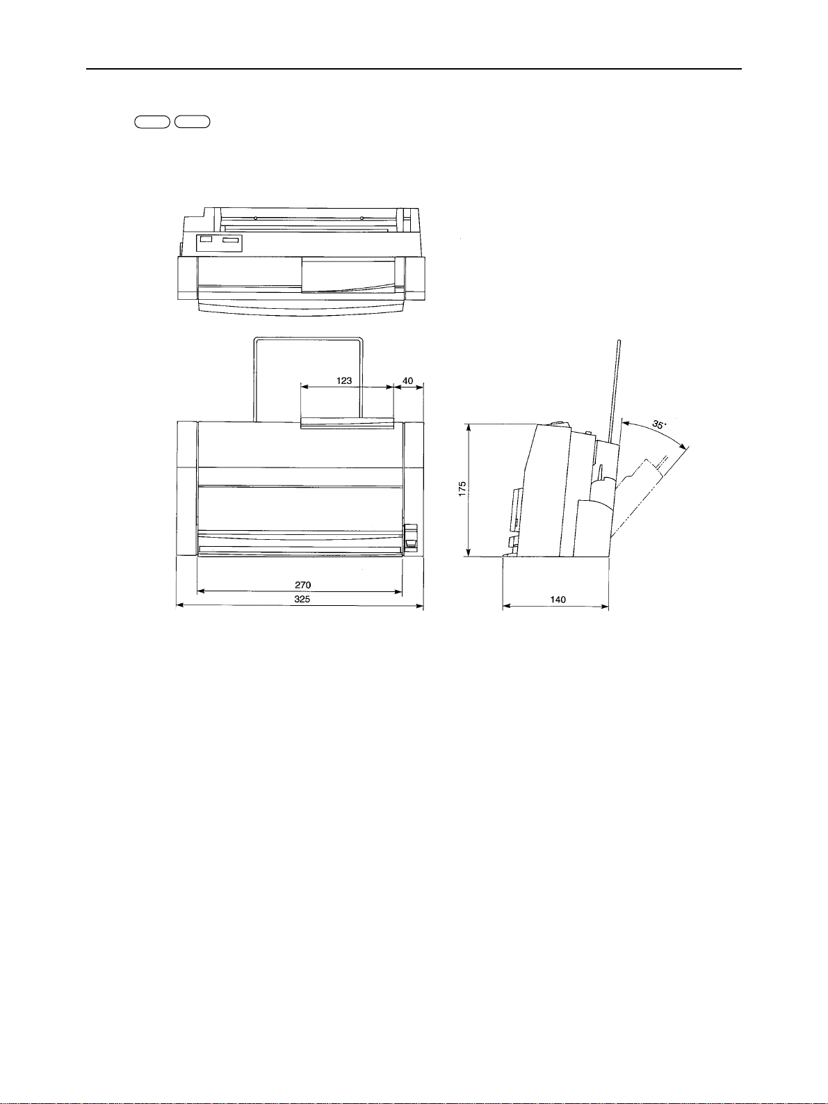
Dimensions and Weight
MACPC
Width 325 mm (12.8")
Depth 140 mm (5.5")
Height 175 mm (6.9")
Weight 2.5 kg (5.5 lbs)
AC adapter power supply 100 ~ 120 VAC, 220 ~ 240 VAC, 50/60Hz
MACPC
(varies according to the country of purchase)
– 4 –

GENERAL SPECIFICATIONS
Options
PC
MAC
Ink ribbon cartridge for plain paper
T144BK (Sold in 3 pack) Type: Monochrome ribbon (one time use)
Life: 345,000 characters (12CPI, 6 LPI)
180 pages/cartridge (1500 characters per page)
Length: 340 m
Width: 12.7 mm
T144CL (Sold in 3 pack) Type: Color ribbon (one time use)
Life: 8.0 pages per cartridge (8.0" × 9.6" Full graphics per page.)
Length: 193 cycles, 210 m
Width: 12.7 mm
Ink ribbon cartridge for overhead
projection (OHP) film
T144BKO Type: Monochrome ribbon (one time use)
Life: 200,000 characters (10CPI, 6LPI)
100 pages/cartridge (1500 characters per page)
Length: 200 m
Width: 12.7 mm
T144CLO Type: Color ribbon (one time use)
Life: 10.5 pages per cartridge (8.0" × 9.6" Full graphics per page.)
Length: 257 cycles, 270 m
Width: 12.7 mm
Ink ribbon cartridge for strip labels Type: Single color printing on single color background
125 labels per cartridge (1.8 inches per label)
Maximum label length: 7.2" (printable)
Strip label height: 0.5"
Background Color Printing Color
T01SL Transparent Black
T02SL White Black
T03SL Red Black
T04SL Blue Black
T05SL Green Black
T06SL Yellow Black
T07SL Gold Black
T08SL Silver Black
T31SL Transparent Red
T32SL White Red
T41SL Transparent Blue
T42SL White Blue
– 5 –
GENERAL SPECIFICATIONS
MACPC
Fig. 1-1 External Dimensions
– 6 –
GENERAL SPECIFICATIONS
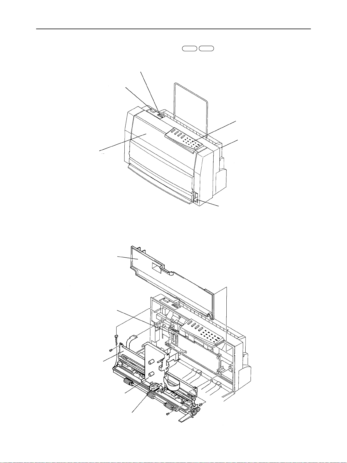
2. External Appearance and Composition
Print density Dial
Power Switch
Front Cover
MACPC
Control Panel
ASF Ass’y
Release Lever
Board Cover
Main Logic Board
Printer Mechanism
Fig. 1-2 Front View of the Printer
Carriage
Print Head
Fig. 1-3 Diagram of Internal Composition
– 7 –
GENERAL SPECIFICATIONS
3. Control Panel
3-1. Switch Combination Functions
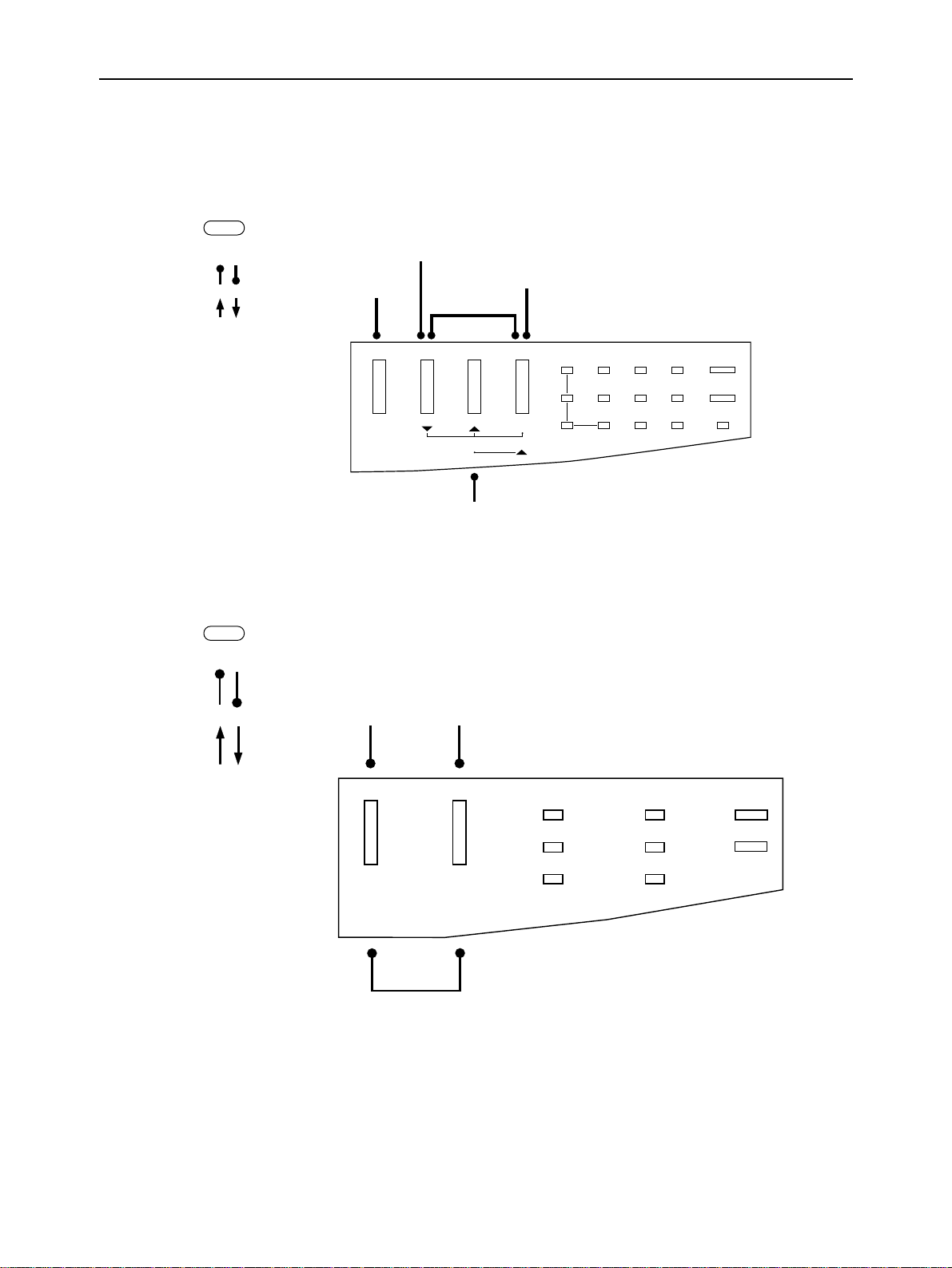
1) At power on
PC
Hold
Push
EDS mode
Hexadecimal dump
Short test (Color test)
LF adjustment
MAC
Hold
Push
Zoom Paper Ready
ALT Macro 2-Page Clear
Micro Freed
FF
Zoom AEC Color Paper Power
80%
CDM OHP Ribbon Ready
67%
2-Page Label Macro Data
50%
Long test
Fig. 1-4 Switch combination functions at power-on
Self-test1 Self-test1
COLOR
PAPER READY
OHP
PAPER
POWER
READY
RIBBON
LABEL
Adjustment mode
Fig. 1-5 Switch combination functions at power-on
– 8 –
DATA
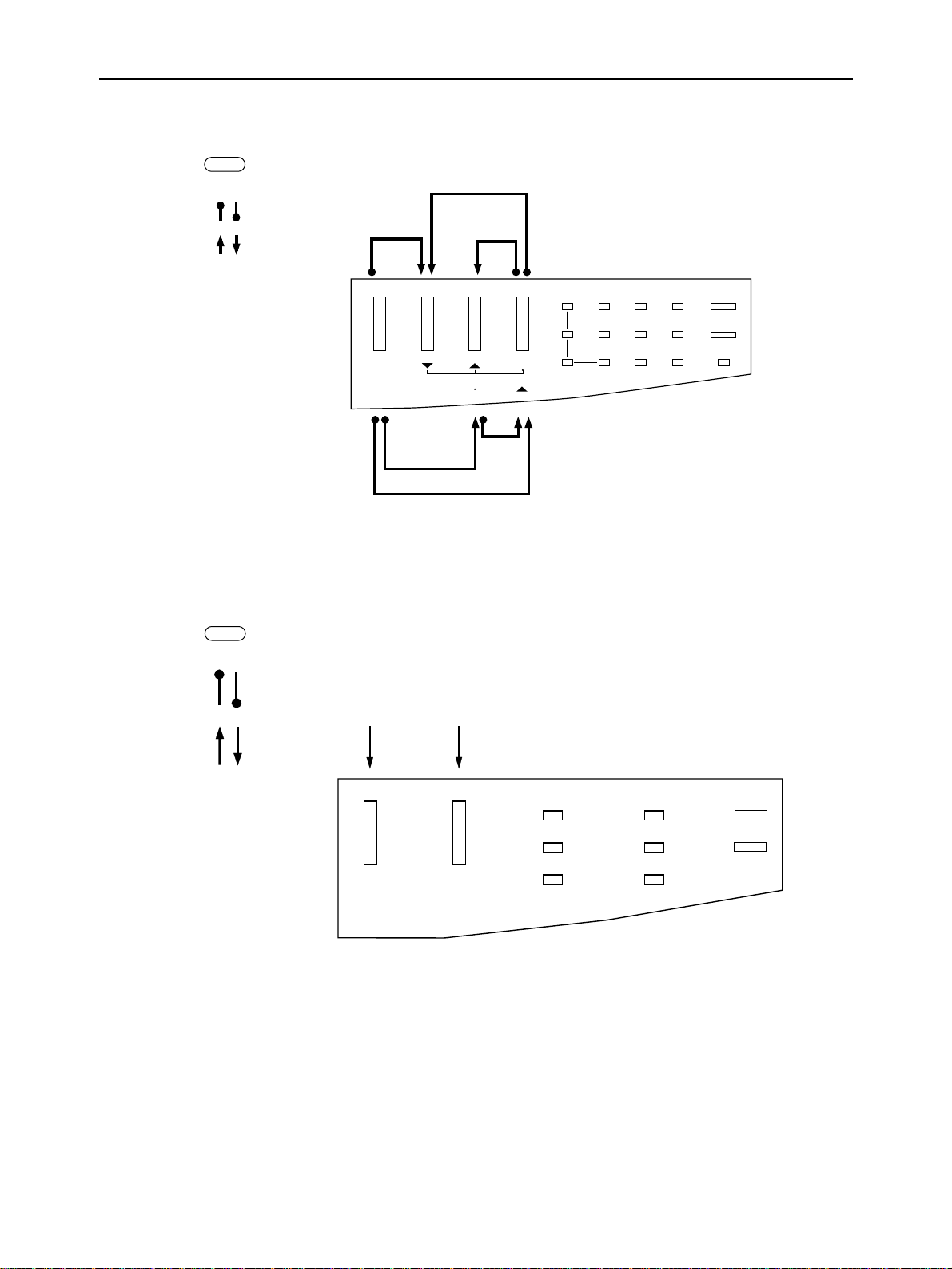
2) At off line
GENERAL SPECIFICATIONS
PC
Reverse micro-feed
MAC
Hold
Push
Saving macro
definition
ALT Macro 2-Page Clear
Forward
micro-feed
Zoom Paper Ready
Micro Freed
FF
Zoom AEC Color Paper Power
80%
CDM OHP Ribbon Ready
67%
2-Page Label Macro Data
50%
Paper
eject
2-Page mode
Cleaning the buffer/All reset
Fig. 1-6 Switch combination functions at off-line
Hold
Push
Sets printer on-linePaper feed/Feed
COLOR
PAPER READY
OHP
LABEL
Fig. 1-7 Switch combination functions at off-line
PAPER
POWER
READY
RIBBON
DATA
– 9 –
GENERAL SPECIFICATIONS
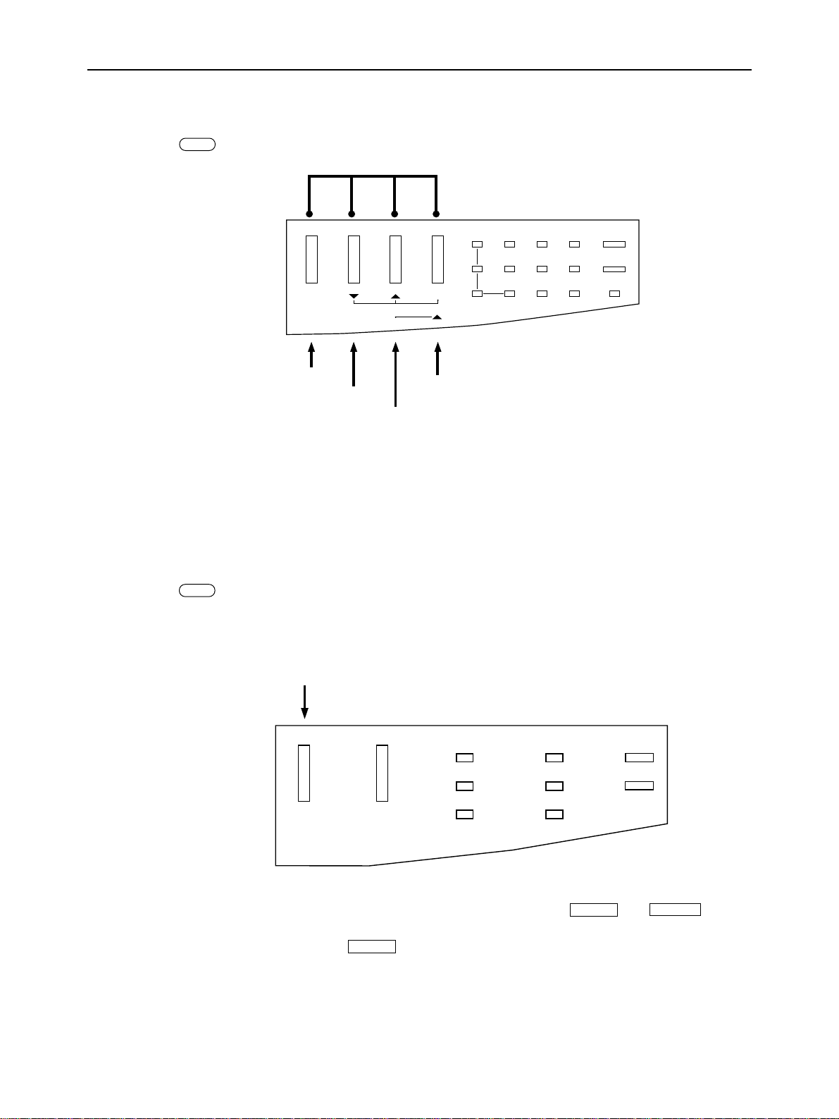
3) At power on (adjustment mode)
PC
Adjustment mode
Zoom Paper Ready
ALT Macro 2-Page Clear
LF adjustment
AN rotation printing
EE-PROM data dump
Micro Freed
FF
EE-PROM data reset
Zoom AEC Color Paper Power
80%
CDM OHP Ribbon Ready
67%
2-Page Label Macro Data
50%
[1]Turn the power on (press the power switch) while holding down the four buttons. The printer enters
adjustment mode.
[2]When in adjustment mode, pressing any one of the four function buttons will activate the appropriate function.
Refer to chapter 3 for further information.
Fig. 1-8 Adjustment mode
MAC
When a plain paper or OHP ribbon (monochrome or color) is installed, the printer
prints the factory-default pattern.
COLOR
PAPER READY
OHP
LABEL
[1]Turn the power on (by pressing the power switch) while holding down the
The printer enters adjustment mode.
In adjustment mode, pressing the
PAPER
button activates the function mentioned above.
Fig. 1-9 Adjustment mode
PAPER
RIBBON
DATA
PAPER
POWER
READY
and
READY
buttons.
– 10 –
GENERAL SPECIFICATIONS
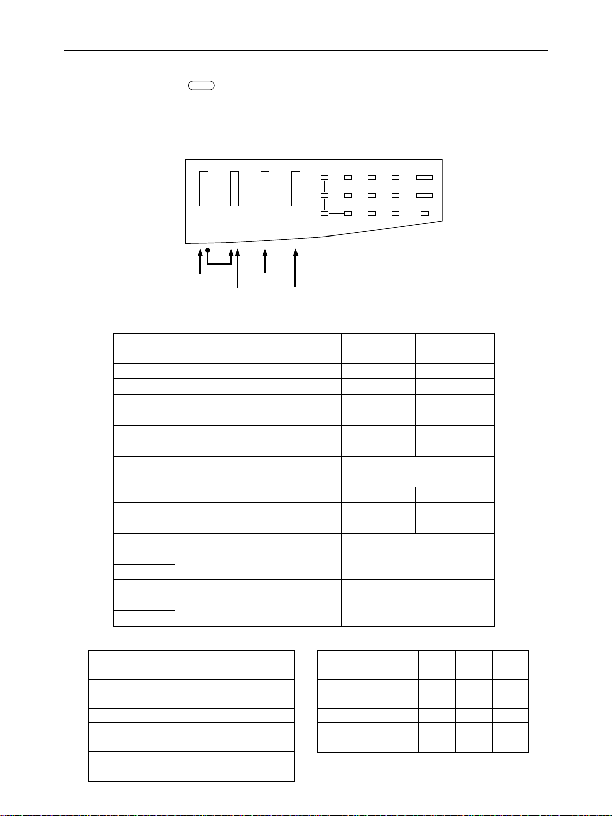
3-2. EDS Mode Settings
PC
The EDS (Electronic DIP Switch) mode in the printer has 12 functions that you can set as the power-on default.
Turn the printer ON while holding down the ALT button. One of the Zoom lamps will blink to indicate that you have
entered the EDS mode.
In EDS mode, the buttons on the control panel are used as shown below in Fig. 1-7.
Zoom Paper Ready
ALT Macro 2-Page Clear
Exit
Select Bank
Select Switch
Print
Change Setting
Zoom 1 4
A
B
C
25
3 6 On/Off
Fig. 1-10 Button and indicator functions in the EDS mode
Bank Switch Function ON OFF
A-1 Emulation Standard/Epson IBM
A-2 Auto Emulation Change (AEC) mode Enabled Disabled
A-3 RAM usage Input buffer Download buffer
A-4 Ribbon save mode Enabled Disabled
A-5 Time out paper eject Enabled Disabled
A-6 Page length Letter/11" A4/11.7"
B-1 Auto LF with CR Disabled Enabled
B-2 (Not used)
B-3 (Not used)
B-4 Font selection Roman H-Gothic
B-5 Epson character table Graphics Italics
B-6 IBM character table IBM #2 IBM #1
C-1
C-2 International character set (See table below)
C-3
C-4
C-5 IBM Code Page (See table below)
C-6
Country C-1 C-2 C-3
U.S.A. ON ON ON
France OFF ON ON
Germany ON OFF ON
England OFF OFF ON
Denmark I ON ON OFF
Sweden OFF ON OFF
Italy ON OFF OFF
Spain I OFF OFF OFF
IBM Code Page C-4 C-5 C-6
#437 U.S.A. ON ON ON
#850 Multi-lingual OFF ON ON
#860 Portuguese ON OFF ON
#861 Icelandic OFF OFF ON
#863 Canadian French ON ON OFF
#865 Nordic OFF ON OFF
– 11 –
GENERAL SPECIFICATIONS
4. Parallel Interface
PC
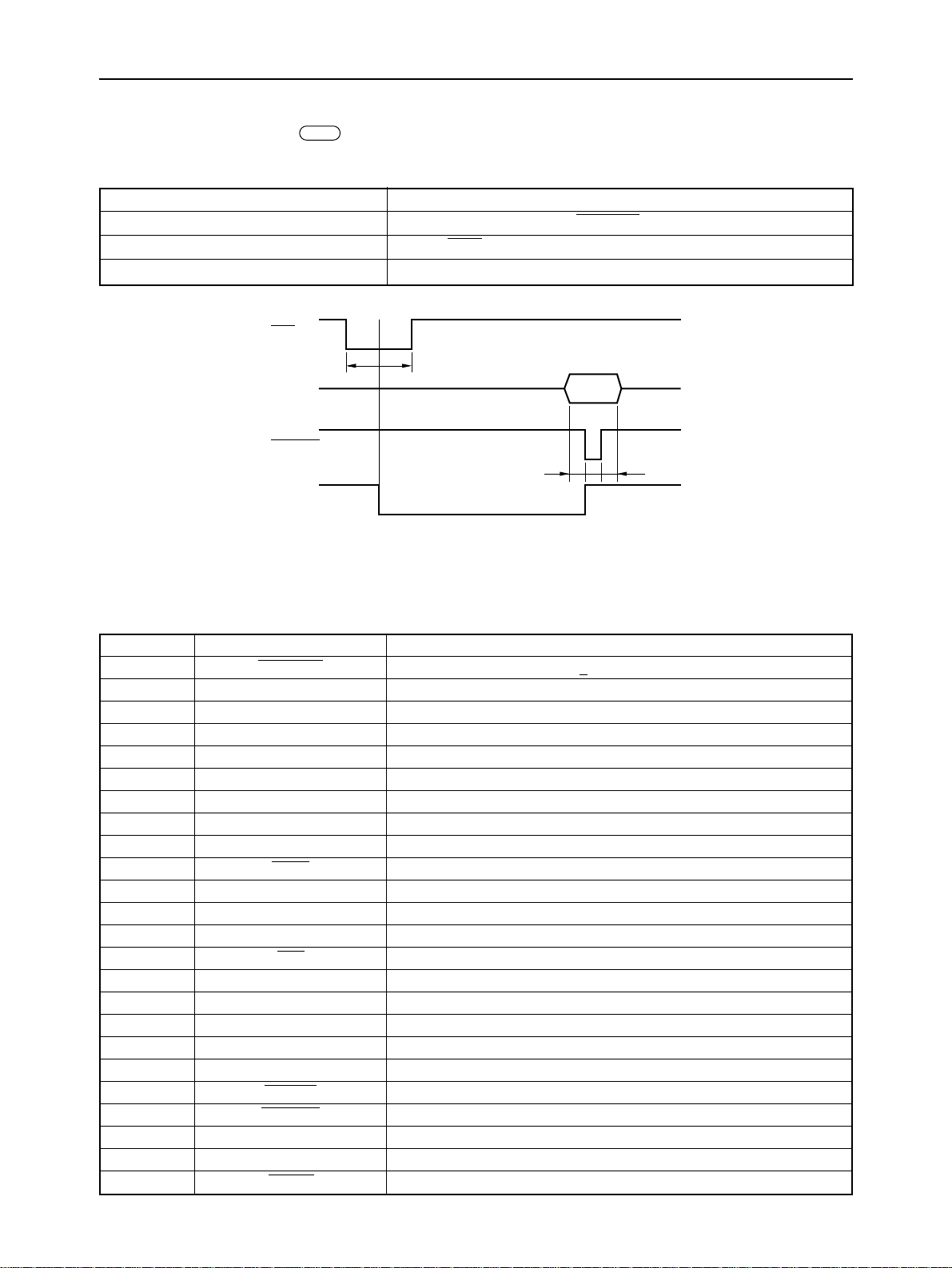
4-1. General Specifications
Item Specifications
Synchronization System Via externally supplied STROBE pulse
I/F Protocol By ACK and BUSY signals
Logic Level Compatible with TTL level
ACK
5µs5µs
Data
STROBE
BUSY
T: More than 0.5µs
Fig. 1-11 Timing Charts of Parallel Interface
T
TT
4-2. Connector Signals
Pin No Signal Name Function Description
1 STROBE Goes from high to low (for≥ 0.5µs) when active.
2 DATA0 High when active.
3 DATA1 High when active.
4 DATA2 High when active.
5 DATA3 High when active.
6 DATA4 High when active.
7 DATA5 High when active.
8 DATA6 High when active.
9 DATA7 High when active.
10 ACK 10µs low pulse acknowledges receipt of data.
11 BUSY Low when printer ready to receive data.
12 PAPER OUT High when paper out.
13 SELECT High when printer is on-line.
14 AF0 Unused.
15 NC Unused.
16 SIGNAL GND Signal ground.
17 CHASSIS GND Chassis ground.
18 +5V +5V DC output from printer (Max. 40 mA)
19 ~ 30 GND Twisted pair ground return.
31 RESET When this input signal is low, printer is reset.
32 ERROR Outputs low when printer cannot continue, due to an error.
33 SIGNAL GND Signal ground.
34 ~ 35 NC Unused.
36 SELIN Unused.
– 12 –
GENERAL SPECIFICATIONS
5. Serial interface
Transmission method
Standard : RS-422 Serial
•
• Transmission system : all dual
• Transmission speed : 57,600 bps
• Deviation : +0.23%
Data format
Data length : 8 bits
•
• Start bit : 1 bit
• Stop bit : 1 bit
• Parity bit : none
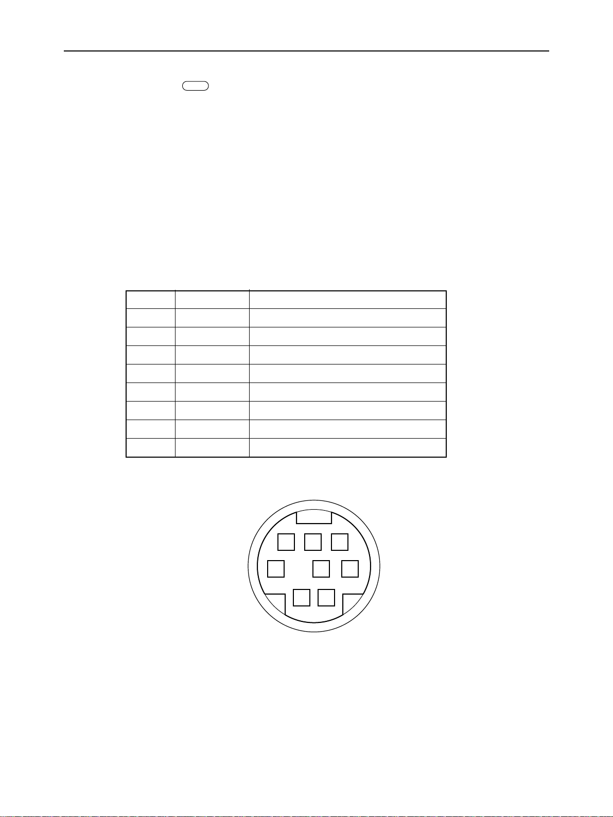
Connector
Mini Din serial port connector or equivalent
•
Pin Signal name Description
1 OPEN
2 OPEN
3 TxD – Data transmitted from the printer (negative)
4 GND Ground potential for all data
MAC
5 RxD – Data transmitted to the printer (negative)
6 TxD + Data transmitted from the printer (positive)
7 OPEN
8 RxD + Data transmitted to the printer (positive)
678
543
12
Fig. 1-12 Connector pin specifications
– 13 –

GENERAL SPECIFICATIONS
– 2 –

CHAPTER 2
THEORY OF OPERATION
This chapter explains the principles of the electric circuits and the mechanisms.
1. Block Diagram .....................................................................................................17
2. Main logic Board .................................................................................................19
2-1. Parallel Interface....................................................................................................... 19
2-2. Serial interface input/output circuit .................................................................... 20
2-3. General Flow Chart ............................................................................................... 21
2-3-1. Editing ............................................................................................................... 22
2-3-2. Print Head Drive Circuit................................................................................... 22
2-3-3. Motor Driving Circuit........................................................................................ 23
3. Power Supply Circuit ..........................................................................................24
2
4. Mechanism...........................................................................................................25
4-1. Printing Mechanism.............................................................................................. 25
4-1-1. Identification of Ribbon/Label Cartridge........................................................ 26
4-1-2. Feature for Pressing Head and Reeling Ink Ribbon...................................... 27
4-1-3. Ribbon Detector ............................................................................................... 30
4-2. Print Head Carrying Mechanism ......................................................................... 30
4-3. Paper Feed Mechanism........................................................................................ 31
4-3-1. Routes of Paper Sheet Passage ..................................................................... 31
4-3-2. Paper Support and Release............................................................................. 32
4-3-3. Paper End Detector.......................................................................................... 32
4-3-4. Auto Loading Detector..................................................................................... 33

THEORY OF OPERATION
– 16 –
THEORY OF OPERATION
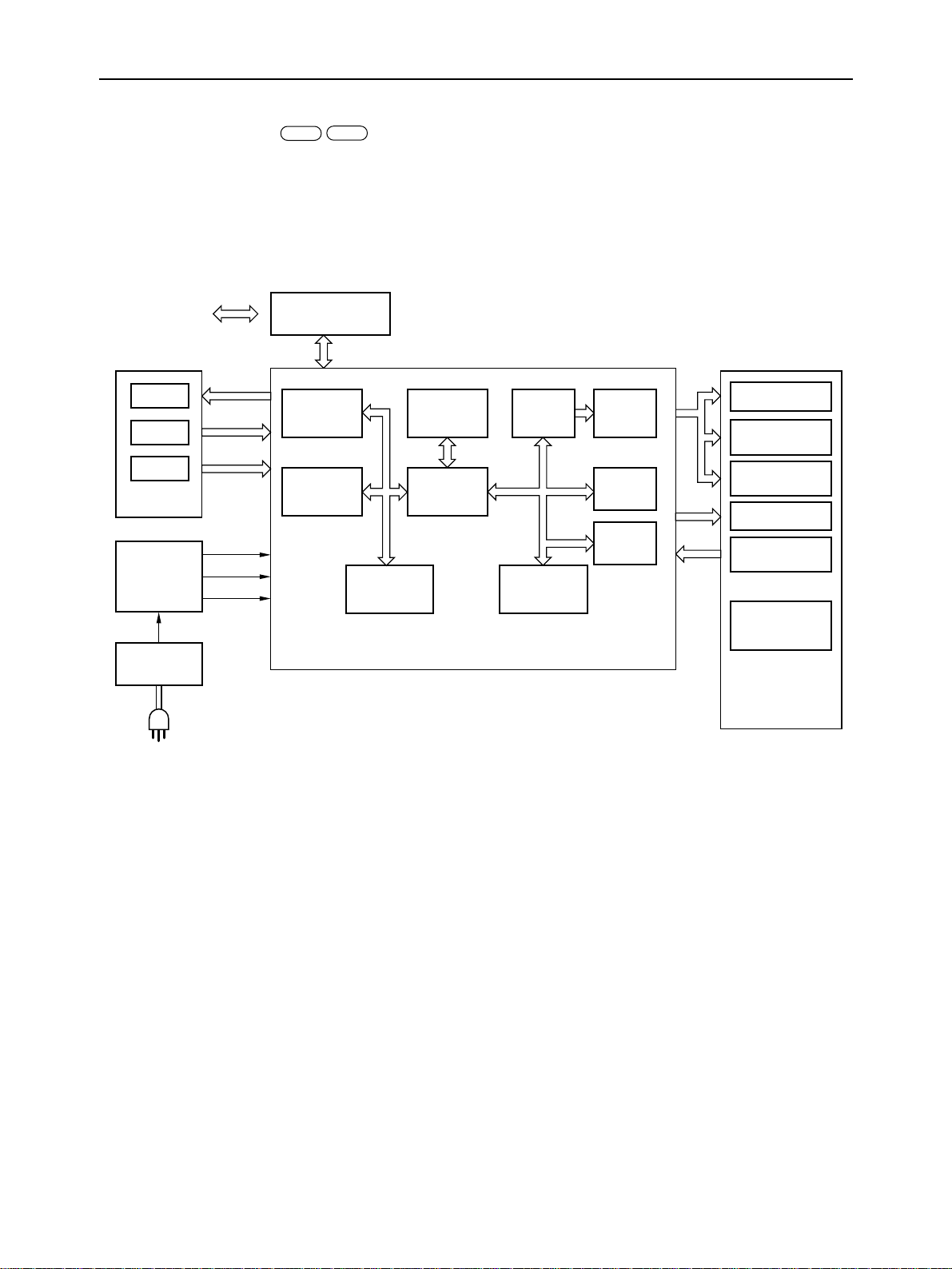
1. Block Diagram
MACPC
The block diagram of this printer is shown in Fig. 2-1.
Data
(From computer)
Lamp
Switch
Detector
Control
Panel Board
DC/DC
Converter
24VDC
AC Adapter
I/F Connector
Unit
Parallel
Interface
Masked
ROM(IC7)
28~40VDC
24VDC
5VDC
(Interface PC : Parallel MAC : Serial)
(Masked ROM IC3 and IC7 PC : 78k II, V25 MAC : 78k II MC, V25MC)
RAM
(IC24,25)
(IC6)
CPU
(IC5)
Main Logic Board
LSI
LSI
(IC2)
CPU
(IC1)
Motor
Driver
ETCC
(IC4)
Masked
ROM(IC3)
Carriage Motor
Paper Feed
Motor
Ribbon Feed
Moter
Print Head
Detectors
Automatic
Sheet Feeder
Fig. 2-1 Block Diagram
Printer
Machanism
– 17 –

THEORY OF OPERATION
(1) Main Logic Board
This board receives the data from the computer and stores it in the RAM in the order of arrival. The CPU on this
board reads the data from the RAM, and edits it according to the program stored in the masked ROM.
When the editing is completed, various drive signals from the CPU are sent to the printer mechanism to perform
printing.
<Explanation>
1. CPU uPD78213 (IC 1)
Carries out most of printer mechanism control, and emulations control.
2. CPU uPD70325 (IC 5)
Controls the character font and parallel interface.
3. LSI ETCC (IC 4)
Controls the thermal compensation for the print head.
4. LSI uPD91316 (IC 2)
Carries out motor control and part of printer mechanism control.
5. LSI uPD65640 (IC 6)
Controls the RAMs (IC24 and IC25).
(2) Control Panel Board
This board is provided with LEDs which display the operating condition of the printer and control switches which
are used to set each mode.
(3) Printer Mechanism
The printer mechanism consists of a print head, carriage motor, paper feed motor, ribbon feed motor, detectors, and
automatic sheet feeder.
(4) AC Adapter
Converts AC voltage into 24 VDC.
(5) DC/DC Converter
Converts 24 VDC into 28 to 40 VDC, and 5 VDC for the logic circuit.
– 18 –
THEORY OF OPERATION
2. Main logic Board
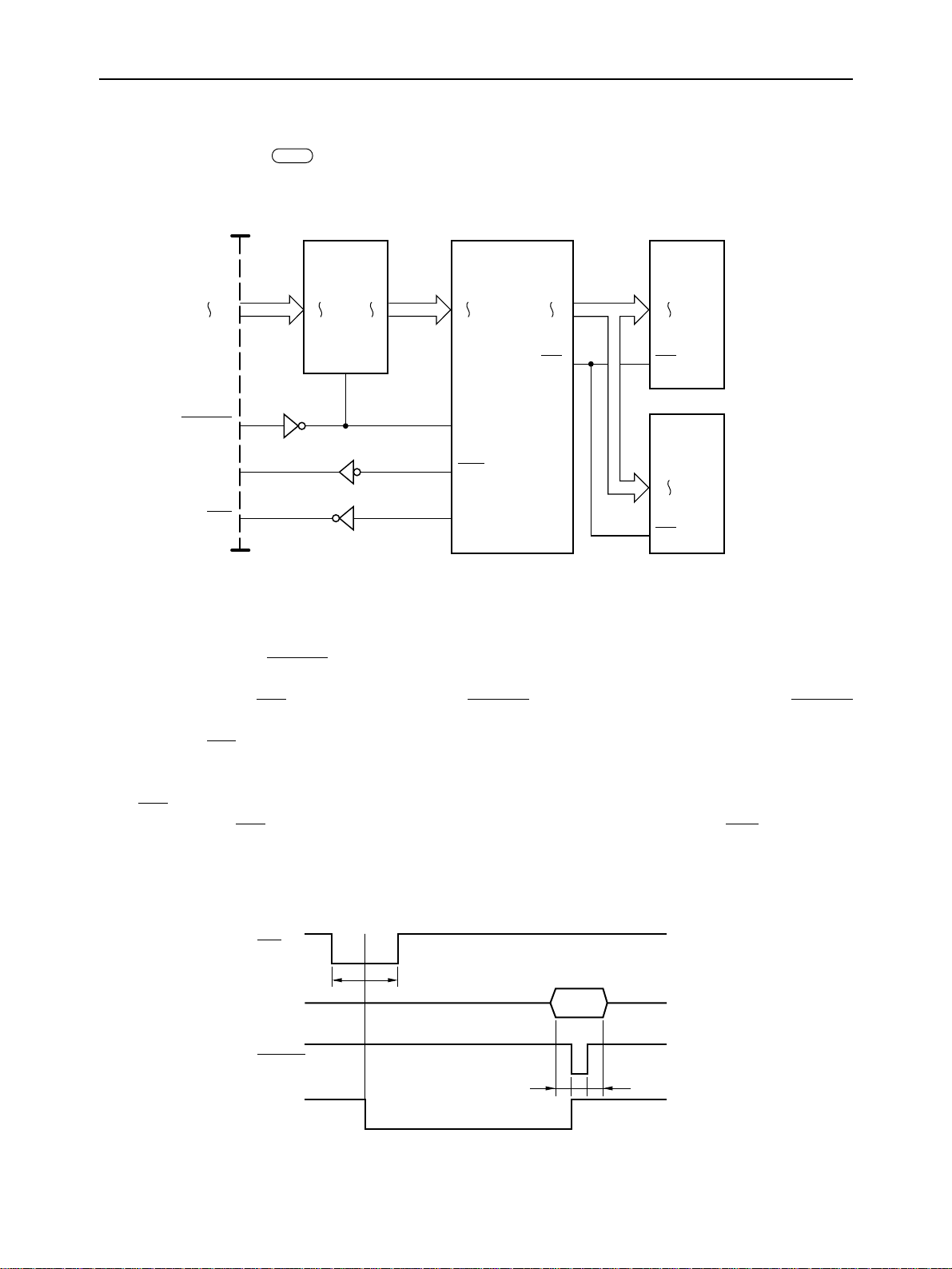
2-1. Parallel Interface
Communications between the computer and this printer are facilitated via parallel interface. The circuit of this interface
is shown in Fig. 2-2.
CN6
PC
DATA 0
DATA 7
STROBE
BUSY
ACK
IC18
LS373
D1
D8
Q1
Q8
EN
D0
D7
STB
BSY
ACK
IC6
CPU
MD0
MD8
WE
IC24
RAM
IO1
IO4
WE
IC25
RAM
IO1
IO4
WE
Fig. 2-2 Data Input Circuit with Parallel Interface
The following is an explanation of this handshake.
(1) When the BUSY signal is LOW (Ready), the computer outputs 8-bit data 0 through 7 to the connector CN6. The
computer carries the STROBE pulse signal to the printer. This signal is normally held HIGH by the computer. When
the computer has data ready for the printer, it sets this signal to LOW for at least 0.5 µs.
(2) The CPU turns the BSY signal LOW at the fall of the STROBE signal. IC18 latches data at the rise of the STROBE
signal.
(3) When the BSY signal goes LOW, the BUSY signal through connector CN6 turns HIGH, and the computer is
informed that the printer cannot receive data.
(4) The CPU reads in data from IC 18 for storage in the RAM. When the reading-in is completed, the CPU turns the
BSY and ACK signals HIGH.
(3) When both the BSY and ACK signals output from the CPU turn HIGH, both the BUSY and ACK signals output
through connector CN6 go LOW, and the computer is informed that the printer can receive data and sends the
following data to the printer.
ACK
Data
STROBE
BUSY
5µs5µs
TT
T: More than 0.5µs
Fig. 2-3 Timing chart of Parallel Interface
– 19 –
T
THEORY OF OPERATION
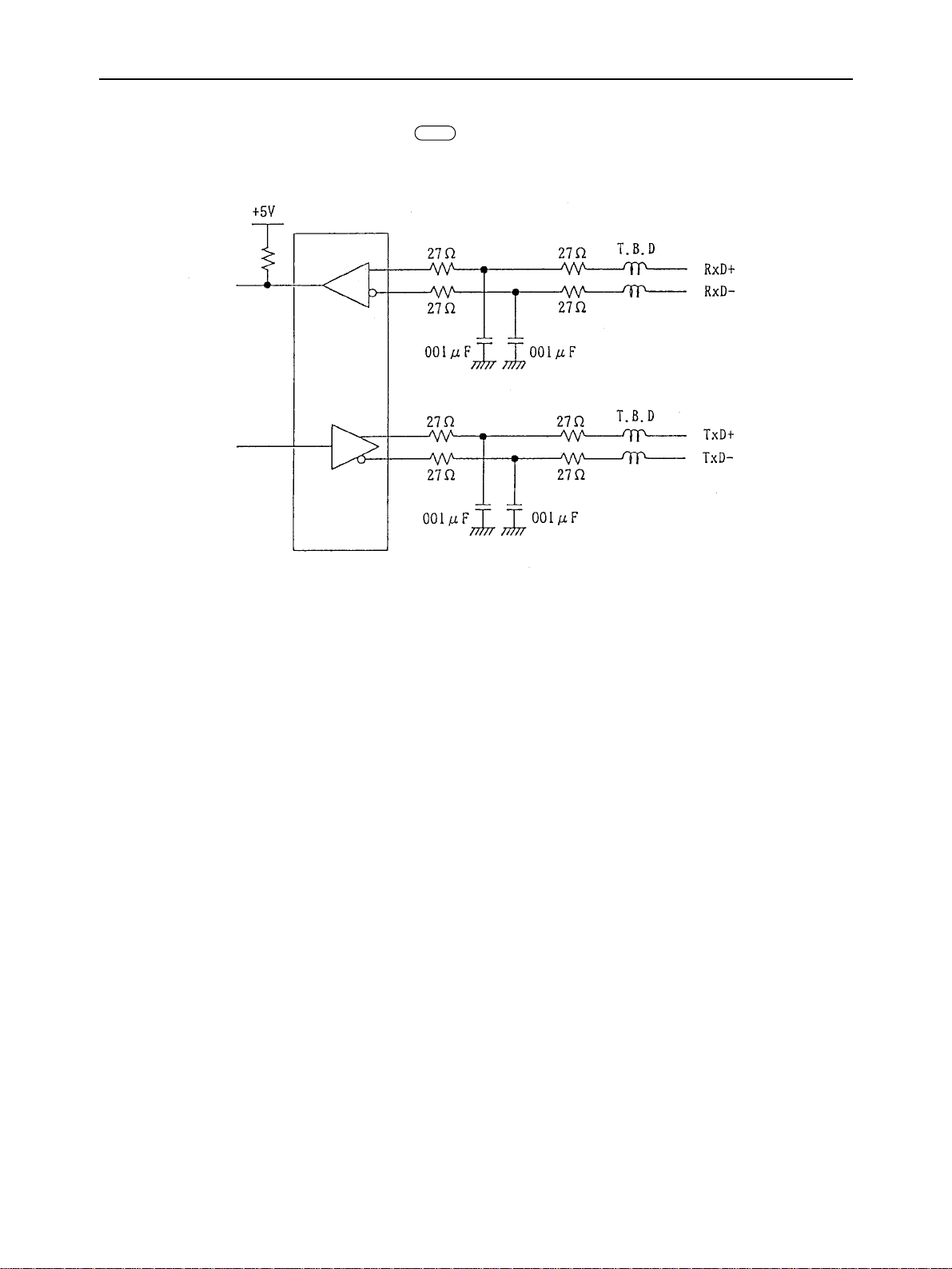
2-2. Serial interface input/output circuit
To CPU port
From CPU port
IC26
MAC
Fig. 2-4 Input/output circuit
IC26 is an RS-422 driver/receiver equipped with an internal transformer which can generate from the +5V power supply
the ±2~5V necessary for RS-422 output. Thus it can convert between RS-422C and TTL signals. Data transmitted by the
host computer is input to the CPU from RXD via IC26. The serial data input to the CPU is converted to parallel data in
the CPU, then output to the main logic board. Conversely, parallel data is converted to serial data in the CPU and output
on TXD via IC26.
– 20 –
THEORY OF OPERATION
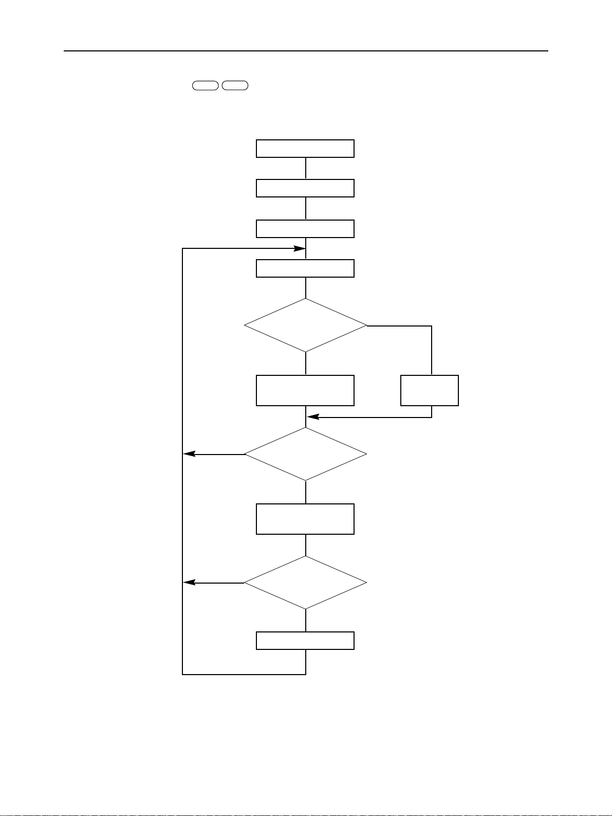
2-3. General Flow Chart
PC
MAC
A general flow chart of editing and printing operations are presented in Fig. 2-5.
POWER ON
Initialization
Ready State
Read Data
Control Code?
NO
YES
NO
NO
Control Code
Processing
Print?
YES
Data Processing
or Printing
Return?
YES
Return Action
Data
Storage
(Line buffer detemination)
(Print out of data)
Fig. 2-5 General Flow Chart of Editing and Printing
– 21 –
THEORY OF OPERATION
2-3-1. Editing
PC
Data stored in the RAM is read out sequentially by the CPU and then edited according to a function code that has been
specified in advance.
This editing takes places until the line buffer becomes full.
MAC
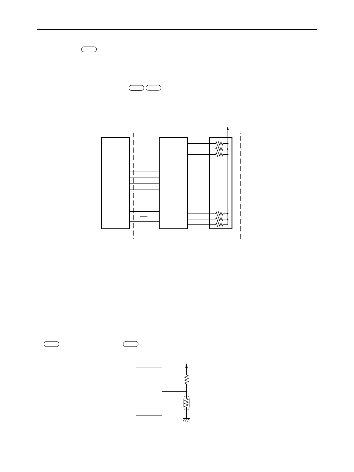
2-3-2. Print Head Drive Circuit
PC
The print head contains 144 heating resistor elements. Data is printed by switching ON and OFF each of the elements.
The print head also incorporates a driver with a data latch function.
IC4 (ETCC) functions as a thermal head controller. It sends 18 bytes of data in units of 8 bits (8 bits × 18 bytes = 144
bits) to the head driver as one row of data in sync with the HCLK signal.
HD1
HD2
HD3
HD142
HD143
HD144
IC4
ETCC
HEN
HD0
HD1
HD2
HD3
HD4
HD5
HD6
HD7
HCLK
HLT
Driver
Vhd (28~40V)
Main Logic Board Print Head
Fig. 2-6 Print Head Drive Circuit
• Printing density depends on the heat accumulated on the print head, the ambient temperature, the ink ribbon type and
the dispersion of the thermal print head resistance. IC4 controls the printing energy by changing the heat energizing
period in accordance with data such as the heat accumulated on the print head, ambient temperature and the ink ribbon
type, to provide the optimum print density. To provide against the dispersion of the thermal print head resistance, DC/
DC converter controls print head voltage Vhd. This control process is explained in “Power Supply Circuit” in item
3.
The heat accumulated on the print head is determined by reading past data of energizing a specific heating resistor
element (whether the element is energized over the last 1-4 dots) and past data records of the adjacent elements (whether
the elements are energized over the last 1-3 dots).
• Ambient temperature is measured by the ambient temperature detection circuit in the control panel unit for the
????? and the carriage unit for the ??????. The circuit reads the voltage divided by the 10 kΩ resistor and the thermistor
MACPC
at analogue input port PT2 of the CPU, and the CPU calculates the temperature on the basis of the read voltage.
+5V
R148
PT2
IC5
CPU
Thermistor
Fig.2-7 Ambient temperature detection circuit
• Ink ribbon types are identified depending on whether each of the three cassette switches is turned ON or OFF, to detect
the type of the ribbon cartridge or the label cartridge set on the carriage unit.
– 22 –
THEORY OF OPERATION
MAC
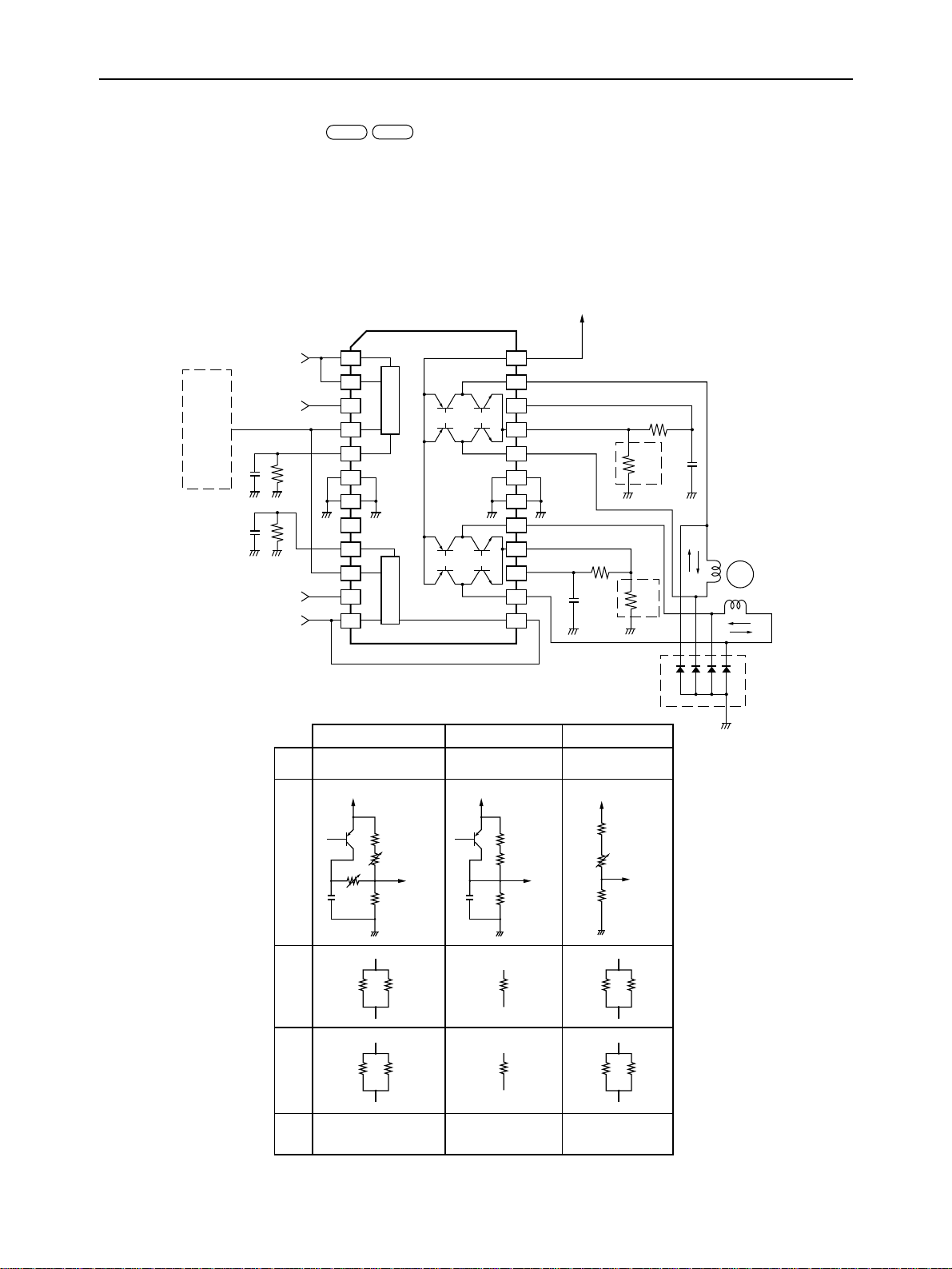
2-3-3. Motor Driving Circuit
The carriage motor, the paper feed motor and the ribbon feed motor are implemented as bipolar-type pulse ones. Any
of their drive circuits is based on chopper-type constant current control.
The three motor drive circuits have the same configuration, and employ driver ICs (UDN2916) as their main parts. The
three circuits are different in reference voltage VREF, current detection resistance RS and use of diodes. The diodes are
used to prevent the motor and driver IC (UDN2916) from generating heat.
Current IO through the motor is calculated by the following equation:
IO =K × VREF/RS
where, K: constant
PC
+24V
UDN 2916
Control 3
Control 1
V
REF
Control 0
Control 2
1
2
3
4
5
6
7
8
5V V
9
10
11
12
CC
PWM 2PWM 1
24
23
2
22
21
20
S
R
19
18
17
1
16
15
14
R
13
ø3
ø2
S
M
ø1
ø0
Diode
Carriage Motor Paper Feed Motor Ribbon Feed Motor
IC IC11 IC10 IC12
+5V
+5V
+5V
TR5 TR11
REF
V
R
S1
R
S2
Diode
R226
VR3
VR4
R228
Mounted Not mounted Mounted
Fig. 2-8 Motor Driving Circuit
R217
REF
V
R222R265 R213 R261R267
R224R266 R215
R219
REF
V
– 23 –
R256
VR5
R258
REF
V
R263R268
THEORY OF OPERATION
MAC
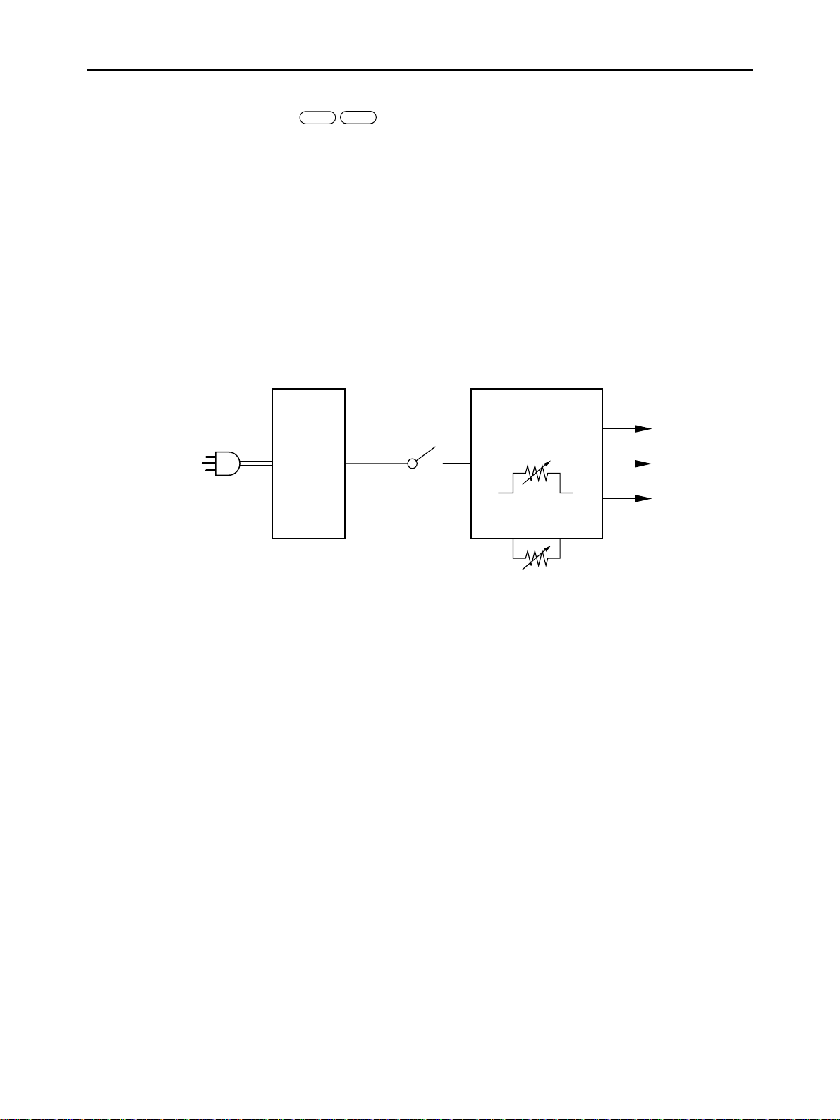
3. Power Supply Circuit
Commercial AC voltage is converted into 24 VDC by an AC adaptor. The voltage of 24 VDC is converted into three types
of DC voltage by the DC/DC converter unit. These three types of DC voltage are 5 volts for the control circuit, and 24
volts for motor, and 28 to 40 voltages for the print head.
The voltage applied for the print head is variable from 28 to 40 VDC using potentiometers for printing density adjustment
VR1 and for the head rank VR2.
Potentiometer VR1 can be controlled by turning the printing density dial by the user. Potentiometer VR2 functions to
compensate for the dispersion of the thermal print head resistance in accordance with the resistance of the thermal print
head.
For adjusting the potentiometers, see Item 1 in Chapter 3.
PC
100~120VAC
220~240VAC
AC
Adapter
24VDC
Power Switch
Fig. 2-9 Power Supply Circuit
DC/DC
Converter
VR2
VR1
5VDC
24VDC
28~40VDC
– 24 –
THEORY OF OPERATION
4. Mechanism
MACPC
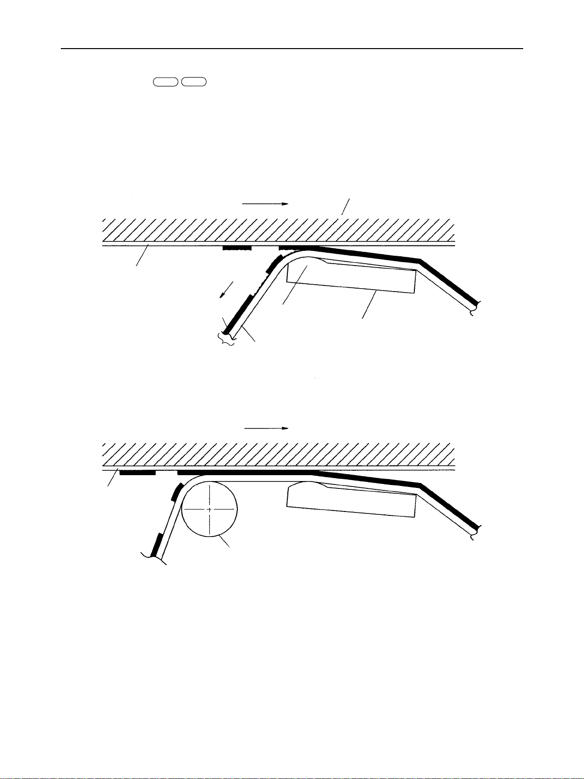
4-1. Printing Mechanism
The printing mechanism is composed of a print head, an ink ribbon and a platen incorporated in a carriage unit. The print
head is of a thermal type, comprising a ceramic board provided with 144 heating elements. Applying current to and heating
the thermal head melts ink on the ink ribbon (film ribbon) for transcription onto a paper sheet. An ink ribbon for an OHP
is such that the roller comes by the side of the thermal head to delay the timing at which the ink ribbon is pulled off a OHP
film.
Printing for Plain Paper, Label
Platen
Printing Direction
Paper or Label
Ribbon Reel
Ink
Ink Ribbon
Heating Element
Thermal Head
Base Film
Printing OHP Film
OHP Film
Printing Direction
Roller
Fig. 2-10 Principle of thermal transcription strategy
– 25 –
THEORY OF OPERATION
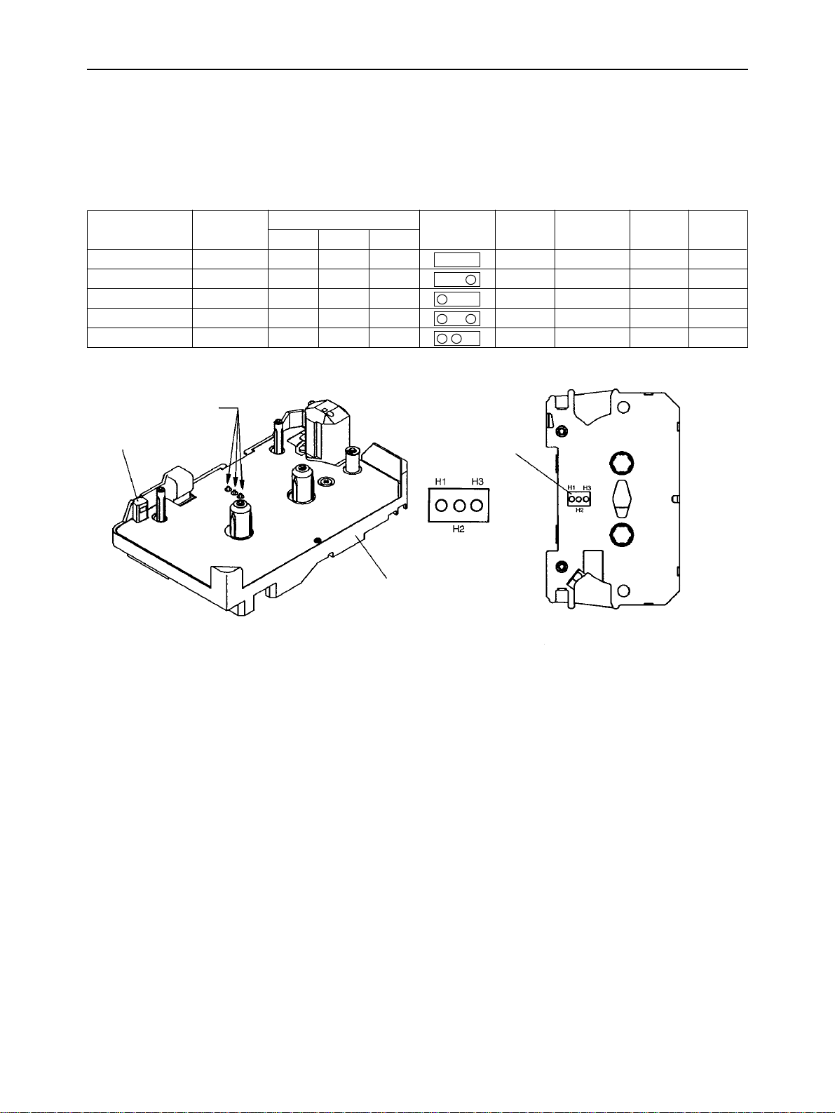
4-1-1. Identification of Ribbon/Label Cartridge
The ribbon cartridge and the label cartridge are holed for type identification. The carriage unit is provided with three
cassette switches (three pins) for sensing this hole. The pins play a role as a switch to identify the type. Depending on
the type, a number of factors are varied which include the carriage speed, the period of energizing the print head, pressing
force and the timing at which the ink ribbon is pulled off the paper sheet.
Ribbon/Label Type
OHP Monochrome
OHP Color
Color
Monochrome
Label
Cassettl Switch
Ribbon Detector
Print Media
OHP Film
OHP Film
Paper
Paper
Itself
Holes
H1 H2 H3
Closed Closed Closed
Closed Closed Opened
Opened Closed Closed
Opened Closed Opened
Opened Opened Closed
Carriage Unit
View
Hole for cartridge
Identification
Carriage
Head energiz-
Speed
Low
Low
High
High
Low
ing period
Long
Long
Long
Short
Longest
Bottom View of Ribbon/
Label Cartridge
Pressing
force
High
High
Low
Low
High
Pulling
timing
Slow
Slow
Fast
Fast
Fast
Fig. 2-11 Identification of ribbon/label cartridge
– 26 –
 Loading...