

Page 1
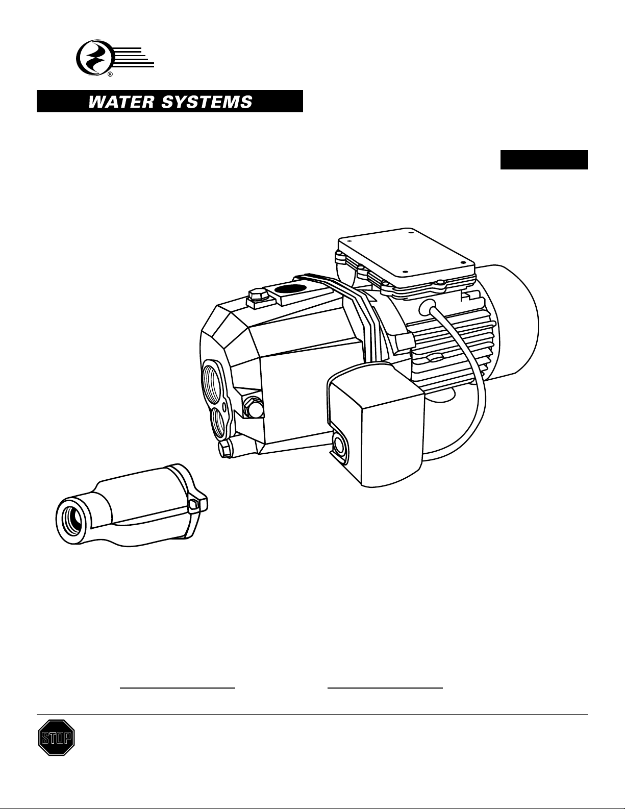
MODEL SJ05 1/2 HP, SJ07 3/4 HP, SJ10 1 HP
STAR
®
DEEP WELL 2 PIPE
CONVERTIBLE JET PUMP
Español p. 23
ATTACH YOUR RECEIPT HERE
Serial Number Purchase Date
Questions, problems, missing parts? Before returning to your retailer, call our customer
STOP
service department at 1-800-742-5044, 7:30 a.m. - 5 p.m., EST, Monday - Friday.
1
95 North Oak Street • Kendallville, IN 46755 • © 2014 Star Water Systems. All rights reserved.
SW0900 A
Page 2
TABLE OF CONTENTS
Product Specications ......................................................................................................................2
Safety Information ............................................................................................................................2
Package Contents ............................................................................................................................4
Preparation .......................................................................................................................................5
General Pump Information ...............................................................................................................5
Well to Pump Connection .................................................................................................................7
Pump to Tank Connection ..............................................................................................................13
Tank to House Connection .............................................................................................................14
Pump Electrical Connections..........................................................................................................15
Pump Priming and Startup .............................................................................................................17
Care and Maintenance ...................................................................................................................19
Troubleshooting ..............................................................................................................................20
Warranty .........................................................................................................................................21
Replacement Parts .........................................................................................................................22
PRODUCT SPECIFICATIONS
Power supply required ...........................................................................115 volts or 230 volts, 60 Hz
(Pump is set by the factory to run on 230 volts)
Maximum water temperature ...........................................................................................77°F (25°C)
Individual branch circuit required ............................................................................ 15 Amp minimum
Discharge connection .......................................................................................................... 1 in. NPT
Suction connection ........................................................................................................1-1/4 in. NPT
Motor duty..................... Continuous duty with enforced air cooling and thermal overload protection
Pressure switch ........................................................................... Preset at 20 PSI “on” / 40 PSI “off”
Water depth rating ................................................................................................. Maximum of 40 ft.
CAPACITY - U.S. GALLONS PER MINUTE
AT 20 PSI DISCHARGE PRESSURE (PSI)
ITEM # HP VOLTAGE HZ AMP
SHALLOW WELL DEEP WELL
5 FT. 15 FT. 25 FT. 30 FT. 40 FT.
SJ05 1/2 115/230 60 8.0/3.9 8.5 6.0 3.5 7.0 6.5
SJ07 3/4 115/230 60 10.9/5.4 10.0 8.0 4.5 8.5 6.8
SJ10 1 115/230 60 10.9/5.4 13.0 10.0 5.5 10.0 7.0
SAFETY INFORMATION
Please read and understand this entire manual before attempting to assemble, operate or install the
product.
2
95 North Oak Street • Kendallville, IN 46755 • © 2014 Star Water Systems. All rights reserved.
Page 3
SAFETY INFORMATION
DANGER
ELECTRICAL SHOCK HAZARD.
Always disconnect power source before performing any work on or near the motor or its
connected load. If the power disconnect point is out-of-sight, lock it in the open position
and tag it to prevent unexpected application of power. Failure to do so could result in
fatal electrical shock.
ELECTRICAL SHOCK HAZARD.
Do not handle the pump with wet hands or when standing in water as fatal electrical
shock could occur. Disconnect main power before handling unit for ANY REASON!
RISK OF ELECTRIC SHOCK.
These pumps have not been investigated for use in swimming pool areas.
WARNING
ELECTRICAL SHOCK ALERT.
Follow all local electrical and safety codes, as well as the National Electrical Code (NEC) and
the Occupational Safety and Health Act (OSHA).
ELECTRICAL SHOCK ALERT.
Replace damaged or worn wiring cord immediately. Never use an extension cord.
ELECTRICAL SHOCK ALERT.
Do not kink power cable and never allow the cable to come in contact with oil, grease, hot
surfaces, or chemicals.
ELECTRICAL SHOCK ALERT.
Wire motor to correct supply voltage. See motor nameplate and wiring diagrams and check
voltage of power supply.
ELECTRICAL SHOCK ALERT.
Unit must be securely and adequately electrically grounded. This can be accomplished by
wiring the unit to a ground metal-clad raceway system or by using a separate ground wire
connected to the bare metal of the motor frame or other suitable means.
ELECTRICAL SHOCK ALERT.
Do not disassemble the motor housing. This pump has no repairable internal parts and
disassembling may cause leakage or dangerous electrical wiring issues.
ELECTRICAL SHOCK ALERT.
Make certain the electrical power source is adequate for the requirements of the pump.
ELECTRICAL SHOCK ALERT.
Never use an extension cord with this pump.
CHEMICAL ALERT.
This product contains chemicals known to the state of California to cause cancer and birth
defects or other reproductive harm.
HAZARDOUS PRESSURE ALERT.
Install pressure relief valve in discharge pipe. Release all pressure on system before working
on any component.
EXPLOSION ALERT
Do not use to pump ammable or explosive uids such as gasoline, fuel oil, kerosene, etc.
Do not use in ammable and/or explosive atmospheres.
3
95 North Oak Street • Kendallville, IN 46755 • © 2014 Star Water Systems. All rights reserved.
Page 4
SAFETY INFORMATION
CAUTION
PRODUCT DAMAGE MAY RESULT
This pump is not to be used for irrigation or water systems.
PRODUCT DAMAGE MAY RESULT
Protect the power cable from coming in contact with sharp objects.
PRODUCT DAMAGE MAY RESULT
Do not run pump dry.
PRODUCT DAMAGE MAY RESULT
Pump and plumbing must be full of water before startup.
PRODUCT DAMAGE MAY RESULT
Do not pump water which contains sand, mud, silt, or debris.
INJURY MAY RESULT
Be careful when touching the exterior of an operating motor. It may be hot enough to be painful or
cause injury.
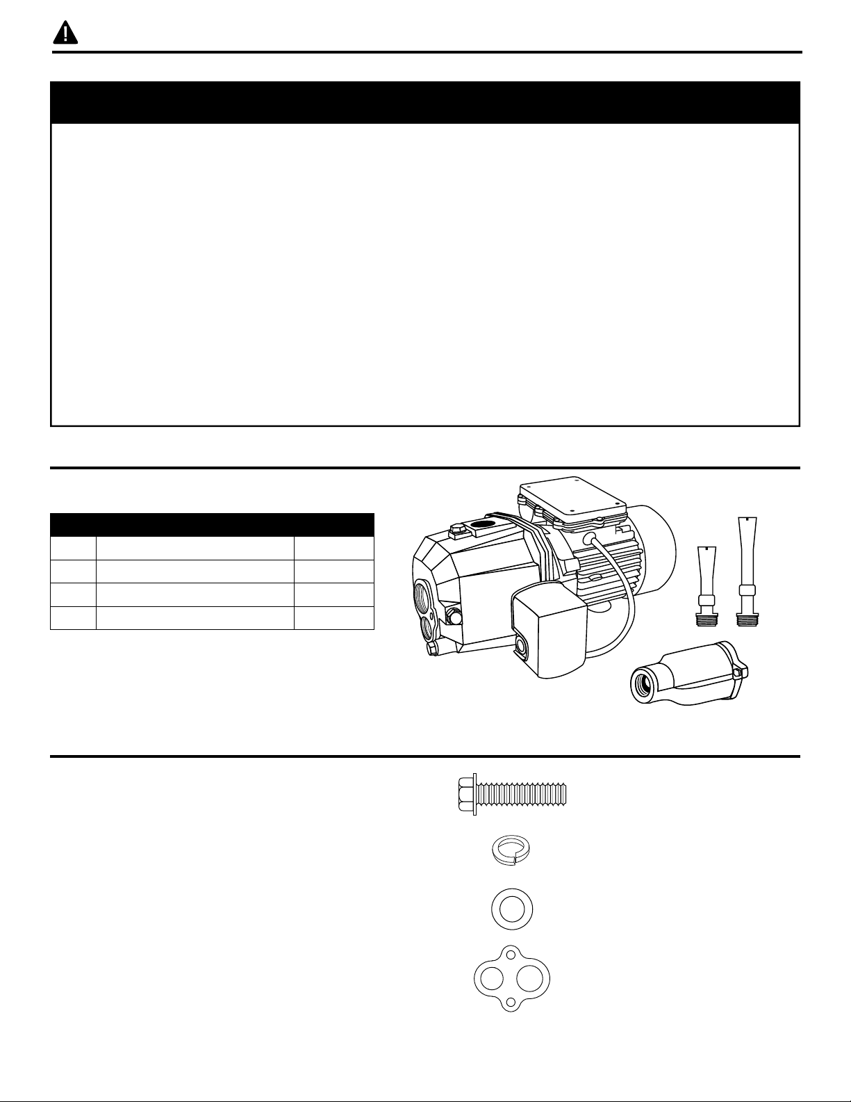
PACKAGE CONTENTS
Part Description Quantity
1 Pump 1
2 Ejector 1
3 Short Venturi Tube 1
4 Long Venturi Tube 1
HARDWARE CONTENTS (not shown actual size)
A 3/8 x 1-NC Hex Bolt
B 3/8 LW
x 2
x 2
C Flat Washer
D Gasket
4
95 North Oak Street • Kendallville, IN 46755 • © 2014 Star Water Systems. All rights reserved.
x 2
x 1
Page 5
PREPARATION
Before beginning installation of product, make sure all parts are present. If any part is missing or
damaged, do not attempt to assemble the product. Compare parts to package contents list and
hardware contents list.
Estimated Installation Time: 2 hours.
Tools Required for Assembly (not included): pipe wrench, pliers, Phillips screwdriver, pipe clamp, 2-step
PVC glue system (primer and sealer), thread tape
Parts Required for Assembly (not included): 1-1/4 in. to 1 in. male PVC adapter, 1-1/4 in. male PVC
adapter, 1 in. male PVC adapter, 1 in. foot valve, 1-1/4 in. PVC pipe, 1 in. PVC pipe, 1-1/4 in. PVC
elbow, 1 in. PVC elbow, 1 in. discharge tee, galvanized bushing, pressure gauge or pipe plug, electrical
wire strain relief (2), 1 in. close nipple, 1 in. x 5 in. pipe nipple
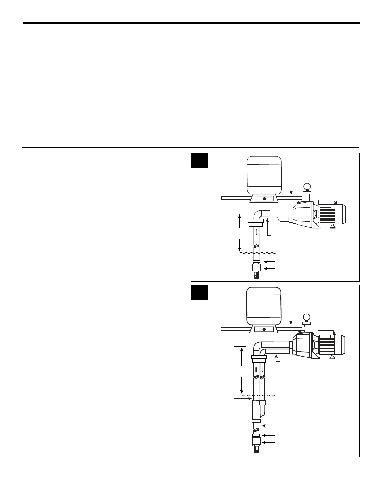
GENERAL PUMP INFORMATION
Typical Pump Setup
Convertible jet pumps are designed for use in
these applications:
1. Shallow wells (0 - 25 ft. lift) where ejector bolts
to pump.
2. Deep wells (0 - 40 ft. lift) where well inside
diameter is 4 in. or more and ejector is
installed in the well.
1
2
Discharge
to
Home
Suction
Lift
25 ft.
Max.
Discharge
to
Home
1 in.
Discharge Pipe
1 in.
Suction Pipe
Water Level
1-1/4 in. x 1 in. Male Adapter
1-1/4 in. Foot Valve
1 in.
Discharge Pipe
Suction
Lift
1 in.
40 ft.
Max.
1-1/4 in.
Suction Pipe
5
95 North Oak Street • Kendallville, IN 46755 • © 2014 Star Water Systems. All rights reserved.
Pressure Pipe
Water Level
1 in. Pipe
1 -1/4 in. to 1 in. Male Adapter
1-1/4 in. Foot Valve
Page 6
GENERAL PUMP INFORMATION
Ventilation - Ventilation and drainage must be provided to prevent damage to the motor from heat
and moisture.
Freezing - Pump and all piping must be protected from freezing. If freezing weather is forecast, drain
pump or remove completely from the system.
Water Supply - The water source must be able to supply enough water to satisfy the capacity of
pump and water needs. See performance chart on page 2.
Suction Lift - Suction lift is the vertical distance from the lowest level of the water to the pump intake.
See performance chart on page 2.
Horizontal Distance - The horizontal distance is the horizontal measurement between pump suction
and the water source. This distance may affect the ability of pump to operate. If it is more than 100 ft.,
call the manufacturer for assistance 1-800-742-5044.
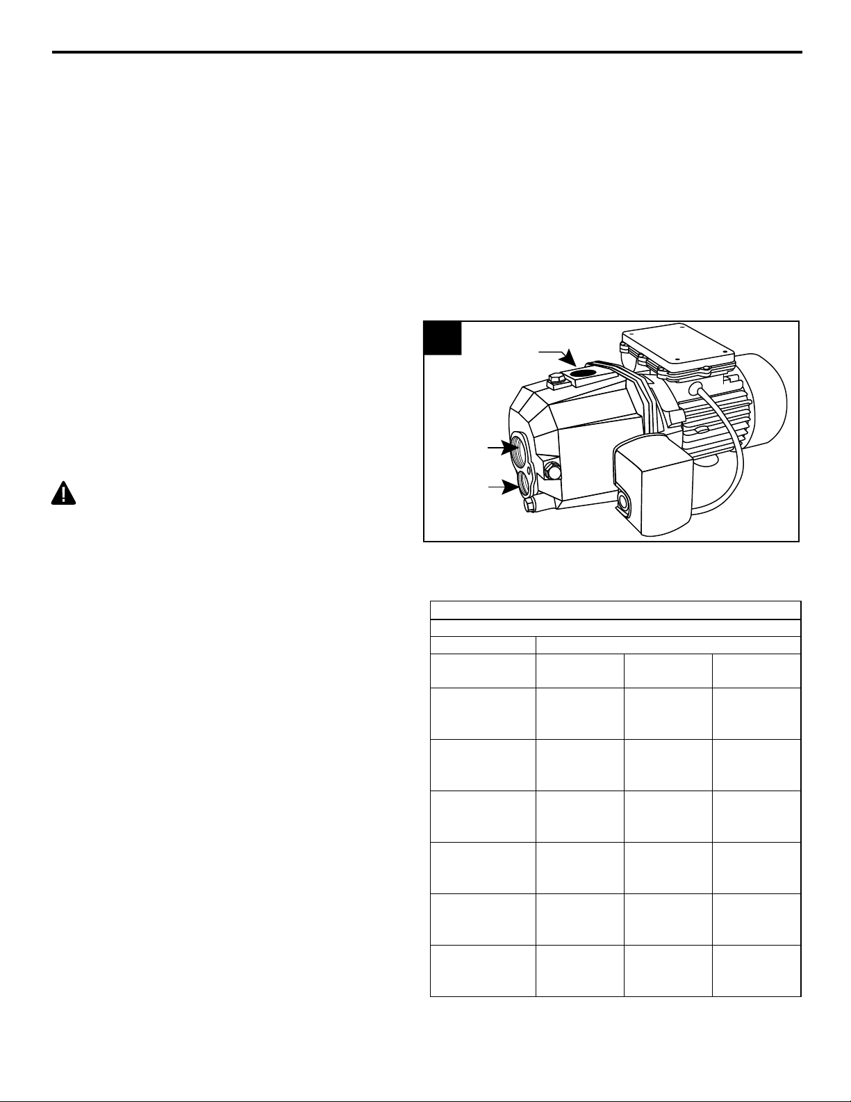
Pipe And Fittings
3. Use galvanized steel or NSF PW Schedule
40 PVC pipe and ttings. This material is
designed for water pressure and will seal
against air and water under pressure. Do
not use DWV ttings, as these are designed
for drains without pressure and will not seal
properly.
CAUTION: The entire system must be
air and water tight for efcient operation and to
maintain prime.
Wire Size:
The wire size is determined by the distance from
the power source to the pump motor and the
horsepower rating of the motor. See Table A for
proper wire size.
3
1 in. NPT
Discharge
1-1/4 in.
Suction
1 in.
Pressure
Pipe
Wire Size Chart - Table A
Recommended Copper Wire and Fuse Sizes
HP Rating of Single Phase Motors
Distance from
Motor to Meter
0-50’
115 V
230 V
50-100’
115 V
230 V
100-150’
115 V
230 V
150-200’
115 V
230 V
200-300’
115 V
230 V
Fuse Size
115 V
230 V
1/2 3/4 1
14 GA
14 GA
12 GA
14 GA
12 GA
14 GA
12 GA
14 GA
10 GA
14 GA
Amps
15
15
14 GA
14 GA
12 GA
14 GA
10 GA
12 GA
10 GA
12 GA
8 GA
10 GA
Amps
15
15
12 GA
14 GA
12 GA
14 GA
10 GA
12 GA
8 GA
12 GA
6 GA
10 GA
Amps
20
15
6
95 North Oak Street • Kendallville, IN 46755 • © 2014 Star Water Systems. All rights reserved.
Page 7
WELL TO PUMP CONNECTION (SUCTION PIPE)
CAUTION: Dry-t entire assembly to ensure proper t before gluing or taping parts.
CAUTION: Follow all proper gluing procedures as specied by the glue manufacturer. Always
glue in a vertical direction whenever possible to prevent glue from dripping inside pipe or ttings
CAUTION: Use pipe tape and pipe paste compound on all male threads. Tighten with wrench to
a snug t and add another 1/4 turn to ensure proper seal.
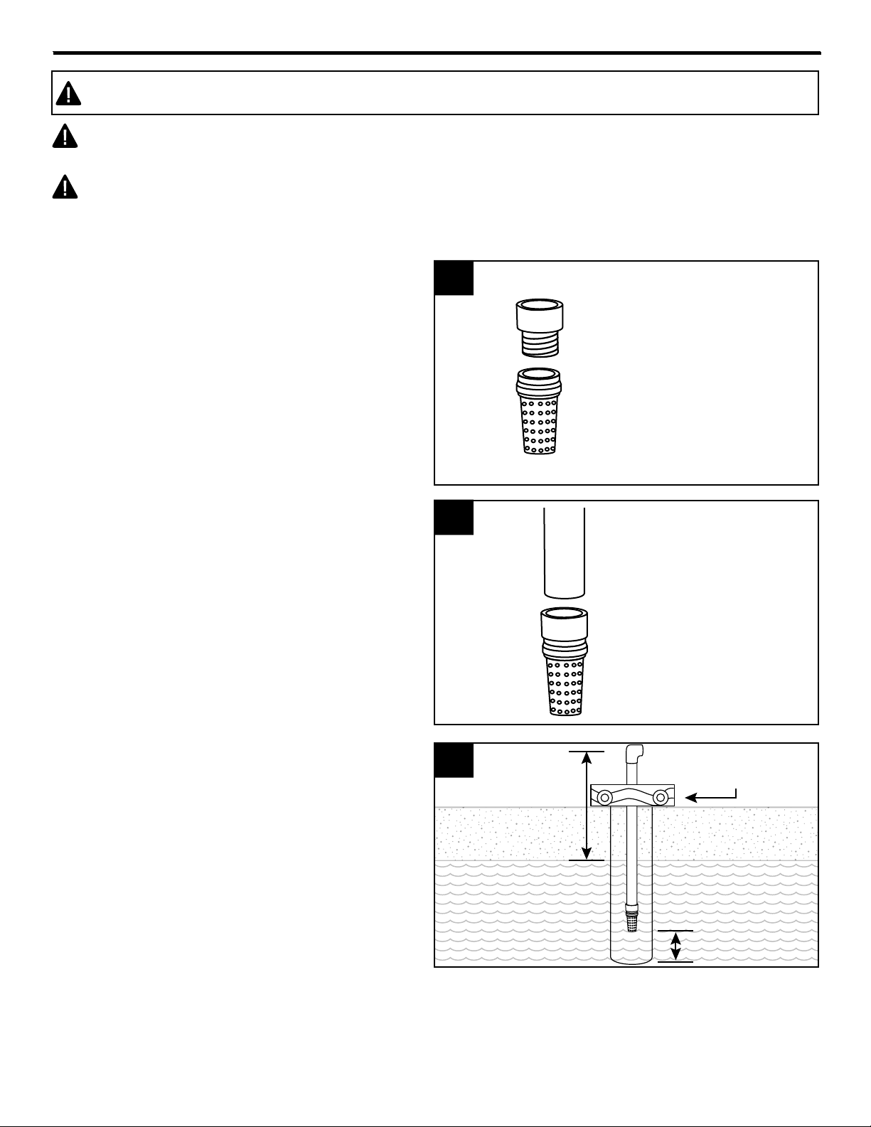
Shallow Well Installations Only
1. Thread 1-1/4 in. male x 1 in. PVC adapter
(not included) into a 1-1/4 in. foot valve (not
included). Hand tighten, then tighten 1/2 turn
with a pipe wrench.
2. Using a 2-step PVC system (not included),
attach enough PVC pipe and couplings to
the adapter to equal the depth of the well,
minus 5 ft.
1
1-1/4 in. male x 1 in.
PVC adapter
1-1/4 in. foot valve
2
1 in. PVC pipe
3. Before sliding the pipe assembly into the
well, rmly clamp the assembly with a pipe
clamp (not included) to prevent the assembly
from sliding down into the well.
95 North Oak Street • Kendallville, IN 46755 • © 2014 Star Water Systems. All rights reserved.
3
Pipe clamp
25 ft. maximum
Water level
5 ft. minimum
7
Page 8
WELL TO PUMP CONNECTION (SUCTION PIPE)
1-1/4 in.
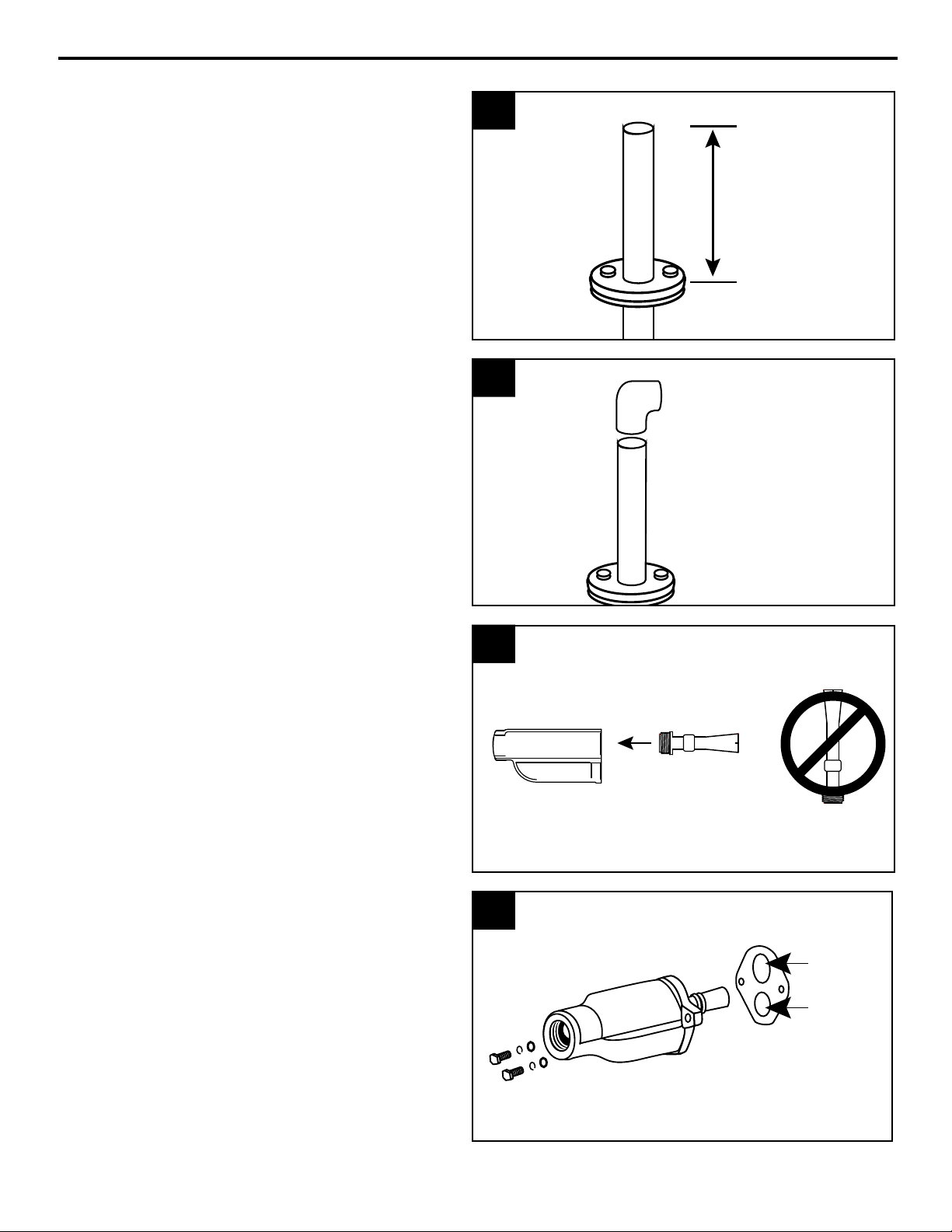
4. Remove the pipe clamp and slide a well seal
(not included) over the PVC pipe and onto
the well casing. The PVC pipe should extend
approximately 12 in. above the top of the well
seal, depending on the height of the pump.
NOTE: Do not let the assembly slide down into the
well. Tighten the well seal until the rubber gaskets
are tight against the well casing and the PVC pipe.
5. Using a 2-step PVC system, attach a 1 in. PVC
elbow (not included) onto the rigid PVC pipe
extending from the well seal.
4
Approx.
12 in.
Well Seal
5
1 in. PVC
Elbow
6. IMPORTANT: Use short venturi tube in ejector
body for shallow well applications. Do not use
long venturi tube. Ejector must be attached to
front of pump for shallow well applications.
7a. Place gasket against back of ejector so that
openings in gasket line up with openings
in ejector. Line up bolts, 3/8 LW and flat
washers with openings in ejector and slide
the bolts through the bolt opening.
6
Short
Long
7a
opening
1 in.
opening
8
95 North Oak Street • Kendallville, IN 46755 • © 2014 Star Water Systems. All rights reserved.
Page 9

WELL TO PUMP CONNECTION (SUCTION PIPE)
7b. Tighten bolts (AA) securely.
NOTE: The 1-1/4 in. opening in back of ejector
goes on top of pump and the 1 in. opening goes
on the bottom.
8. Wrap thread tape around the threads of a 1 in.
male PVC adapter (not included). Thread the
adapter into the front of ejector.
7b
8
1 in. Male
PVC adapter
9. Using 2-step PVC system, attach 1 in. PVC
pipe and couplings (not included) as needed to
connect the 1 in. male PVC adapter to the 1 in.
PVC elbow attached to the top of the well pipe
in Step 5.
NOTE: Be sure the pipe slopes downward slightly
from pump to the well to prevent air pockets.
Proceed to PUMP TO TANK CONNECTION
9
1 in. PVC Pipe
1 in. Male PVC
Adapter
Well
9
95 North Oak Street • Kendallville, IN 46755 • © 2014 Star Water Systems. All rights reserved.
Page 10

WELL TO PUMP CONNECTION (SUCTION PIPE)
Deep Well Installations Only
1. Wrap both ends of a 1 in. close nipple with
thread tape. Thread the close nipple into 1-1/4
in. male x 1 in. adapter and thread the adapter
into a 1-1/4 in. foot valve (all not included).
Thread the other end of close nipple into
bottom of ejector. Hand tighten, then tighten 1
turn with a pipe wrench.
2. IMPORTANT: For deep well applications, use
long venturi tube in ejector body. Do not use
short venturi tube in deep well applications.
NOTE: Hand-tighten only.
1
1 in. Close Nipple
1-1/4 in. Male x 1 in. Adapter
1-1/4 in. Foot Valve
2
Short
Long
3. Wrap thread tape around both ends of a 1 in.
x 5 in. nipple (not included) and thread the
nipple into the 1 in. opening in ejector. Hand
tighten, then tighten 1 turn with pipe wrench.
4. Wrap thread tape around threads of a 1-1/4 in.
male PVC adapter (not included) and thread
over long venturi tube and into ejector.
3
4
1 in. x 5 in. nipple
1 in. opening
1-1/4 in. male
PVC adapter
10
95 North Oak Street • Kendallville, IN 46755 • © 2014 Star Water Systems. All rights reserved.
Page 11

minimum
WELL TO PUMP CONNECTION (SUCTION PIPE)
5. Thread a 1 in. female PVC adapter (not
included) onto the 1 in. x 5 in. nipple. Hand
tighten, then tighten 1 turn with a pipe wrench.
6. Using a two step PVC system (not included)
attach enough couplings and rigid PVC pipe
(not included) to the adapters to equal the
depth of the well minus 5 ft.
5
6
1 in. female
PVC adapter
1 in. x 5 in.
nipple
7. Before sliding the pipe assembly into the well,
firmly clamp the assembly with a pipe clamp
(not included) to prevent the assembly from
sliding down into the well.
8. Remove the pipe clamp and slide well seal
over the PVC pipes and onto the well casing.
The PVC pipe should extend approximately
12 in. from the well seal, depending on the
height of the pump.
NOTE: Do not let assembly slide down into well.
Tighten the well seal until rubber gaskets are tight
against the well casing and the PVC pipes.
7
8
Pipe clamp
12 in.
40 ft.
maximum
Water level
5 ft.
PVC Pipes
Well Seal
Well Casing
11
95 North Oak Street • Kendallville, IN 46755 • © 2014 Star Water Systems. All rights reserved.
Page 12

1-1/4 in.
WELL TO PUMP CONNECTION (SUCTION PIPE)
9. Cut the 1 in. pipe 2 in. shorter than the 1-1/4
in. pipe. Smooth rough edges. Using a two
step PVC system, attach a 1 in. PVC elbow
(not included) and a 1-1/4 in. PVC elbow (not
included) to the pipes extending from the well
seal. Both elbows should face the pump.
10. Using a two step PVC system, attach
enough rigid 1 in. and 1-1/4 in. PVC pipe and
couplings to connect the pump to the 1 in.
and 1-1/4 in. elbows.
NOTE: Ensure the pipe slopes slightly toward the
well to prevent air pockets in the pipe.
9
10
2 in.
1-1/4 in. pipe
1-1/4 in.
Elbow
PVC elbow
1 in. PVC elbow
1 in. pipe
1-1/4 in.
PVC pipe
1 in. PVC pipe
1 in.
Elbow
Proceed to PUMP TO TANK CONNECTION
12
95 North Oak Street • Kendallville, IN 46755 • © 2014 Star Water Systems. All rights reserved.
Page 13

PUMP TO TANK CONNECTION (DISCHARGE PIPE)
1. Wrap thread tape (not included) around
threads of a 1 in. discharge tee (not included).
Using a pipe wrench, thread the 1 in.
discharge tee into the top of pump.
NOTE: To improve performance and consistency,
a flow control (not included) is recommended
for deep well applications in place of a standard
discharge tee. This will help regulate water
pressure fluctuations and may prevent loss of
prime.
2. Connect a 1 in. MPT x 1/4 in. FPT galvanized
bushing and pressure gauge (both not
included) or a pipe plug (not included) to the
discharge tee. Do not tighten, as you will
prime pump later at this location.
1
2
Pressure gauge
or pipe plug with
bushing
1 in. Discharge Tee
Discharge Tee
3. Wrap thread tape around the threads of a
1 in. male PVC adapter (not included) and
thread the adapter into the discharge tee.
4. Continue with ttings and pipe to the
pressure tank. A 1 in. union is optional but
recommended for easy connection and
disconnection.
3
1 in. male
PVC adapter
4
To pressure
tank
Discharge
tee
1 in. union
13
95 North Oak Street • Kendallville, IN 46755 • © 2014 Star Water Systems. All rights reserved.
Page 14

TANK TO HOUSE CONNECTION
1. Most pressure tanks will have a 1 in. inlet
elbow on the bottom. Connect to this elbow
with a 1 in. MPT x 1 in. slip (glue) adapter and
short piece of pipe.
2. Attach a 1 in. elbow (not included) to the pipe.
3
1
5
2
Adapter
Glue
Pipe
Elbow
3. Attach a 1 in. pipe (not included) to the elbow
and a 1 in. x 3/4 in. reducer bushing (not
included) to the pipe.
4. Attach a 3/4 in. pipe (not included) to the
reducer bushing. Install an optional 3/4
in. union (not included) and continue with
pipe and 3/4 in. x 3/4 in. x 3/4 in. tee (not
included).
3
4
Glue
1 in. x
3/4 in.
Reducer
Bushing
1 in. Pipe
Glue
Tee
Glue
Union
3/4 in. pipe
14
95 North Oak Street • Kendallville, IN 46755 • © 2014 Star Water Systems. All rights reserved.
Reducer
bushing
Page 15

TANK TO HOUSE CONNECTION
5. Attach the pipe from the pump to the tee
installed in Step 4. Then, from the tee,
install 3/4 in. pipe and optional shut off
valve (not included) to connect tee to
house plumbing.
6. IMPORTANT: Air pressure in the tank
must be 2 PSI lower than the “cut-in” of
the pressure switch. Pump has a 20/40
PSI pressure switch, so tank pressure
must be set at 18 PSI. Locate the air
valve/stem on the tank and check
pressure with a tire gauge (not included).
If air needs to be removed, press down on
valve to bleed off air. Use a tire pump or
air compressor to add air if needed.
5
From Pump
6
Air Valve/Stem
Glue
Shut off valve
To House
Plumbing
Tank
Tire gauge
PUMP ELECTRICAL CONNECTIONS
WARNING:
• Always disconnect pump from electricity before
performing any work on the motor.
• Under-sized wiring can cause motor failure and even
re. Use proper wire size specied in the Wire Size
Chart.
• Replace damaged or worn wiring cord immediately.
• Do not kink power cable and never allow the cable
to come in contact with oil, grease, hot surfaces, or
chemicals.
• The pump must be properly grounded using the proper
wire cable with ground.
Distance
from Motor to
Meter
0-50 Ft.
50-100 Ft.
100-150 Ft.
150-200 Ft.
200-300 Ft.
Fuse Size
(Amps)
WIRE SIZE CHART
Recommended Copper Wire
and Fuse Sizes
Single Phase Motors
1/2 HP 3/4 HP 1 HP
115
230
115
230
Volt
Volt
Volt
Volt
14
14
14
14
12
14
12
14
12
14
10
12
12
14
10
12
10
14
8
10
15 15 15 15 20 15
115
Volt
12
12
10
8
6
CAUTION:
• Protect the power cable from coming in contact with
sharp objects.
• All wiring should be performed by a qualied electrician in accordance with the National
Electric Code and local electric codes.
• Connect the pump to a separate electrical circuit with a dedicated circuit breaker. Refer to the
Wire Size Chart for proper fuse size.
230
Volt
14
14
12
12
10
15
95 North Oak Street • Kendallville, IN 46755 • © 2014 Star Water Systems. All rights reserved.
Page 16

PUMP ELECTRICAL CONNECTIONS
Wire from
Wire from
Wire from
Wiring the pressure switch
1. CAUTION: Make certain that the power
source matches the pump requirements. This
pump has a dual voltage motor and can run
on 115 V or 230 V. This pump is pre-set at the
factory to run on 230 V.
NOTE: To change pump voltage, remove the
square voltage switch cover at the top of pump
and move the voltage switch as shown.
2. Insert an electrical wire strain relief into the
opening in the side of the pressure switch.
1
2
Strain
Relief
Pressure
Switch
Voltage swtich
cover
115 V
Setting
motor
230 V
Setting
3. Thread the cable from the power supply
through the strain relief and tighten both
screws on the strain relief. Do not crush wire.
4. Connect the two wires from the power supply
to the two outside terminals on the pressure
switch.
3
4
Wire from
power
supply
Wire from
power
supply
Outside
terminal
motor
motor
Outside
terminal
16
95 North Oak Street • Kendallville, IN 46755 • © 2014 Star Water Systems. All rights reserved.
Page 17

PUMP ELECTRICAL CONNECTIONS
Ground Screws
Priming plug
or pressure
gauge
Vent plug
Vent Plug
Opening
5. Connect the green ground wire from the
power supply to the remaining green ground
screw in the pressure switch and re-attach
the pressure switch cover.
PUMP PRIMING AND STARTUP
CAUTION: All pumps must be primed
by lling the cavity with water before they are
rst operated. This may take several gallons
of water, as the suction line will be lled in
addition to the cavity of pump.
1. Remove priming plug or pressure gauge at
the top of the discharge tee and the vent
plug in front of the discharge tee.
5
1
Wire from
power
supply
Wire
from
motor
2. Slowly ll the discharge tee with water until
water overows the vent plug. It may be
necessary to repeat this process several
times to be sure pump and pipes are
completely lled.
NOTE: It will take several minutes to fill the
pump and all pipes completely.
2
17
95 North Oak Street • Kendallville, IN 46755 • © 2014 Star Water Systems. All rights reserved.
Page 18

PUMP PRIMING AND STARTUP
Water
Priming plug
or pressure
gauge
Vent plug
20
20
20
20
3. Be sure all pipes are filled when priming.
Depending on the length of suction pipes,
several gallons will be needed to fill the entire
system.
4. Check to be sure water in the cavity of pump
stays constant. If water level goes down, it
could indicate a leak in the foot valve, check
valve or suction pipe.
3
4
Level
Check for
Leaks
5. Once pump is lled, wrap the discharge tee
plug and priming plug threads with thread
tape and thread into pump. Tighten with
wrench.
NOTE: Before turning on breaker, open several
outlets or faucets to allow water ow during
priming.
6. Turn on breaker to start pump.
IMPORTANT: If the pump hums instead of
pumping or turns off repeatedly, shut pump off
immediately.
Check voltage. Make sure your incoming voltage
matches the pump wiring voltage. See PUMP
ELECTRICAL CONNECTIONS.
5
6
Breaker Box
18
95 North Oak Street • Kendallville, IN 46755 • © 2014 Star Water Systems. All rights reserved.
Page 19

PUMP PRIMING AND STARTUP
IMPORTANT: If pump fails to prime within ve minutes:
Turn power off at the breaker box and check all pipe connections for leaks. All connections must be
water and air tight in order for pump to operate.
7. Check suction pipe for any sagging. Support
suction pipe in a straight line to the pump.
NOTE: Look for leaks or a milky color in the
discharged water, which indicates an air leak.
Re-prime if necessary, following steps 1 through
6 above. Reset breaker at the breaker box. All
connections must be water and air tight in order
for pump to operate.
7
1 in.
Discharge Pipe
Discharge
to
Home
Suction
Lift
1 in.
Pressure Pipe
40 ft.
Max.
Water Level
1-1/4 in.
Suction Pipe
1 in. Pipe
1 -1/4 in. to 1 in. Male Adapter
1-1/4 in. Foot Valve
CARE AND MAINTENANCE
Winterizing
CAUTION: Drain the entire system if
there is danger of freezing.
1. To drain pump, remove the drain plug
located on the front of pump and the priming
plug located on the top of pump.
95 North Oak Street • Kendallville, IN 46755 • © 2014 Star Water Systems. All rights reserved.
1
Priming
Plug
Drain
Plug
19
Page 20

TROUBLESHOOTING
PROBLEM POSSIBLE CAUSE CORRECTIVE ACTION
Little or no
discharge.
1. Pump is not primed. 1. Follow priming instructions (page 17).
2. Suction lift too high or too long. 2. Move pump closer to water source.
Lift should be less than 25 ft. for
shallow well installations and less
than 40 ft. for deep well installations.
3. Hole or air leak in suction line. 3. Repair or replace. Use pipe tape and
pipe sealing compound.
4. Foot valve too small. 4. Match foot valve to piping or install
one size larger foot valve.
5. Foot valve or suction line not
5. Submerge lower in water.
submerged deep enough in water.
6. Voltage switch incorrect. 6. Be sure 115 V or 230 V power supply
matches voltage switch setting on
pump.
7. Casing gasket leaking. 7. Replace.
Pump will not
deliver water
or develop
pressure.
1. Pump is not primed. 1. Follow priming instructions (page 17).
2. Leak in suction line. 2. Repair or replace. Pipe dope all
threads.
3. Discharge line is closed and priming
air has nowhere to go.
3. Open several outlets or faucets
during priming procedure.
4. Foot valve is leaking. 4. Replace foot valve.
5. Foot valve not submerged below
5. Lower foot valve and reprime.
water level.
Pump vibrates
and/or makes
excessive
noise.
Pump will not
start or run.
1. Mounting plate or foundation not rigid
1. Reinforce.
enough.
2. Foreign material in pump. 2. Disassemble pump and clean.
3. Impeller damaged. 3. Replace.
1. Voltage switch incorrect. 1. Be sure 115 V or 230 V power supply
matches voltage switch setting on
motor.
2. Blown fuse or open circuit breaker. 2. Replace fuse or close circuit breaker.
3. Loose or broken wiring. 3. Tighten connections, replace broken
wiring.
4. Stone or foreign object lodged in
impeller.
4. Disassemble pump and remove
foreign object.
5. Thermal overload has opened circuit. 5. Allow unit to cool, restart after reason
for overload has been determined.
20
95 North Oak Street • Kendallville, IN 46755 • © 2014 Star Water Systems. All rights reserved.
Page 21

WARRANTY
This product is warranted for one (1) year from the date of purchase or two (2) years from the date of
manufacture, whichever occurs first. Subject to the conditions hereinafter set forth, the manufacturer
will repair or replace to the original consumer any portion of the product which proves defective due
to defective materials or workmanship. To obtain warranty service, contact the dealer from whom the
product was purchased. The manufacturer retains the sole right and option to determine whether to
repair or replace defective equipment, parts or components. Damage due to conditions beyond the
control of the manufacturer is not covered by this warranty. For warranty questions or service, call
1-800-742-5044.
THIS WARRANTY WILL NOT APPLY: (a) To defects or malfunctions resulting from failure to properly
install, operate or maintain the unit in accordance with printed instructions provided; (b) to failures
resulting from abuse, accident or negligence; (c) to normal maintenance services and the parts used in
connection with such service; (d) to units which are not installed in accordance with normal applicable
local codes, ordinances and good trade practices; and (e) if the unit is used for purposes other than for
what it was designed and manufactured.
RETURN OF WARRANTED COMPONENTS: Any item to be repaired or replaced under this warranty
must be returned to the manufacturer at such place as the manufacturer may designate, freight prepaid.
THE WARRANTY PROVIDED HEREIN IS IN LIEU OF ALL OTHER EXPRESS WARRANTIES,
AND MAY NOT BE EXTENDED OR MODIFIED BY ANYONE. ANY IMPLIED WARRANTIES SHALL
BE LIMITED TO THE PERIOD OF THE LIMITED WARRANTY AND THEREAFTER ALL SUCH
IMPLIED WARRANTIES ARE DISCLAIMED AND EXCLUDED. THE MANUFACTURER SHALL
NOT, UNDER ANY CIRCUMSTANCES, BE LIABLE FOR INCIDENTAL, CONSEQUENTIAL OR
SPECIAL DAMAGES, SUCH AS, BUT NOT LIMITED TO, DAMAGE TO, OR LOSS OF, OTHER
PROPERTY OR EQUIPMENT, LOSS OF PROFITS, INCONVENIENCE, OR OTHER INCIDENTAL
OR CONSEQUENTIAL DAMAGES OF ANY TYPE OR NATURE. THE LIABILITY OF THE
MANUFACTURER SHALL NOT EXCEED THE PRICE OF THE PRODUCT UPON WHICH SUCH
LIABILITY IS BASED.
This warranty gives you specific legal rights, and you may have other rights which vary from state to
state. Some states do not allow limitations on duration of implied warranties or exclusion of incidental or
consequential damages, so the above limitations may not apply to you.
WARRANTY VALID IN CANADA AND MEXICO.
21
95 North Oak Street • Kendallville, IN 46755 • © 2014 Star Water Systems. All rights reserved.
Page 22

REPLACEMENT PARTS LIST
For replacement parts, call our customer service department at 1-800-742-5044,
7:30 a.m. - 5 p.m., EST, Monday - Friday.
PART DESCRIPTION PART NO.
8 Gasket 023737
1 Ejector Body (No venturi or nozzle included) 023748
2 Short Venturi Tube with o-ring (1/2 HP) 024423
2 Short Venturi Tube with o-ring (3/4 & 1 HP) 023750
3 Long Venturi Tube with o-ring (1/2 HP) 024424
3 Long Venturi Tube with o-ring (3/4 & 1 HP) 023751
4 Mechanical Seal 023720
5 Impeller (1/2 HP) 023712
5 Impeller (3/4 & 1 HP) 023714
6 Diffuser with Diffuser Rubber 023753
7 Pressure Switch 023722
4
5
6
8
2
7
1
Two Pipe
To Pump Body
3
Deep Well
Application
Single Pipe
Shallow Well
Application
1
22
95 North Oak Street • Kendallville, IN 46755 • © 2014 Star Water Systems. All rights reserved.
 Loading...