

Page 1
Customer Display
SCD122U
Hardware Manual
Page 2

Federal Communications Commission
Radio Frequency Interference
Statement
This equipment has been tested and found to comply with the limits for a Class A digital device, pursuant to Part
15 of the FCC Rules. These limits are designed to provide reasonable protection against harmful interference
when the equipment is operated in a commercial environment. This equipment generates, uses and can radiate
radio frequency energy and, if not installed and used in accordance with the instruction manual, may cause
harmful interference to radio communications. Operation of this equipment in a residential area is likely to cause
harmful interference in which case the user will be required to correct the interference at his own expense.
For compliance with the Federal Noise Interference Standard, this equipment requires a shielded cable.
This statement will be applied only for the equipments marketed in U.S.A.
Statement of
The Canadian Department of Communications
Radio Interference Regulations
This digital apparatus does not exceed the Class A limits for radio noise emissions from digital apparatus set out
in the Radio Interference Regulations of the Canadian Department of Communications.
Le présent appareil numérique n’émet pas de bruits radioélectriques dépassant les limites applicables aux
appareils numériques de la classe A prescrites dans le Règlement sur le brouillage radioélectrique édicté par le
ministère des Communications du Canada.
The above statement applies only to equipments marketed in Canada.
Trademark acknowledgments
SCD122U: Star Micronics Co., Ltd.
Notice
• All rights reserved. Reproduction of any part of this manual in any form whatsoever, without STAR’s
express permission is forbidden.
• The contents of this manual are subject to change without notice.
• All efforts have been made to ensure the accuracy of the contents of this manual at the time of going to
press. However, should any errors be detected, STAR would greatly appreciate being informed of them.
• The above notwithstanding, STAR can assume no responsibility for any errors in this manual.
© Copyright 2008 Star Micronics Co., LTD.
– i –
Page 3
Safety Precautions
This document uses the two headings shown below to call attention to potential hazards. Failure to observe the
information provided under or alongside these headings may lead to injury or damage to your system. Be sure that
you understand the meaning of each heading before you proceed.
WARNING
3 Indicates a potentially lethal hazard. Failure to observe a WARNING may result in
severe injury or death.
CAUTION
3 Failure to observe a CAUTION may result in personal injury, or in damage to equip-
ment or other property.
WARNING
3 Shut down your equipment immediately if it produces smoke, a strange odor, or unusual
noise. Continued use may lead to re. Immediately turn the power off and contact your
dealer or a Star service center for advice.
3 Never attempt to repair this product yourself. Improper repair work can be dangerous.
Tampering with this product may result in injury or re.
3 Never disassemble or modify this product. Tampering with this product may result in
injury or re.
3 Do not allow foreign matter to fall into the equipment. Penetration of foreign objects
may lead to re.
3 Be sure to connect the USB port.
3 If water or other liquid spills into this equipment, pull out the USB cable immediately
and contact your dealer or a Star service center for advice. Continued usage may lead
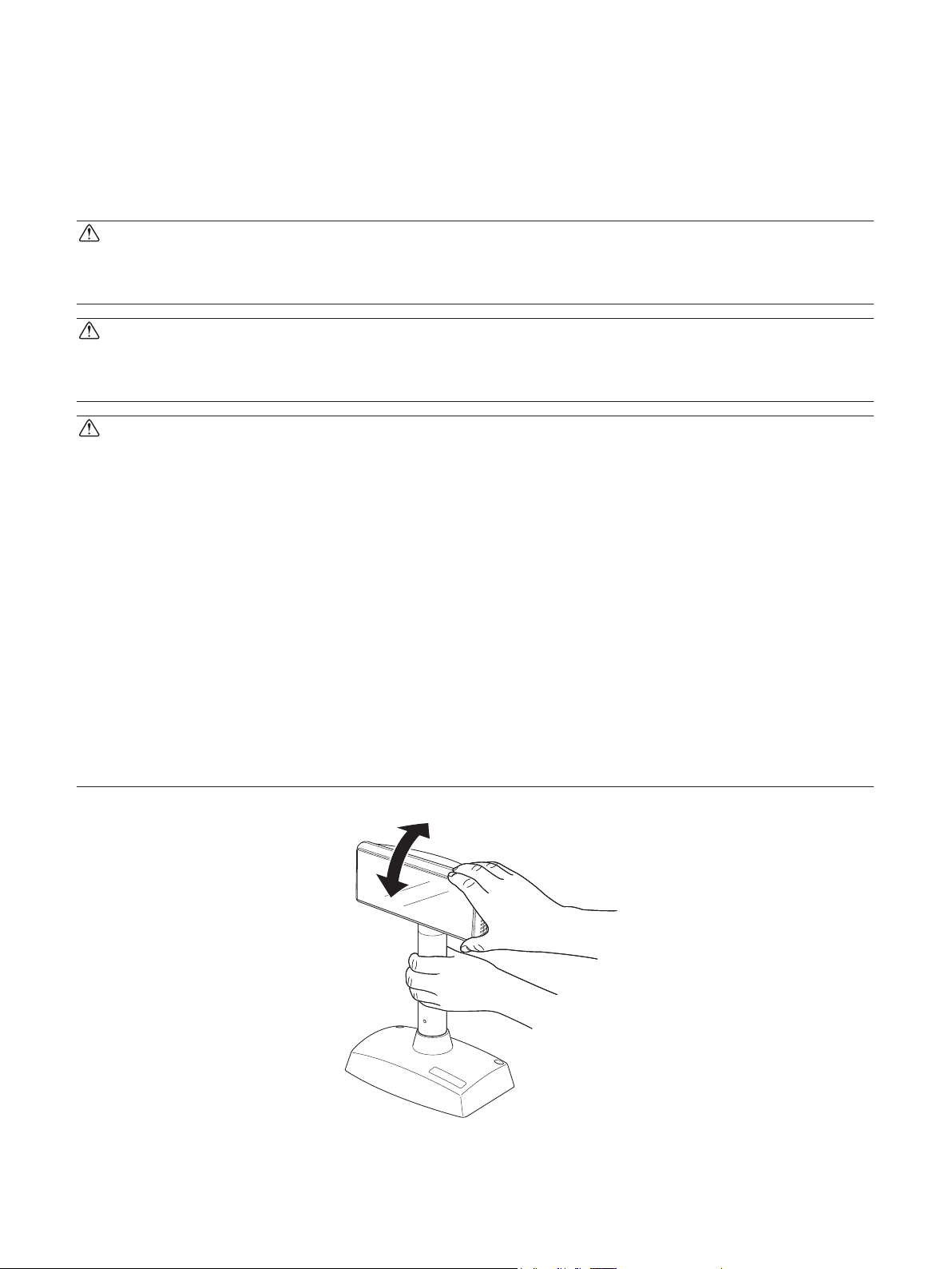
to re. To adjust the angle of the display unit, be sure to hold it by its support pillar.
3 Hold it by its support pillar to adjust the angle of the display unit.
– ii –
Page 4

CAUTION
3 Do not use in locations subject to high humidity or dust levels.
Excessive humidity and dust may cause equipment damage, re, or shock.
3 Do not place heavy objects on top of this product. Never stand or lean on this prod-
uct.
Equipment may fall or collapse, causing breakage and possible injury.
3 Do not plug in the cables differently from the instructions in the manual.
Wrong connection may cause equipment damage and re.
3 Hold the plug when pulling out the cable.
3 Do not use this product near the device generating electric noises.
3 Do not put heavy objects on the cable, and bend it heavily.
3 Do not come closer to the display.
3 Do not use this product in the dark.
– iii –
Page 5

TABLE OF CONTENTS
1. Unpacking .................................................................................................................................................1
1-1. Unpacking ....................................................................................................................................
2. Installation Examples ..............................................................................................................................2
2-1. Selecting a Base Stand .................................................................................................................
2-2. Combinations of Support Pillars ..................................................................................................
3. Setting Up .................................................................................................................................................3
3-1. Using the Surface-Mount Stand ...................................................................................................
3-2. Installing Support Pillars ..............................................................................................................
3-3. Using the Fixed-Mount Stand ......................................................................................................
3-4. Installing the Software .................................................................................................................
4. Setting the DIP Switch .............................................................................................................................8
5. Specifications ..........................................................................................................................................10
5-1. General Specifications ...............................................................................................................
6. Character Code List ..............................................................................................................................12
6-1. International Character Set List .................................................................................................
6-2. Character Code Table .................................................................................................................
10
12
12
1
2
2
3
4
6
7
Please access the following URL
http://www.star-m.jp/eng/dl/dl02.htm
for the latest revision of the manual.
Page 6
1. Unpacking
1-1. Unpacking
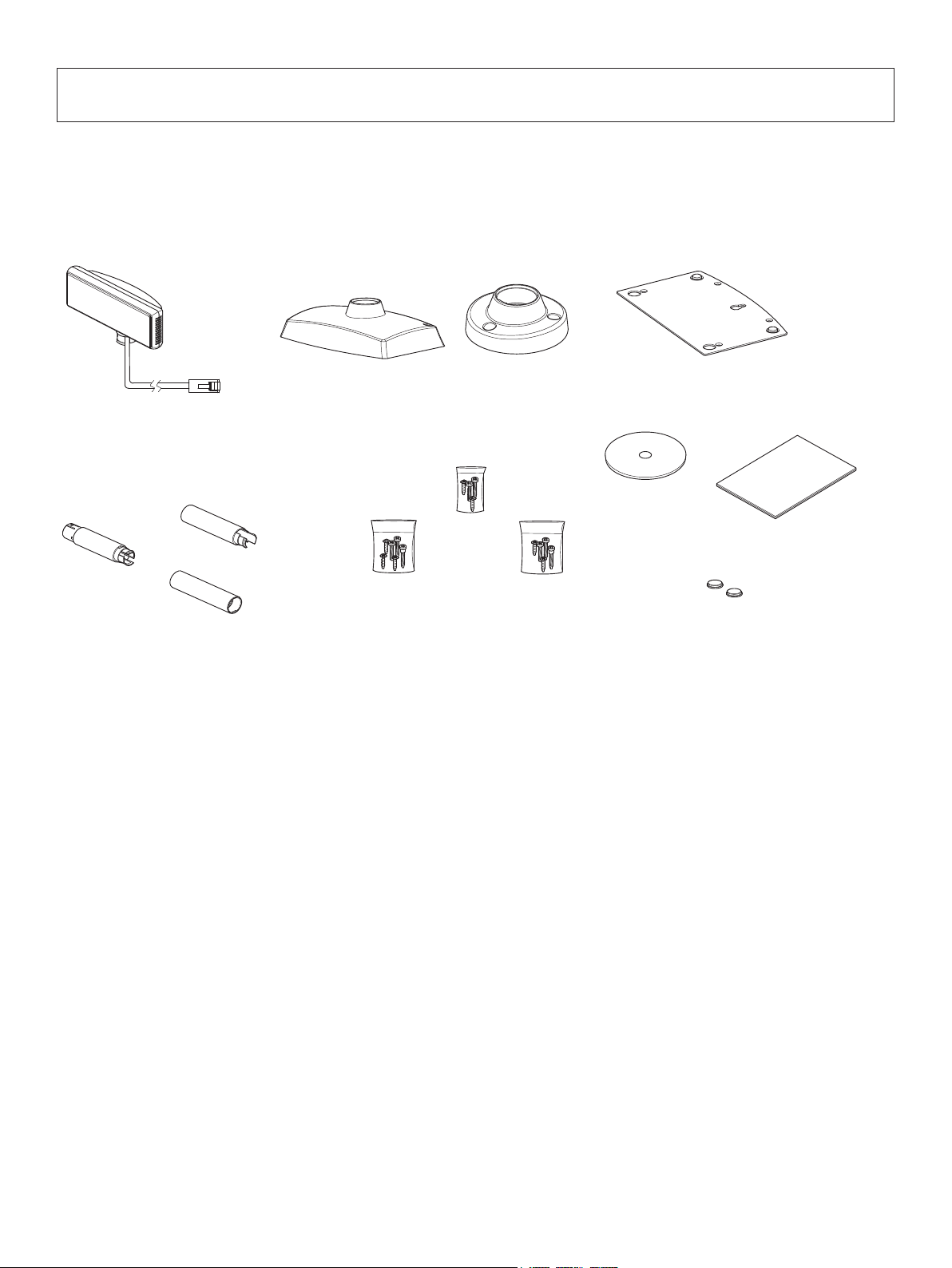
After unpacking the unit, check that all the necessary accessories are included in the package.
Display (1 unit)
Pillar A
Pillar B
Extension Support
(3 pieces)
Pillar C
Stand (2 items)
Screw (4 pieces)
Nut (3 pieces)
Washer (6 pieces)
Screw
(4 pieces)
( 1 piece )
Screw
(4 pieces)
Screw Bag
Stand Plate (2 units)
CD-ROM
Safty Instruction Sheet
( 1 piece )
Rubber Foot (2 pieces)
If anything is missing, contact the dealer where you bought the equipment and ask them to
supply the missing part. Note that it is a good idea to keep the original box and all the packing
materials just in case you need to pack the equipment up again and send it somewhere at a later
– 1 –
Page 7

2. Installation Examples
This customer display consists of three pieces: the display unit, support pillar, and base stand.
For the base stand, two choices are available: a surface-mount stand that can be moved freely,
and a xed-mount stand that is screwed onto a table or the like.
To bring the display unit to an appropriate viewing height, the supplied support pillars can be
combined to attain four different heights.
2-1. Selecting a Base Stand
Table
Surface-mount stand example Fixed-mount stand example
2-2. Combinations of Support Pillars
Surface-mount stand example
Fixed-mount stand example
– 2 –
Page 8

3. Setting Up
3-1. Using the Surface-Mount Stand
1) Route the USB interface cable through the surface-mount stand.
2) Insert the stem of the display unit into the surface-mount stand until it clicks into place.
3) Pull the USB interface cable out of the cutout in the surface-mount stand as shown below.
4) Attach the stand plate to the surface-mount position of the surface-mount stand, and tighten
it with four screws.
5) Connect the USB interface cable into the USB port of the host computer.
Note: The rubber feet come already afxed to the stand plate. In addition, two rubber feet
are supplied with the unit. They are spares to be used if the existing ones become
detached.
Screw
Stand plate
Surface-mount stand
Rubber foot
– 3 –
Page 9

3-2. Installing Support Pillars
To use only one of the support pillars, install support pillar C.
To use two of them, install support pillars B and C. To use three of them, install support pillars
A, B, and C.
Support pillar A Support pillar CSupport pillar B
Support pillar C
Support pillar C
Support pillar A Support pillar ASupport pillar B
Support pillar B
3-2-1. Using One Support Pillar
1) Route the USB interface cable through support pillar A, and insert the stem of the display
unit into support pillar A.
2) Insert support pillar A into the surface-mount stand until it clicks into place.
Support pillar A
– 4 –
Page 10

3-2-2. Using Two Support Pillars
1) Route the USB interface cable through support pillar C, and insert the stem of the display
unit into support pillar C.
2) Insert support pillar B into support pillar C until it clicks into place.
3) Insert support pillar B into the surface-mount stand until it clicks into place.
Support pillar BSupport pillar C
3-2-3. Using Three Support Pillars
1) Route the USB interface cable through support pillar C, and insert the stem of the display
unit into support pillar C.
2) Insert support pillar B into support pillar C until it clicks into place.
3) Insert support pillar C into support pillar A until it clicks into place.
4) Insert support pillar C into the surface-mount stand until it clicks into place.
Support pillar A
Support pillar BSupport pillar C
CAUTION
The USB interface cable has sufcient length to accommodate the maximum length of the support pillar with all the pieces connected. If fewer pieces are used for the support pillar, there
will be some slack in the cable. If you push the extra length of the cable into the support pillar
to take up the slack, make sure the cable moves freely.
As the display unit is turned, it pulls on the cable. Thus, if the display unit is turned while the
cable is tucked tightly into the support pillar, it can apply undue force on the connector and lead
to a contact failure. Therefore, do not tuck the cable tightly into the support pillar.
– 5 –
Page 11

3-3. Using the Fixed-Mount Stand
1) Route the USB interface cable through the xed-mount stand and pull it out of the cutout
in the xed-mount stand.
2) Insert the stem of the display unit into the xed-mount stand until it clicks into place.
3) Tighten the three screws to mount the xed-mount stand onto a table or the like.
4) Connect the USB interface cable into the USB port of the host computer.
To extend the length of the support pillar, refer to “3-2. Installing Support Pillars”.
Support pillar C
Support pillar B
Support pillar A
– 6 –
Page 12

3-4. Installing the Software
Here is the procedure for installing the driver and utility software, which are stored on the supplied CD-ROM.
The procedure applies to the Windows operating systems shown below.
• Windows 2000
• Windows XP
• Windows Vista 32-Bit
(1) Turn ON the power to your PC to start Windows.
(2) Insert the supplied CD-ROM (Drivers and Utilities) into the CD-ROM drive.
(3) Follow the instructions that appear on the screen.
Refer to the software manual in the Documents folder of the CD-ROM for more information.
For instructions on the Windows Vista 64-Bit, refer to the software manual location in the
“Documents” folder of the CD-ROM.
– 7 –
Page 13

4. Setting the DIP Switch
ON
1
2
3
4
5
6
7
8
9
10
OFF
A DIP switch located at the bottom of the display unit enables the various settings as shown in
the table on the next page. The settings may be changed as follows.
(1) Power OFF the host computer or disconnect the USB interface cable.
(2) Remove the cover from the DIP switch located at the bottom of the display unit.
(3) Use a pointed tool to change the settings of the DIP switch.
(4) Reinstall the cover on the DIP switch.
Note: The new setting takes effect when the host computer is powered ON or the USB
interface cable is reconnected.
CAUTION
Disconnect the USB interface cable before removing the cover from the DIP switch. If the cover
is removed while the host computer is running and the USB interface cable is connected, the
unit may become damaged due to a short circuit.
– 8 –
Page 14

DIP Switch
No. 1 2 3 4 5 6 7 8
9 10
OFF
ON
Functions of DIP Switch
DIP switch provides the following functions:
Switch Description ON OFF
1 Demo mode Active Inactive
2-5 International character set See below
6-8 Code page See below
9 Cursor Active Inactive
10 Emulation ESC/POS mode Star mode
The factory setting has switches 2,3,7, and 8 ON, and the remainder OFF.
■ International character set
Switch 5 Switch 4 Switch 3 Switch 2 Character set
OFF OFF OFF OFF USA
OFF OFF OFF ON France
OFF OFF ON OFF Germany
OFF OFF ON ON UK *
OFF ON OFF OFF Denmark I
OFF ON OFF ON Sweden
OFF ON ON OFF Italy
OFF ON ON ON Spain
ON OFF OFF OFF Japan
ON OFF OFF ON Norway
ON OFF ON OFF Denmark II
ON OFF ON ON Spain2
ON ON OFF OFF Latin America
ON ON OFF ON Korea
ON ON ON OFF Ireland
ON ON ON ON Legal
* Indicates factory setting
■ Code page
Switch 8 Switch 7 Switch 6 Code page Page No.
OFF OFF OFF
OFF OFF ON Katakana 1
OFF ON OFF PC860(Portuguese) 3
OFF ON ON PC863(Canadian-French) 4
ON OFF OFF PC865(Nordic) 5
ON OFF ON PC866(Cyrillic Russian) 17
ON ON OFF PC858(Europe) 19 *
ON ON ON Katakana 2 255
* Indicates factory setting
– 9 –
PC437(USA, Standard Europe)
0
Page 15

5. Specications
5-1. GeneralSpecications
(1) Display unit
Display type: vacuum uorescent display tube
Display characters: 40 characters (20 digits x 2 lines)
Display color: Blue green
Character composition: 5 x 7 dot matrix
Character size: 3.5 x 5.0 mm
Character type: 95 alphanumeric characters
Graphic characters: 128 characters
Supply voltage: 5V 500mA (supplied through USB port)
Power consumption: Approx. 2W (DC 5V 500mA)
(2) External dimensions
Display unit: Width 175mm x Depth 53 mm x Height 72 mm
Height
Using surface-mount stand: 142 mm, 272 mm., 387 mm, 517 mm
Using xed-mount stand: 124 mm, 254 mm, 369 mm, 499 mm
Base
Surface-mount stand: Width 175 mm x Depth 110 mm x Height 61 mm
Fixed-mount stand: ø80 x Height 40 mm
Tilt angle: 30°max.
Horizontal rotation angle: 300°max.
Weight: Approx. 840 g
(3) Interface
Interface: USB 2.0
(4) Reliability specication
MTBF (Mean Time Between Failures): 20,000 hours (vacuum uorescent display
tube only) half-life
(5) Operating environment
Temperature 5°C to 45°C
Humidity: 10% RH to 90% RH (no condensation)
(6) Storage environment
Temperature -20°C to 60°C
Humidity: 10% RH to 90% RH (no condensation)
– 10 –
Page 16

175mm
175mm
175mm
60mm
80mm
175mm
124mm
254mm
53.0mm
369mm
499mm
72mm
175mm
146mm
175mm
175mm
175mm
175mm
110mm
72mm
142mm
272mm
387mm
517mm
53mm
Surface-Mount Stand Type
Fixed-Mount Stand Type
– 11 –
Page 17

6. Character Code List
6-1. International Character Set List
6-2. Character Code Table
Note: Characters 20(H) to 7E(H) vary with the setting of the international character set.
• PC437 (USA,Standard Europe) : (00)H • Katakana : (01)H
– 12 –
Page 18

• PC860 (Portuguese) : (03)H • PC863 (Canadian-French) : (04)H
• PC865 (Nordic) : (05)H • PC866 (CyrillicRussian) : (011)H
• PC858 (Europe) : (13)H • Katakana 2 : (FF)H
– 13 –
Page 19

OVERSEAS SUBSIDIARY COMPANIES
STAR MICRONICS AMERICA, INC.
1150 King Georges Post Road, Edison, NJ 08837-3729 U.S.A.
Tel: (int+1)-732-623-5555, Fax: (int+1)-732-623-5590
ELECTRONIC PRODUCTS DIVISION
STAR MICRONICS CO., LTD.
536 Nanatsushinya, Shimizu-ku, Shizuoka,
424-0066 Japan
Tel: (int+81)-54-347-0112, Fax: (int+81)-54-347-0709
Please access the following URL
http://www.star-m.jp/eng/dl/dl02.htm
for the latest revision of the manual.
STAR MICRONICS EUROPE LTD.
Star House, Peregrine Business Park, Gomm Road,
High Wycombe, Bucks, HP13 7DL, U.K.
Tel: (int+44)-1494-471111, Fax: (int+44)-1494-473333
STAR MICRONICS ASIA LTD.
Rm. 1901-5, 19/F., Enterprise Square Two,
3 Sheung Yuet Road, Kowloon Bay, Hong Kong
Tel: (int+852)-2796-2727, Fax: (int+852)-2799-9344
SCD122U HM2.0 2008.05.30
80875051CD
 Loading...