

Page 1

STRIP HEATERS
IL2532
MODEL
SC18, SC24, SC30, SC36,
SC42, SC48, SC60, SC72
Installation and
Operation
Instructions
2M-Z16424 Rev. - 10/31/2012
1
SC36P
Page 2

2
These symbols are intended to alert the user to the presence of
important operating and maintenance instructions in the manual
accompanying the appliance.
RETAIN THIS MANUAL FOR FUTURE REFERENCE
NOTICE
Using any part other than genuine Star factory supplied parts relieves the
manufacturer of all liability.
Star reserves the right to change specications and product design without
notice. Such revisions do not entitle the buyer to corresponding changes,
improvements, additions or replacements for previously purchased
equipment.
Due to periodic changes in designs, methods, procedures, policies and
regulations, the specications contained in this sheet are subject to change
without notice. While Star International Holdings Inc., Company exercises
good faith efforts to provide information that is accurate, we are not
responsible for errors or omissions in information provided or conclusions
reached as a result of using the specications. By using the information
provided, the user assumes all risks in connection with such use.
MAINTENANCE AND REPAIRS
Contact your local authorized service agent for service or required maintenance.
Please record the model number, serial number, voltage and purchase date in the area below and have it ready when
you call to ensure a faster service.
SAFETY SYMBOL
Model No.
Serial No.
Voltage
Purchase Date
Business 8:00 am to 4:30 p.m. Central Standard Time
Hours:
Telephone: (314) 678-6303
Fax: (314) 781-2714
E-mail [email protected]
Website: www.star-mfg.com
Service Help Desk
Authorized Service Agent Listing
Reference the listing provided with the unit
or
for an updated listing go to:
Mailing Address: Star International Holdings Inc., Company
10 Sunnen Drive
St. Louis, MO 63143
U.S.A
2
Page 3
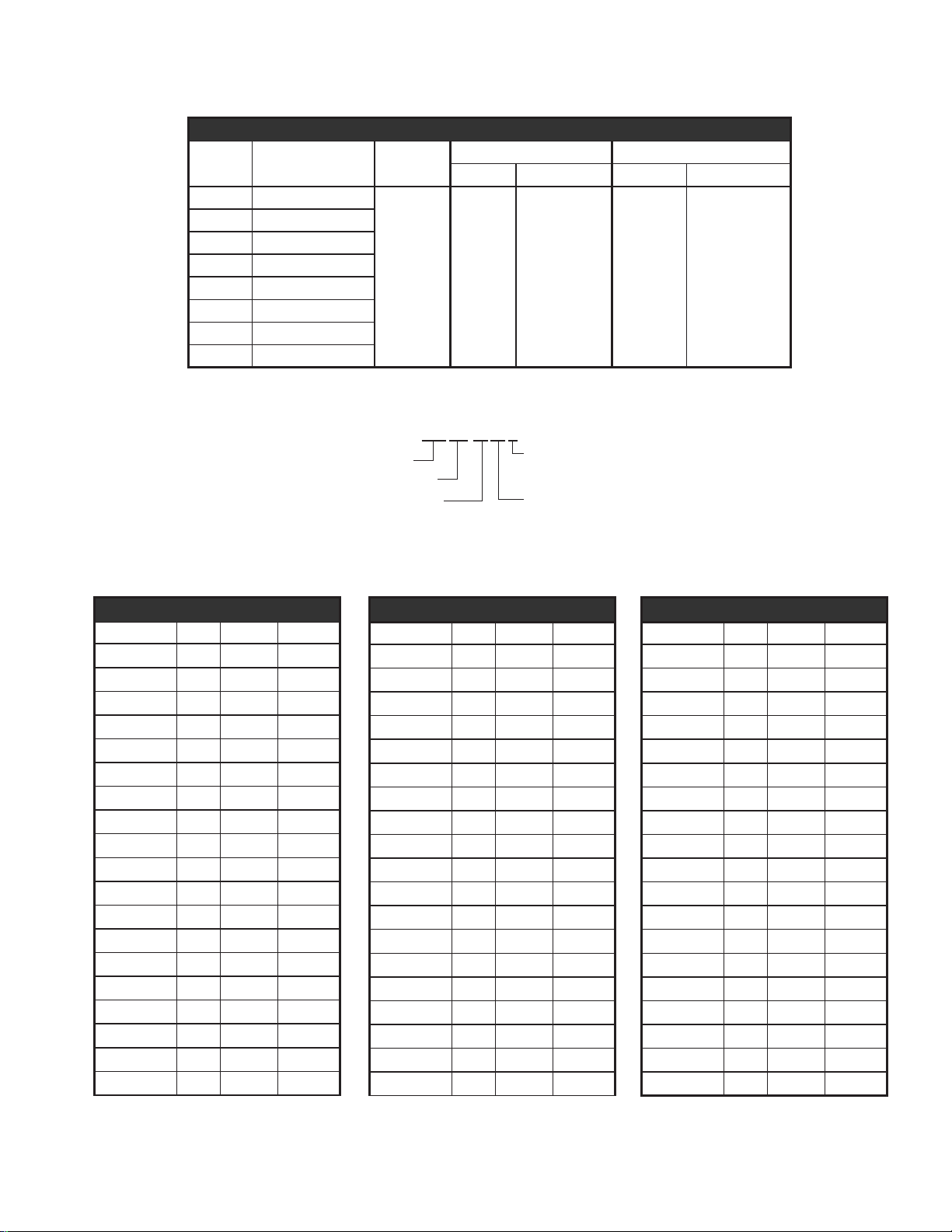
SC24MLIP
None: Low Watt
M: Medium Watt
H: High Watt
I: Infinite
no / I: Toggle
L: Lights
A: Attached Control Box
R: Remote Control Box
P: Plug
no / P: Conduit
SC: Model Designation
Length
Model Length Height
SC18 18” (45.7 cm)
SC24 24” (61.0 cm)
SC30 30” (76.2 cm)
SC36 36” (91.4 cm)
SC42 42” (106.7 cm)
SC48 48” (121.9 cm)
SC60 60” (152.4 cm)
SC72 72” (182.9 cm)
2.5”
(5.1 cm)
Dimensions
Single Model Dual Model
Width Width w Lights Width Width w Lights
6”
(15.25 cm)
9”
(22.9 cm)
15”
(38.1 cm)
(45.7 cm)
18”
Electrical Specications
MODEL NO. VOLTS WATTS AMPS.
SC18HP 120 375 3.1
SC18H 120 375 3.1
SC24P 120 375 3.1
SC24 120 375 3.1
SC24HP 120 525 4.4
SC24H 120 525 4.4
SC24HI 120 525 4.4
SC24HL 120 645 5.4
2M-Z16424; Strip-Heater
SC24DH 120 1050 8.8
SC24DHL 120 1170 9.8
SC24MIP 120 675 5.6
SC24MR 120 675 5.6
SC24H 208 525 2.5
SC24MR 208 675 3.2
SC30 120 475 4.0
SC30HP 120 685 5.7
SC30H 120 685 5.7
SC36P 120 600 5.0
SC36 120 600 5.0
Electrical Specications
MODEL NO. VOLTS WATTS AMPS.
SC36HP 120 825 6.9
SC36H 120 825 6.9
SC36HI 120 825 6.9
SC36HL 120 1005 8.4
SC36DH 120 1650 13.8
SC36DHL 120 1830 15.3
SC36MIP 120 1025 8.5
SC36MR 120 1025 8.5
SC36H 208 825 4.0
SC36MR 208 1025 4.9
SC42HP 120 925 7.7
SC42H 120 925 7.7
SC48P 120 825 6.9
SC48 120 825 6.9
SC48HP 120 1125 9.4
SC48H 120 1125 9.4
SC48HI 120 1125 9.4
SC48HL 120 1105 9.2
SC48DH 120 1850 15.4
3
Electrical Specications
MODEL NO. VOLTS WATTS AMPS.
SC48DHL 120 2490 20.8
SC48MIP 120 1325 11.0
SC48MR 120 1325 11.0
SC48H 208 1125 5.4
SC48MR 208 1325 6.4
SC60P 120 1075 9.0
SC60 120 1075 9.0
SC60HP 120 1425 11.9
SC60H 120 1425 11.9
SC60HI 120 1425 11.9
SC60MIP 120 1725 14.4
SC60MR 120 1725 14.4
SC60H 208 1425 6.9
SC60MR 208 1725 8.3
SC72HP 120 1750 14.6
SC72H 120 1750 14.6
SC72MR 120 2100 17.5
SC72H 208 1750 8.4
SC72MR 208 2100 10.1
Page 4
GENERAL INFORMATION
This equipment is designed and sold for commercial use only by personnel trained and
experienced in its operation and is not sold for consumer use in and around the home nor for
use directly by the general public in food service locations.
Before using your new equipment, read and understand all the instructions & labels
associated with the unit prior to putting it into operation. Make sure all people associated with
its use understand the units operation & safety before they use the unit.
All shipping containers should be checked for freight damage both visible and concealed.
This unit has been tested and carefully packaged to insure delivery of your unit in perfect
condition. If equipment is received in damaged condition, either apparent or concealed, a
claim must be made with the delivering carrier.
Concealed damage or loss - if damage or loss is not apparent until after equipment is
unpacked, a request for inspection of concealed damage must be made with carrier within
15 days. Be certain to retain all contents plus external and internal packaging materials for
inspection. The carrier will make an inspection and will supply necessary claim forms.
UNCRATING AND INSPECTING
Unpack the unit and components from the shipping container.
Remove all visible packing material and those from inside the
cooking chamber. If damage is discovered, le a claim immediately
with the carrier that handled the shipment. Do not operate the unit if
it was damaged during shipping.
WARNING
ELECTRICAL INSTALLATION
The strip heater is equipped for the voltage indicated on the nameplate. It will operate on
alternating current (AC) only.
DO NOT CONNECT TO DIRECT CURRENT (DC).
The installation of the electric griddle should conform to the:
NATIONAL ELECTRIC CODE AND ALL LOCAL ELECTRIC CODES AND ORDINANCES AND
THE LOCAL ELECTRIC COMPANY RULES AND REGULATIONS
2M-Z16424; Strip-Heater
For your protection we recommend that a qualied electrician install the strip heater. He
should be familiar with electrical installations and all electric codes. Proper connections and
power supply are essential for efcient performance. The supply circuit should be properly
fused and equipped with a means of disconnecting, as required by local electrical code.
1. Refer to the product nameplate. Verify the electrical service power. Voltage and phase must
match the nameplate specications. Wiring the warmer to the wrong voltage can severely
damage the unit or cause noticeably decreased performance.
2. Available electrical service amperage must meet or exceed the specications listed on the
specication sheet provided with the warmer.
3. This unit must be connected to an appropriate building ground.
NOTE: Wire gauge, insulation type and temperature rating , as well as type, size and
construction of conduit, must meet or exceed applicable specications of local codes and of
the National Electrical Code.
4
Page 5
ELECTRICAL INSTALLATION continued
Conduit Connection
Units supplied with conduit connections have had
all internal connections pre-wired and must be
installed using angle brackets. All nal electrical
connections MUST be performed by a licensed
electrician familiar with all local codes and
ordinances.
Units containing a conduit connection MUST have
a permanent mounting.
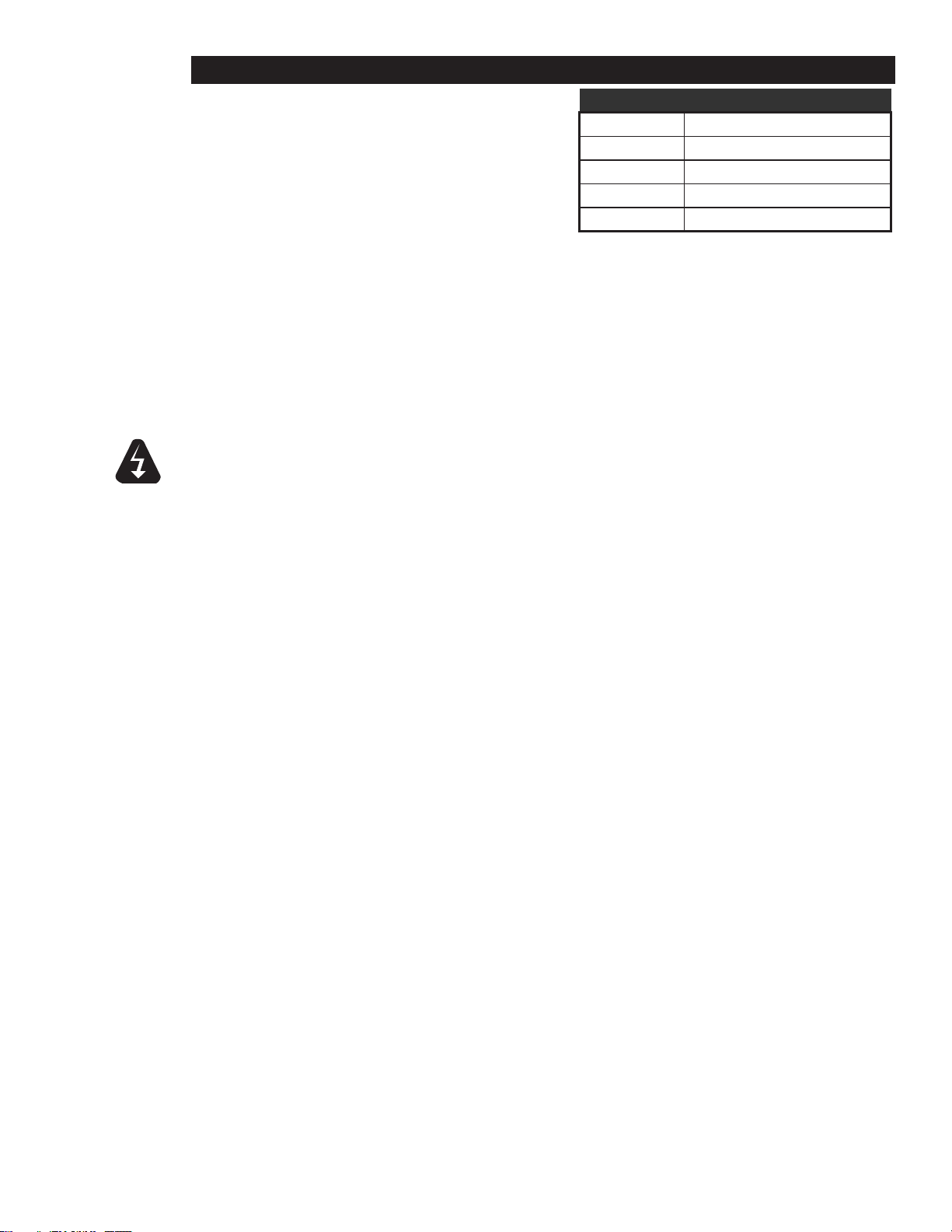
Circuits Minimum AWG Copper wire needed
up to 15 amps No. 14
15 to 20 amps No. 12
20 to 25 amps No. 10
25 to 30 amps No. 8
Supply Wire
Power Cord
120V Units provided with a power cord have been installed at the factory. These units can
use either the portable leg assemblies or a permanent mount. If a permanent mount is used
a 3" gap must be maintained from all adjacent surfaces.
Units with portable leg assemblies must have a power cord.
DO NOT CUT OR REMOVE THIS PLUG OR GROUNDING PRONG FROM THE PLUG.
WARNING
2M-Z16424; Strip-Heater
CONNECT/PLUG UNIT INTO DEDICATED A.C LINE ONLY SPECIFIED ON THE DATA PLATE
OF THE UNIT.
5
Page 6
IL2536
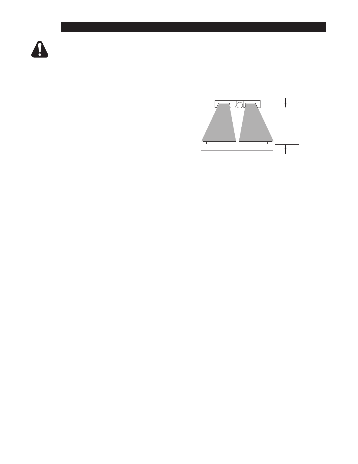
Low Wattage: 8” - 11”
(20 - 28cm)
(28 - 35cm)
(35 - 45cm)
Medium Wattage: 11” - 14”
High Wattage: 14” - 18”
CAUTION
INSTALLATION
TO REDUCE THE RISK OF FIRE, THE APPLIANCE IS TO BE INSTALLED IN NONCOMBUSTIBLE SURROUNDINGS ONLY, WITH NO COMBUSTIBLE MATERIAL WITHIN 18"
(45.7 cm) OF THE SIDES, FRONT OR REAR OF THE APPLIANCE OR WITHIN 40"
(101.6 cm) ABOVE THE APPLIANCE. THE APPLIANCE IS TO BE MOUNTED ABOVE
SURFACES OF NON-COMBUSTIBLE CONSTRUCTION WITH NON-COMBUSTIBLE
SURFACES AND SURFACE FINISH, WITH NO COMBUSTIBLE MATERIAL AGAINST THE
UNDERSIDE.
Adjustable Angle Bracket Mounting
Mounting a strip heater with angle brackets
permanently attaches the unit to the
underside of a non-combustible surface.
Units can be mounted to the underside
of a at shelf or one with a rolled/anged
edges. Adjustable angle brackets provide
the necessary gap between the unit and a
combustible surface.
Single, portable units can be mounted to a combustible surface as long as a 3"
Note:
clearance is maintained between the top of the unit and the combustible surface.
IMPORTANT
Before installation refer to the recommended clearance requirements for your specic
unit.
Flanged Shelf Mounting
In situations where the mounting surface has a anged edge, it is important that the minimum
clearance is calculated from the top of the unit to that anged edge, and not the mounting
surface. This prevents an excess of excessive heat build-up.
Installing Angle Brackets:
1. Place unit on a surface with element side down.
2. Remove the 4 screws on each side.
3. Place the adjustable angle bracket in position and re-install the screws, repeat on opposite end.
Note: make certain you maintain the required minimum clearance.
4. Place the unit into position and adhere using appropriate hardware (not included).
2M-Z16424; Strip-Heater
6
Page 7
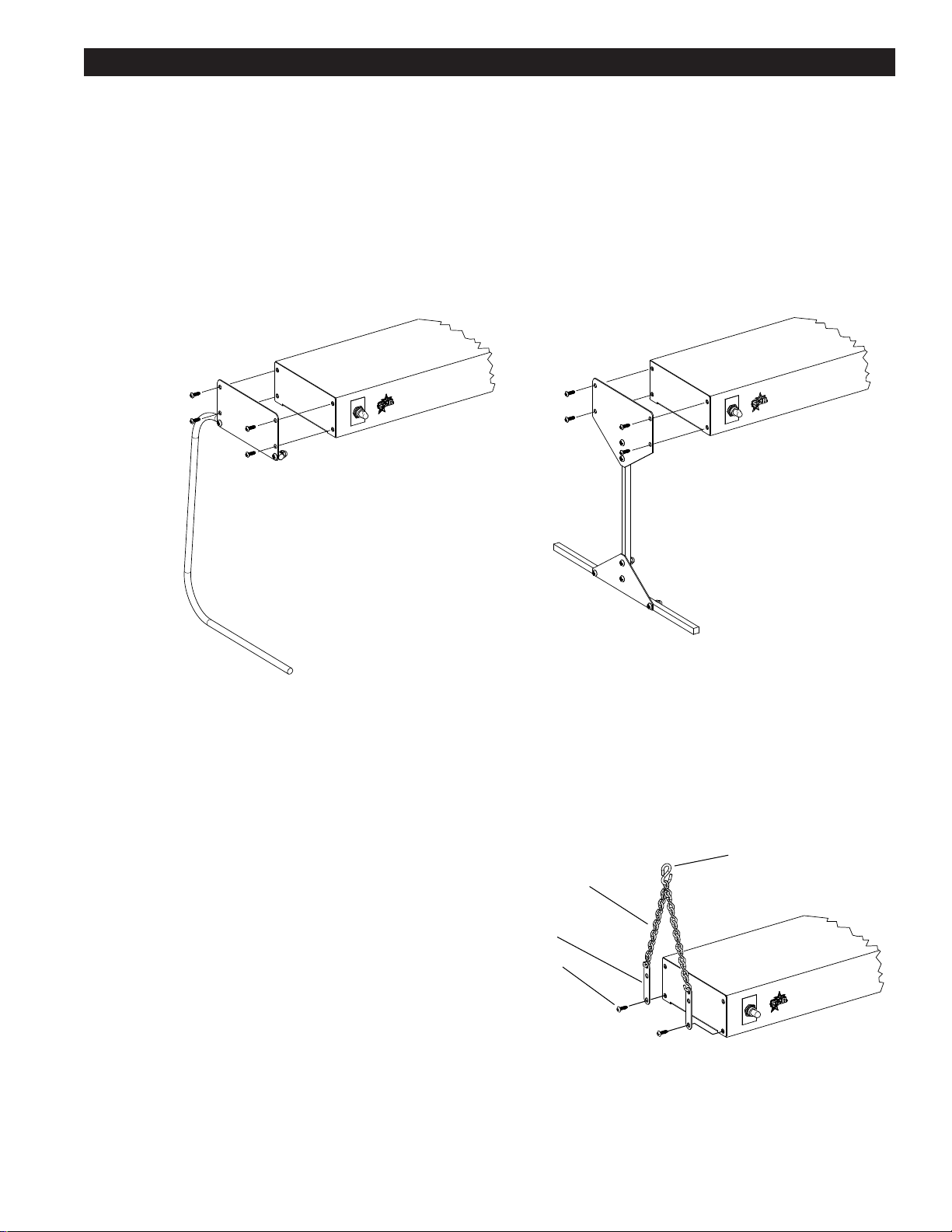
INSTALLATION continued
C-Leg Portable Stand T-Leg Portable Stand
IL2534
Chain Suspension System
“S” Hook
6” Connecting
Chain
Tab
IL2535
Screw
Installing Portable Legs
Single strip heaters containing a power cord can have portable leg assemblies like the C-Leg & T-Leg
Stands shown here.
DO NOT PLACE ANYTHING ON TOP OF THE STRIP HEATERS, THE SURFACE GETS HOT.
1. Position the unit upside down, it must be unplugged.
2. Remove the 4 screws on each side.
3. Line up the Portable stand (C or T) and secure with hardware previously removed.
Install the same to both sides.
4. Turn unit over and place into position.
Installing Chain Suspended Units
Single, 120V units containing a power cord can be mounted using a chain suspension assembly as shown
here.
2M-Z16424; Strip-Heater
1. Overhead surface should be sturdy enough to
withstand the weight of the unit.
2. Prepare the overhead mountings to receive the "S"
hook so the distance between them match the width of
the unit.
3. Remove the two top screws on each side of the unit
as shown here.
4. Using the screws just removed, install the tabs, one
on each corner.
5. Hook one end of each of the 6" Connecting Chain
assemblies to each tab just installed.
6. Hook the other ends of the 6" Connecting Chain
7
Page 8
CAUTION
OPERATION
INITIAL START-UP
Before using the unit for the rst time, wipe down the surface a damp cloth with some mild
detergent. Let the unit heat up without product for approximately 30 minutes. The unit may
emit a certain amount of smoke as the surfaces reaches its operating temperature. Do not
be alarmed, as the smoke is caused by oils associated with the manufacturing process and
will stop when the burn off is complete. Wipe surface clean when complete.
OPERATION
Controls
Toggle Switch; Turns "ON/OFF" the heating element, on 120V turns lights "ON/OFF"
Light Switch: Turns "ON/OFF" lights (208/240V only)
Innite Switch: Allows you to set the element to a setting that works best for you.
(120V units only)
CERTAIN SURFACES ARE EXTREMELY HOT DURING OPERATION AND CARE SHOULD BE
TAKEN WHILE USING THIS UNIT.
CLEANING
To keep your strip heater looking new and operating properly follow the following steps on a
daily basis.
1. Turn the power off to all heating elements and allow unit to cool.
2. Once cooled, remove the Pan Rail and wash with warm water and mild detergent.
3. Wipe exterior surface of unit using a soft damp cloth, warm water and mild detergent.
4. Stubborn stains can be removed using a non-abrasive cleaner.
CAUTION
DO NOT IMMERSE UNIT IN WATER OR HOSE DOWN WITH WATER TO CLEAN. USE
A DAMP SOFT CLOTH WITH A VERY MILD SOAP TO WIPE DOWN OUTSIDE OF THE
WARMER.
MAINTENANCE
LIGHT BULB REPLACEMENT
To replace the bulb, remove the element guard by removing screws, (NOTE: element guard
is extremely hot and should be allowed to cool) set the screws and guard aside. With
unit cool, remove the bad bulb and replace with a NSF standard bulb made for food holding
and display area, for replacement bulb contact a qualied Star service agent of call Star parts
department at 314-678-6303.
2M-Z16424; Strip-Heater
8
Page 9

2M-4497-2 6/1312
The foregoing warranty is in lieu of any and all other warranties expressed or implied and constitutes the entire warranty.
FOR ASSISTANCE
Should you need any assistance regarding the Operation or Maintenance of any Star equipment; write, phone, fax or email our Service Department.
In all correspondence mention the Model number and the Serial number of your unit, and the voltage or type of gas you are using.
ALL:
* Pop-Up Toasters
* Butter Dispensers
* Pretzel Merchandisers
(Model 16PD-A Only)
* Pastry Display Cabinets
* Nacho Chip Merchandisers
* Accessories of any kind
* Sneeze Guards
* Pizza Ovens
(Model PO12 Only)
* Heat Lamps
* Pumps-Manual
Visit our Website at: www.star-mfg.com Email: [email protected]
THOROUGHLY INSPECT YOUR UNIT ON ARRIVAL
This unit has been tested for proper operation before leaving our plant to insure delivery of your unit in perfect condition. However, there are instances in which
the unit may be damaged in transit. In the event you discover any type of damage to your product upon receipt, you must immediately contact the transportation
company who delivered the item to you and initiate your claim with same. If this procedure is not followed, it may affect the warranty status of the unit.
LIMITED EQUIPMENT WARRANTY
All workmanship and material in Star products have a one (1) year limited warranty on parts & labor in the United States and Canada. Such warranty is limited
to the original purchaser only and shall be effective from the date the equipment is placed in service. Star's obligation under this warranty is limited to the repair
of defects without charge, by the factory authorized service agency or one of its sub-agencies. Models that are considered portable (see below) should be taken
to the closest Star service agency, transportation prepaid.
> Star will not assume any responsibility for loss of revenue.
> On all shipments outside the United States and Canada, see International Warranty.
* The warranty period for the Ultra-Max, Hot Plates, Griddles, Charbroilers is (3) years parts & labor.
* The warranty period for the Star-Max, Charbroilers, Griddles, Hot Plates, Fryers & Finishing Oven is (2) years parts & labor.
* The warranty period for the JetStar six (6) ounce & Super JetStar eight (8) ounce series popcorn machines is two (2) years.
* The warranty period for the Chrome-Max Griddles is ve (5) years on the griddle surface. See detailed warranty provided with unit.
* The warranty period for Teon/Dura-Tec coatings is one year under normal use and reasonable care. This warranty does not apply if damage occurs to
Teon/Dura-Tec coatings from improper cleaning, maintenance, use of metallic utensils, or abrasive cleaners, abrasive pads, product identiers and
point-of-sale attachments, or any other non-food object tha comes in continuous contact with the roller coating. This warranty does not apply to the
“non-stick” properties of such materials.
> This warranty does not apply to "Special Products" but to regular catalog items only. Star's warranty on "Special Products" is six (6) months on parts
and ninety (90) days on labor.
> This warranty does not apply to any item that is disassembled or tampered with for any purpose other than repair by a Star Authorized Service Center or
the Service Center's sub-agency.
> This warranty does not apply if damage occurs from improper installation, misuse, wrong voltage, wrong gas or operated contrary to the Installation and
Operating instructions.
> This warranty is not valid on Conveyor Ovens unless a "start-up/check-out" has been performed by a Factory Authorized Technician.
PARTS WARRANTY
Parts that are sold to repair out of warranty equipment are warranted for ninety (90) days. The part only is warranted, the labor to replace the part is NOT warranted.
SERVICES NOT COVERED BY WARRANTY
PORTABLE EQUIPMENT
Star will not honor service bills that include travel time and mileage charges for servicing any products considered "Portable" including items listed below.
These products should be taken to the Service Agency for repair:
1. Travel time and mileage rendered beyond the 50 mile radius limit
2. Mileage and travel time on portable equipment (see below)
3. Labor to replace such items that can be replaced easily during a daily cleaning
routine, ie; removable kettles on fryers, knobs, grease drawers on griddles, etc.
4. Installation of equipment
5. Damages due to improper installation
6. Damages from abuse or misuse
7. Operated contrary to the Operating and Installation Instructions
8. Cleaning of equipment
9. Seasoning of griddle plates
10. Voltage conversions
11. Gas conversions
12. Pilot light adjustment
13. Miscellaneous adjustments
14. Thermostat calibration and by-pass adjustment
15. Resetting of circuit breakers or safety controls or reset buttons
16. Replacement of bulbs
17. Replacement of fuses
18. Repair of damage created during transit, delivery, &
installation OR created by acts of God
* The Model 510FD, 510FF Fryer.
* The Model 526TOA Toaster Oven.
* The Model J4R, 4 oz. Popcorn Machine.
* The Model 518CMA & 526CMA Cheese Melter.
* The Model 12MC & 15MC & 18MCP Hot Food Merchandisers.
* The Model 12NCPW & 15NCPW Nacho Chip/Popcorn Warmer.
* All Hot Dog Equipment except Roller Grills & Drawer Bun Warmers.
* All Nacho Cheese Warmers except Model 11WLA Series Nacho Cheese Warmer.
* All Condiment Dispensers except the Model HPD & SPD Series Dispenser.
* All Specialty Food Warmers except Model 130R, 11RW Series, and 11WSA Series.
* All QCS/RCS Series Toasters except Model QCS3 & RCS3 Series.
* All Fast Steamer Models except Direct Connect Series.
2M-Z16424; Strip-Heater
9
Page 10
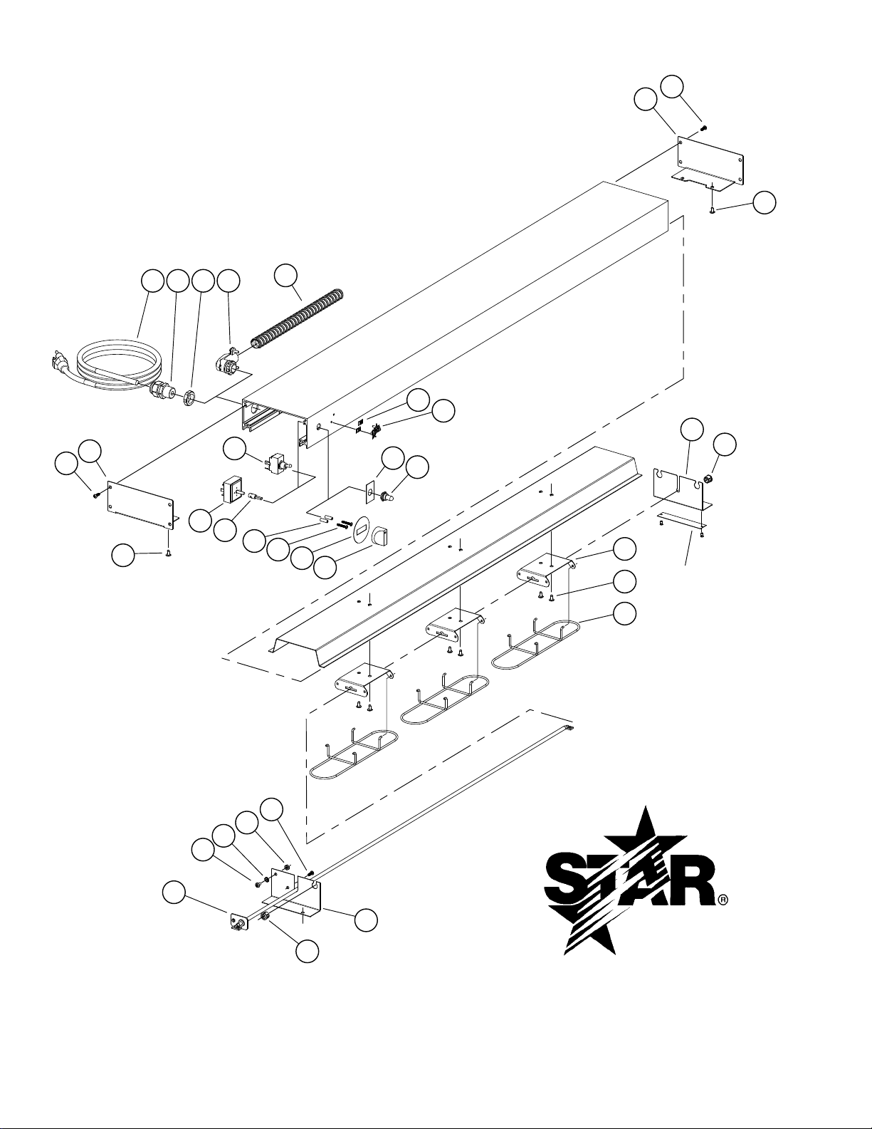
SK2619 Rev. - 9/7/2012
Model: Strip Heaters w/o Lights
1
2
3
31
1
6
3
9
10
11
4
5
18
19
20
16
17
21
17
22
24
25
26
21
Nameplate
7
8
12
13
14
2
30
2928
27
2M-Z16424; Strip-Heater
10
Page 11
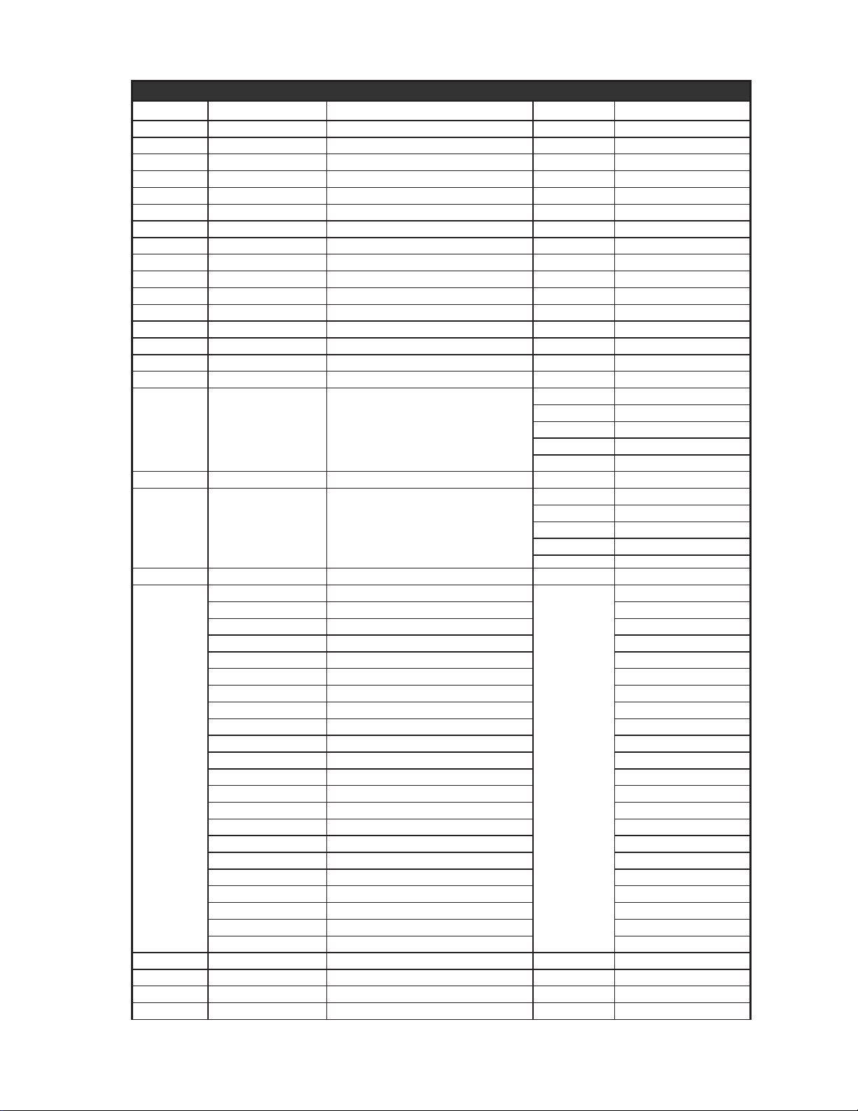
Parts List October 31, 2012
Model: SC18, SC24, SC30, SC36, SC42, SC48, SC60, SC72 Strip Heaters (non-lighted)
Fig No Part Number Description Quantity Application
1 D5-Z15915 COVER, END, 6 WIDE 2
2 2C-Z15735 SCR.8-32X1/2 F RHP STL NP 8
3 2C-6349 SCREW #8X3/8 B THP STL NP 4
4 2C-8477 CLIP .125 PO STL PHOS 2
5 2M-Z15305 STAR LOGO, SMALL 1
6 2E-Z16266 SWITCH,TOGGLE,DPST,150C 1
7 2M-12-07-0038 LABEL ON & OFF 1
8 2I-05-07-0013 BOOT SWITCH 1
9 2J-Z14323 INFINITE CONTROL-120V 1
10 2V-Z16288 EXTENSION, SHAFT 1
11 2C-Z15947 SPACER, INFINITE CONTROL 2
12 2C-Z16287 SCR. 4MMX0.7X25MM RHP SS 2
13 2M-Z16531 LABEL,-DIAL 1
14 2R-Z14443 KNOB-1.56” DIA X 1” 1
16 D5-Z15917 PNL,EL MT,NON-BKHD,6 IN. 1
17 2K-Z2895 BUSHING HEYCO OCB-500 2
1 SC18, SC24
2 SC30, SC36
18 D5-Z16035 BRACKET, ELEMENT, COMMON
19 2C-6349 SCREW #8X3/8 B THP STL NP 2 per bracket
20 2B-Z15628 ELEMENT GUARD,HEAT STRIP
21 D5-Z15916 PNL,EL MT,BULKHD SD,6 IN. 1
2N-Z15554-24 EL.,STD,24”,120V,375W
2N-Z15554-30 EL.,STD,30”,120V,475W SC30
2N-Z15554-36 EL.,STD,36”,120V,600W SC36
2N-Z15554-48 EL.,STD,48”,120V,825W SC48
2N-Z15554-60 EL.,STD,60”,120V,1075W SC60
2N-Z15558-18 EL.,MED, 18”,120V,375W SC18M
2N-Z15558-24 EL.,MED,24”,120V,525W SC24M
2N-Z15558-30 EL.,MED,30”,120V, 685W SC30M
2N-Z15558-36 EL.,MED,36”,120V, 825W SC36M
2N-Z15558-42
22
23 2C-Z15735 SCR.8-32X1/2 F RHP STL NP 1
24 2C-200014 SCREW 8-32X3/8 THP SS 1
25 2C-200176 WASHER #8 EXT SS 1
26 2C-Z6758 NUT 8-32 HEX SS 1
2N-Z15558-48 EL.,MED,48”,120V, 1125W SC48M
2N-Z15558-60 EL.,MED,60”,120V, 1425W SC60M
2N-Z15558-72 EL.,HIGH,72”,120V,1750W SC72M
2N-Z15559-24 EL,HIGH, 24” 120V, 675W SC24H
2N-Z15559-36 EL.,HIGH,36”,120V, 1025W SC36H
2N-Z15559-48 EL.,HIGH,48”,120V, 1325W SC48H
2N-Z15559-60 EL.,HIGH,60”,120V, 1725W SC60H
2N-Z15561-24 EL.,MED,24”,208V, 525W SC24M-208V
2N-Z15561-36 EL.,MED,36”,208V, 825W SC36M-208V
2N-Z15561-48 EL.,MED,48”,208V, 1125W SC48M-208V
2N-Z15561-60 EL.,MED,60”,208V,1425W SC60M-208V
2N-Z15561-72 EL.,MED,72”,208V,1750W SC72M-208V
EL.,MED,42”,120V, 925W SC42M
3 SC42, SC48
4 SC60
5 SC72
1 SC18, SC24
2 SC30, SC36
3 SC42, SC48
4 SC60
5 SC72
SC24
1
Page 12
Model: SC18, SC24, SC30, SC36, SC42, SC48, SC60, SC72 Strip Heaters (non-lighted)
Fig No Part Number Description Quantity Application
27 2E-6272 CORD SET 14-3 SJTO 6-8 1
28 2K-Z15730 CORDGRIP, LIQUID TIGHT, NYLON 1
29 2C-Z15731 LOCKNUT, NYLON 1
30 2K-34136X FTG FLEX CON 90 X 1/2 MOD 1
31 2E-Z15932 FLEX. CONDUIT,1/2 X 36 LG 1
D5-Z15790-24 INSULATION,6” WIDE, 24”
D5-Z15790-30 INSULATION,6” WIDE, 30” SC30
D5-Z15790-18 INSULATION,6” WIDE, 18” SC18
NI
D5-Z15790-36 INSULATION,6” WIDE, 36” SC36
D5-Z15790-48 INSULATION,6” WIDE, 48” SC48
D5-Z15790-60 INSULATION,6” WIDE, 60” SC60
D5-Z15790-72 INSULATION,6” WIDE, 72” SC72
1
SC24
12
 Loading...