

Star S714 Owner’s Manual

OPERATOR'S MANUAL
HOLMAN CONVEYOR TOASTERS
MODELS T710(H, TW, TX) T714(H, TW, TX) S710(H) S714(H) B710H
FOR SERVICE INFORMATION
U.S. AND CANADA CALL: 1-800-807-9054
24 HOURS/DAY 7 DAYS/WEEK
TABLE OF CONTENTS
UNCRATING AND INSPECTION PAGE 1
ASSEMBLY AND INSTALLATION PAGE 1
POWER SAVER SWITCH PAGE 2
SECURITY FEATURES PAGE 2A
COOKING PROCEDURES PAGE 3, 4
CLEANING PROCEDURES PAGE 4
TROUBLESHOOTING GUIDE PAGE 5, 6
MAINTENANCE PROCEDURES PAGE 7, 8, 9
PARTS LIST/EXPLODED VIEW PAGE 10, 11, 12, 13
DRAWINGS
CRUMB TRAY PAGE 1
LOAD AND UNLOAD TRAYS PAGE 1
ADJ. HEAT SHIELD, FRONT VIEW PAGE 3
COMPONENT ARRANGEMENT PAGE 6
HEATER TUBE INSTALLATION PAGE 7
DRIVE SYSTEM PAGE 9
WIRING DIAGRAMS [T710(H,TW)] PAGE 15, 16
WIRING DIAGRAMS [T714(H,TW)] PAGE 16, 17
WIRING DIAGRAMS [B710(H)] PAGE 18
WIRING DIAGRAMS [S710(H), Jamba Juice] PAGE 19
WIRING DIAGRAMS [S714(H)] PAGE 20
2M-HG0102
REV. 9/10/2008
OPERATOR'S MANUAL
HOLMAN CONVEYOR TOASTERS
UNCRATING AND INSPECTION
MODELS T710(H, TW, TX) T714(H, TW, TX) S710(H) S714(H) B710H
Unpack unit and components from container. Remove all visible packing
material, inspect unit for damage. If damage is discovered, file a claim
ASSEMBLY AND INSTALLATION
A. Attach legs by screwing into weld nuts, as shown below.
immediately with the carrier that handled the shipment.
Page 1
ADJUSTABLE LEG: SCREWS INTO WELD NUT LOCATED
AT EACH CORNER ON BOTTOM SIDE OF TOASTER
LEVELING OF THE TOASTER CAN BE DONE BY TURNING
THE FOOT SECTION OF THE LEG COUNTER CLOCKWISE
B. Anti Skid pads are available at no charge and may be adhered to the foot
section of each leg to prevent sliding. Call 1-800-225-3958 for details.
WARNING: the National Sanitation Foundation does not approve Use of
these pads.
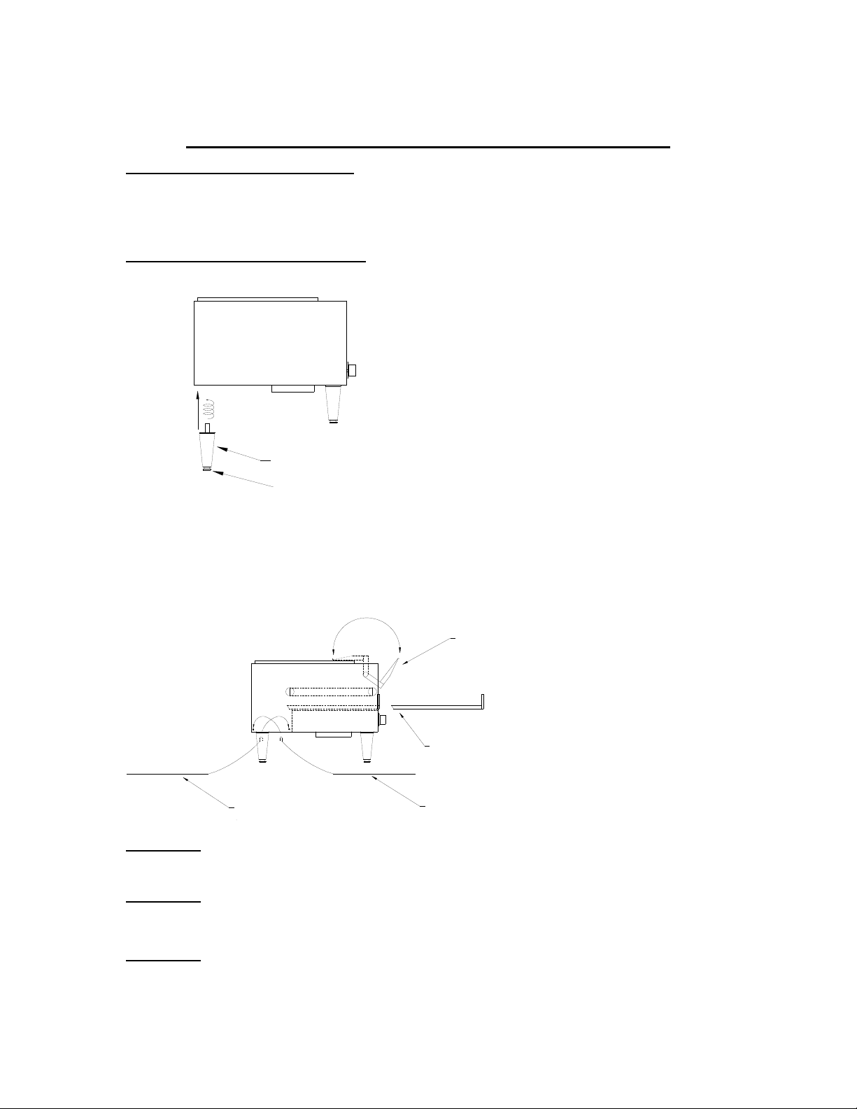
C. Place load and unload trays as shown below.
LOAD UP TRAY
HEAT REFLECTOR / CRUMB TRAY
(REAR DISCHARGE)
TOAST CHUTETOAST CHUTE
CAUTION: DO NOT OPERATE UNIT WITHOUT
CRUMB TRAY PROPERLY POSITIONED
AS THIS WILL CAUSE OVERHEATING IN THE
CONTROL BOX.
WARNING: MAKE SURE ALL INPUT POWER IS OFF BEFORE INSTALLING/REMOVING
WARNING
WARNING
ANY PARTS.
: BEFORE INSTALLING UNIT(S), CHECK WITH LOCAL POWER COMPANY TO
DETERMINE ACTUAL VOLTAGE AT JOB SITE. NEVER PLUG A 208-VOLT UNIT
INTO 240 VOLTS OR A 240 VOLT UNIT INTO 208 VOLTS.
: BE ABSOLUTELY SURE THE GROUND CONNECTION FOR THE RECEPTACLE
IS PROPERLY WIRED. NEVER CONNECT UNIT TO POWER WITHOUT
PROPER GROUND CONNECTIONS. IMPROPER GROUND MAY RESULT IN
SEVERE INJURY OR FATALITY.
REVISED 9/10/2008
MODELS T710(H, TW, TX) T714(H, TW, TX) S710(H) S714(H) B710H
OPERATION
Your Holman toaster may be equipped with a Power Saver Switch, details are as
follow;
Page 2
OPERATOR'S MANUAL
HOLMAN CONVEYOR TOASTERS
POWER SAVER
SWITCH
FULL
POWER
OFF
1/4 POWER
STAND BY
TOGGLE POWER SAVER
FULL POWER
OFFOFF
1/4 POWER
STAND BY
ROTARY POWER SAVER
USING YOUR POWER SAVER SWITCH
Power Saver
Switch Positions
FULL POWER- When in this position your unit is at Full Power and ready to use.
Adjust the Top and Bottom Variable Heat Controls and Conveyor
Belt Speed Control to your desired settings.
OFF-ROTARY: Two off positions are provided so that a single rotation to either
direction will result in the unit being turned OFF.
OFF-TOGGLE: The center position of the toggle switch turns the unit completely
OFF regardless of heat and speed control settings.
STANDBY- The standby position reduces the power to the unit to 1/4, and
therefore saves 75% of the energy consumption. In this position
your unit will stay warm and reduce the reheat time when switched
to Full Power to 20 to 30 seconds.
REVISED 9/10/2008
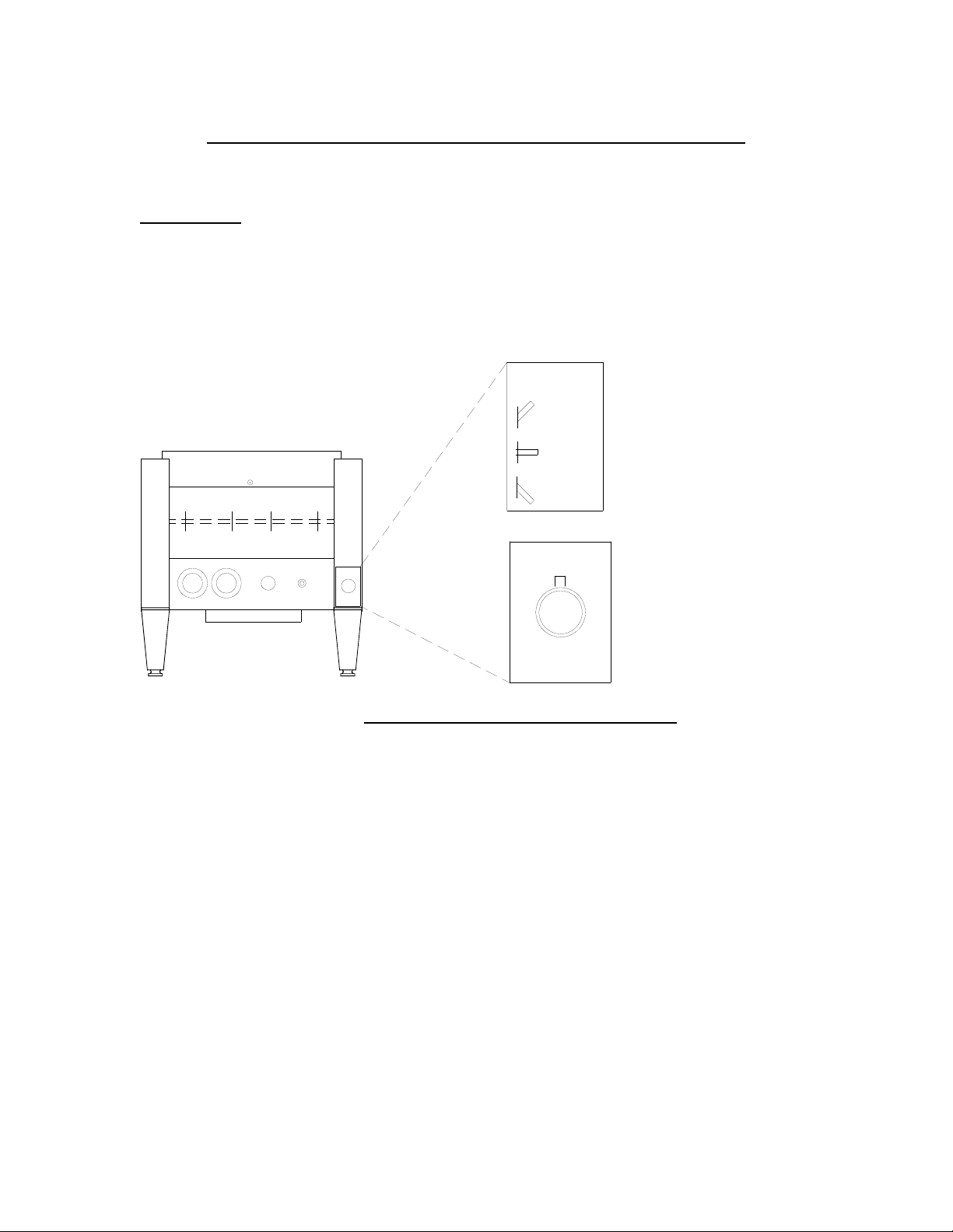
FULL KEY LOCKING COVER
FITS OVER CONTROLS AND
SIDE PANELS TO PREVENT
TAMPERING
OPERATOR'S MANUAL
HOLMAN CONVEYOR TOASTERS
MODELS S710(H), S714(H)
SECURITY COVER :
Your Holman models S710 and S714 are quipped
with a full front key locking cover (fig.1). This over fits
over the front and sides of the unit. The security
cover must be removed with a key in order to gain
access to the controls, side panels, legs and toast
chute to be removed.
To remove, unlock the cover using the key. Pull
locked side of cover out and away from the unit. The
right side will release at the same time.
HOLMAN
To replace the cover, Hook the right side of the cover
over the latch on right front of the unit while sliding
the left side of the cover over the lock. Secure cover
using key.
Page 2A
Fig. 1
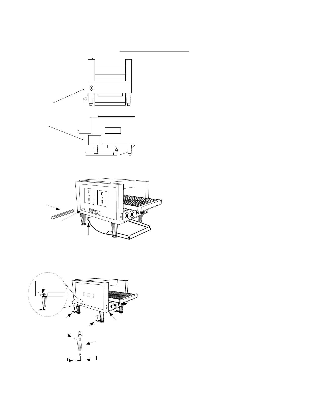
SECURITY TOAST
CHUTE MOUNTING
ROD
S710CHUT.WMF
Fig. 2
COTTER PIN
S710LEG.WMF
Fig. 3
S710LOK.WMK
TOAST CHUTE MOUNTING ROD
SLIDES THOUGH MOUNTING HOLE
IN CHASSIS AND THROUGH LOOP IN
TOP OF TOAST CHUTE
H
O
L
M
A
N
SECURITY COUNTER MOUNTING
BRACKET ATTACHES TO LEG FOOT
AND IS SECURED TO COUNTER
WITH A SCREW.
COTTER PIN
MOUNTING
BRACKET
LEG SCREWS
INTO THE BOTTOM
OF TOASTER
FOOT SCREWS
INTO BOTTOM
OF LEG
KEY LOCK
OPERATOR'S MANUAL
TOAST CHUTE ;
To install the toast chute (fig. 2), Remove the left side
panel by removing two screws and pulling the top
part of the panel out while lifting up. Remove the
mounting rod by sliding it through chassis.
Next, place the toast chute beneath toaster as
shown. Line up the looped end of toast chute with
holes in the rear of toaster as shown. Insert mounting
rod through the holes in chassis and the toast chute
(If legs have not been installed, do so now).
Reinstall side panel and secure with screws. Toast
chute is now ready for use.
LEGS :
To secure the toaster to the counter (fig.3), Remove
both side panels by removing two screws and pulling
the top of the panel out while lifting up. Unscrew the
foot of each leg and slide counter-mounting brackets
onto the legs. Screw the foot back onto each leg and
install legs onto the toaster. Place the small cotter pin
through the holes in threaded portion of each leg.
Secure the mounting brackets to the counter with a
screw or bolt. Reinstall both side panels and secure
with screws.
NOTE: Security models are not supplied with a
power saver switch.
REVISED 9/10/2008
PAGE 3
 Loading...