

Page 1
OWNERS GUIDE TO INSTALLATION
!
!
!
AND OPERATION
Fully Automatic
Water Softeners
Models S15DC29DR and S15DC39DR
FW0782
0211
Supersedes
0410
SAFETY INFORMATION
• Read the instructions carefully and learn the specific details
regarding installation and use. Failure to follow them could
cause serious bodily injury and/or property damage.
• Make certain the electrical outlet is grounded by having it
checked by an electrician or by using a UL Listed Circuit analyzer. Units are furnished with 3-prong grounded plugs to
protect you against the possibility of electrical shock.
the ground prong and never splice or cut the electrical cord.
• The outlet must be within reach of the power cord. Do not
use an extension cord. Extension cords that are too long
or too light do not deliver sufficient voltage to the unit
and could present a safety hazard if the insulation were to
become damaged. The receptacle should be located four (4)
feet above the basement floor to guard against the possibility of immersion.
Do not under any circumstances remove
box before installing or servicing the unit. Do not plug in unit
or change fuses while standing on wet or damp surfaces and
do not touch any other metal surfaces while plugging in product or changing fuses. Plug unit in with one (1) hand while
keeping the other hand free.
• Check to be sure your power source is capable of handling
the voltage requirements of the unit. Plug into a dedicated
grounded receptacle which contains a fuse or circuit breaker
of 20 amps or less.
• All water treatment installations must conform to local
plumbing, electrical and sanitation codes. These codes are
established for your protection.
the State of California to cause cancer and birth defects or
other reproductive harm.
Disconnect power at the main electrical
This product contains chemicals known to
Install Water condItIoner In an area protected from floodIng, raIn, dIrect
sunlIght, dust, snoW and freezIng. the Warranty does not cover damage
Incurred as a result of exposure to Weather.
021684
STAR WATER SYSTEMS | 95 North Oak St. | Kendallville, IN 46755 | starwatersystems.com
© Copyright 2011 Star Water Systems. All rights reserved.
1
Page 2

IMPORTANT NOTICE
Pay Special Attention to the Following Points
• Installation must be made within a protected area covered
from the elements and freezing. In areas where it is common practice to bury the unit in the ground, the unit must
be protected from direct sunlight, rain, dust, flooding, snow
and freezing. Failure to do so will void the warranty.
• Check plumbing inlet and outlet to ensure the proper flow
of water through the unit. Match plumbing inlet and outlet
with arrows located on the sides of the valve head and on
the bypass valve (especially if replacing an existing unit).
• Make sure the unit is plugged into a 115 volt grounded
outlet which contains a fuse or circuit breaker of 20 amps
or less.
• Do not run 1/2” I.D. semi-rigid drain tube over 20 running
feet. If over 20 ft., increase drain line tubing size to 3/4”
I.D. for the entire length of tube.
• Initially fill salt brine tank only 3/4 full with salt. (Do not
pack full.)
• If any red rust stains are apparent, mix Super Iron Out® with
the salt. As an alternative, there are types of salt available
that contain iron control agents.
• After installing the unit, manually regenerate unit, following the control valve instruction manual.
• Make sure control head is correctly set for your specific
water needs.
• If more than one unit is being installed, the regeneration/
back wash times should be staggered.
remember, your purchase Is an Investment and
needs to be maIntaIned properly.
If any parts are missing, damaged, unit does not seem to be
working properly, or if you have any questions call
1-800-545-2206 or 1-800-345-9422
STAR WATER SYSTEMS | 95 North Oak St. | Kendallville, IN 46755 | starwatersystems.com
© Copyright 2011 Star Water Systems. All rights reserved.
2
Page 3
TYPICAL INSTALLATIONS AND EQUIPMENT LOCATION
LOCATE WATER CONDITIONING EQUIPMENT CORRECTLY:
1. Select the location of your water softener with care.
Various conditions which contribute to proper location
are as follows:
2. Locate as close as possible to water supply source.
3. Locate as close as possible to a floor or laundry tub drain.
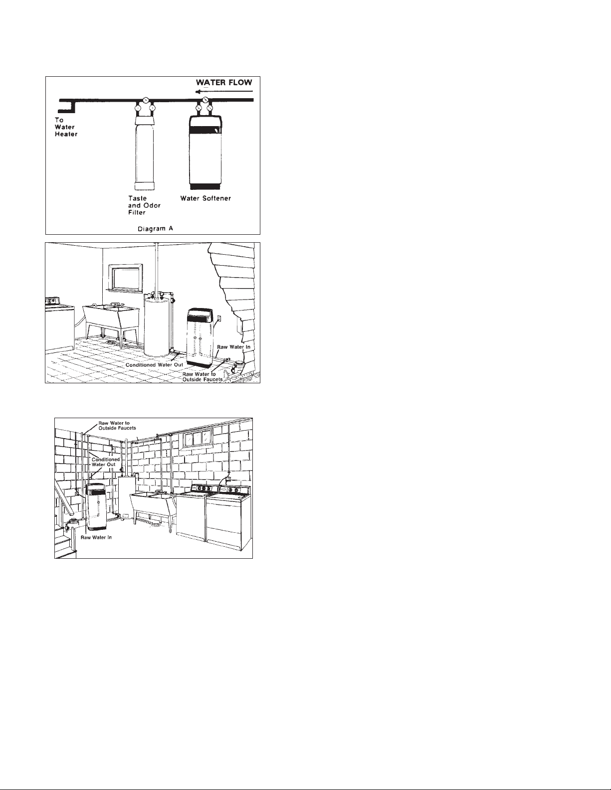
4. Locate unit in correct relationship to other water conditioning equipment, if required. (See Diagram A. for well
water applications or Diagrams B for city water applications.)
5. Select location where floor is level. If floor is rough and/or
uneven, you can level by placing cabinet or tanks on 3/4”
plywood, and shim to level as needed.
6. Locate the softener in the supply line BEFORE the water
heater. Temperatures above 100°F (38°C) will damage the
softener and void the factory warranty.
Install water conditioner in an area protected from flooding,
rain, direct sunlight, dust, snow and freezing. The warranty
does not cover damage incurred as a result of exposure to the
weather.
7. Allow sufficient space around the installation for easy
servicing.
Diagram B - Typical first floor installation for utility
room or breezeway, where floor drain exists.
8. Provide a non-switched 110/120V, 60Hz power source for
the control valve.
Diagram B - Typical basement installation uses overhead piping with floor or wash tub drain outlet.
© Copyright 2011 Star Water Systems. All rights reserved.
STAR WATER SYSTEMS | 95 North Oak St. | Kendallville, IN 46755 | starwatersystems.com
3
Page 4
EASY INSTALLATION INSTRUCTIONS
STEP I - PREPARE THE SOFTENER
1. Install the unit in the water line ahead of the water heater, close to a drain and a 115 volt grounded outlet , on a
flat surface. NOTE: Make sure electric outlet is grounded
and cannot be turned off by a wall switch or pullchain.
Install unit in an area protected from the elements and
freezing.
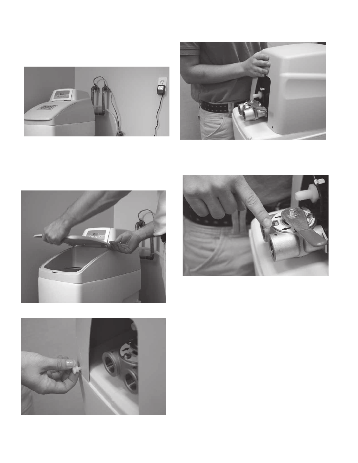
4. Slide upper hood assembly to front of unit. NOTE: There
are wires connecting display hood to control valve. Do
not move assembly further than shown as wires will
become tight and pull away from display panel.
2. Remove the salt compartment cover.
3. Remove two thumb screws
© Copyright 2011 Star Water Systems. All rights reserved.
STAR WATER SYSTEMS | 95 North Oak St. | Kendallville, IN 46755 | starwatersystems.com
5. Check inlet and outlet for correct water flow, matching
arrows on valve head and on bypass valve (especially if
replacing an existing unit). CAUTION: Install in direction
of arrows.
4
Page 5

EASY INSTALLATION INSTRUCTIONS
STEP II - PREPARE THE PLUMBING
1. Close main water supply shut-off valve.
Soft water
MAIN WATER PIPE
Control
Valve
From
softener
outlet
To softener
inlet
Hard water
Hard water to
outside faucets
Inlet
Outlet
4. Above diagram shows proper plumbing installation. Water flowing right to left.
Control
Hard water
IL0636
CROSSOVER
Use if water supply flows
from the left
Valve
Soft water
2. Open nearest faucet to relieve pressure and drain
plumbing lines.
3. On a new installation not already plumbed for a water
softener, cut out section of main water supply line
downstream from the supply shutoff, at position softener
is to be installed.
To softener
inlet
Inlet
Outlet
5. Above diagram shows proper plumbing installation.
Water flowing left to right.
NOTE: Softener will not work if connected to plumbing
incorrectly. Double check water flow for proper installa-
tion.
IL0637
STAR WATER SYSTEMS | 95 North Oak St. | Kendallville, IN 46755 | starwatersystems.com
© Copyright 2011 Star Water Systems. All rights reserved.
5
Page 6

EASY INSTALLATION INSTRUCTIONS
STEP III
CONNECTING AND STARTING SOFTENER
1. Connect the plumbing fittings to manifold and tighten.
Use thread tape. CAUTION: Do not overtighten, as damage to manifold and/or valve may result. Do not sweat fittings onto unit, as heat may damage components.
4. Typical drain line with proper air gap.
Note: An air gap is required by most local plumbing
codes to prevent waste water back ow. Check and follow your local codes.
2. Press 1/2” ID plastic tubing (included) onto drain line hose
barb until snug and secure with a hose clamp (not included). NOTE: Do not run 1/2” drain line over 20 ft. If over 20
ft., increase tube size to 3/4”
3. Make sure the bypass valve is in the service position as
shown above. Rotat handle 90 degrees to go into the
bypass position, and close off the valve when needed.
© Copyright 2011 Star Water Systems. All rights reserved.
STAR WATER SYSTEMS | 95 North Oak St. | Kendallville, IN 46755 | starwatersystems.com
5. Reinstall upper hood assembly. NOTE: Take care not to
move assembly further than necessary as control panel
is connected to control valve by wires.
6. Reinstall two thumb screws that were removed earlier.
6
Page 7

EASY INSTALLATION INSTRUCTIONS
7. Install 1/2” ID tubing (included) to the overflow hose
barb located on the side near the back of the softener
cabinet and run to a suitable drain. Do not connect to
drain line off of softener.
10. Draw a 5 gallon bucket of water to be used in the
brine tank.
8. Typical finished installation using rigid copper pipe.
9. Slowly open main water supply shut-off valve. CHECK
FOR LEAKS! Close previously opened faucet (item 2,
page 6) after air has stopped coming out of faucet.
11. Pour the 5 gallon bucket of water into the brine tank.
12. Measure 1-1/2 oz of chlorine bleach and pour solution
directly into the brine tank.
STAR WATER SYSTEMS | 95 North Oak St. | Kendallville, IN 46755 | starwatersystems.com
© Copyright 2011 Star Water Systems. All rights reserved.
7
Page 8

EASY INSTALLATION INSTRUCTIONS
13. Pour salt into compartment. Fill about 3/4 full initially.
Do not pack full. This is also where iron control agents
will be put if you have rust stains.
16. Proceed to Page 10 for Instructions to:
a. Set Time of day
b. Set Gallons
c. Start Regeneration (Step D2-b)
Adding a taste & odor filter will eliminate chlorine and
other chemicals as well as polishing the water used throughout the entire household. Install the whole house filter by
connecting to the softener outlet plumbing.
14. Replace brine cabinet lid.
15. Plug adapter from control valve into 115V grounded
electrical outlet. Make certain that outlet is supplied
with power at all times. Make sure area is dry before
plugging the unit in.
© Copyright 2011 Star Water Systems. All rights reserved.
STAR WATER SYSTEMS | 95 North Oak St. | Kendallville, IN 46755 | starwatersystems.com
8
Page 9

MAINTENANCE
1. SALT REFILL - During each regeneration of the water softener, a specific amount of salt is consumed, thus requiring
periodic replenishment. The frequency of the replenishment depends on the regeneration schedule. Always
replenish salt before the supply is exhausted to ensure a
continuous supply of softened water.
We suggest using pellet type salt or grade A rock salt
that contains no dirt or sediment. Fill tank about 3/4 full.
Do not pack full. Do not use block salt. Potassium chloride, a salt substitute, can be used.
2. Preventing iron fouling of mineral bed - If iron is present
in the water supply, the softener will eventually become
iron fouled, resulting in reduced softening capacity and
rust stained fixtures. Mixing one or two ounces of Super
Iron Out® or similar iron cleaner with every 80 lbs. of
salt added to the brine compartment will minimize these
problems. As an alternative, there are types of salt available on the market that contain iron control agents.
3. Brine compartment clean out - To prevent service prob-
lems, the salt compartment should be emptied of accumulate. This clean out should be done when the salt
level is low or exhausted.
To eliminate the need of removing the brine tank (two
tank models) or the entire unit (single tank models), use
a wet/dry vacuum cleaner to empty the old brine water.
Once emptied, clean dirt from the salt compartment.
Add 5 gallons of water and new salt.
4. Periodically check time of day setting - Power outages
will cause time of day timer setting to become incorrect.
To reset, refer to “Setting the Control Valve.”
5. Change of operating conditions - Should your family size,
your water usage habits or your water quality change,
the regeneration program setting may have to be adjusted. Do not lower salt setting.
PREVENTING WATER CONDITIONERS
OR FILTERS FROM FREEZING WHILE IN
STORAGE
NOTE: The warranty does not apply to damage due to freezing, nor is the manufacturer responsible for or assume any
liability for breakage, missing parts or consequential damage
that results from placing the unit into storage.
1. Plan Ahead! Placing the unit into storage should be done
when the salt level in the brine tank is low but NOT completely exhausted.
2. Immediately before storage and before the salt is completely exhausted, manually start the regeneration process and allow the unit to automatically go through all of
the regeneration cycles.
3. Place the unit into the bypass position, depressurize and
disconnect the plumbing from the control valve.
4. Remove the control valve from the mineral tank by turning counterclockwise.
5. Shake as much water out of the valve as possible and store
in an open, dry area. Place any loose fittings in a plastic
bag and tape to the valve.
6. Syphon water from the mineral tank, inserting a hose
into and down the distributor tube. This tube is in the
middle of the mineral tank and can be seen once the
valve is removed.
7. Using a wet/dry vacuum cleaner, empty the brine tank/salt
compartment of brine water. Then remove as much of
the remaining salt as possible. CAUTION: Salt will become
encrusted if allowed to remain in the brine tank.
8. Using two (2) people, place mineral tank or cabinet on its
side on the floor, using caution as the cabinet or mineral
tank will break if dropped or not handled carefully.
CAUTION: Water from the mineral tank will cause damage
to carpeting, vegetation, furniture, etc. The manufacturer
of the equipment is not responsible, and assumes no
liability for such damage.
9. DO NOT stand the unit upright until it is to be placed
back into service. To do so will allow remaining moisture
to settle to the bottom of the mineral tank, expand when
freezing, thereby splitting the tank.
10. To place the unit back into service, refer to installation
and control valve instructions.
STAR WATER SYSTEMS | 95 North Oak St. | Kendallville, IN 46755 | starwatersystems.com
© Copyright 2011 Star Water Systems. All rights reserved.
9
Page 10

SETTING THE CONTROL VALVE
IL1033
FOLLOW THE INSTRUCTIONS STEP BY STEP!
DO NOT DEPRESS THE BUTTONS OUT OF SEQUENCE!
Parameter
Display
Error/
Information
Icon
Service
Icon
Programming
Icon
Figure 1
Normal display
alternates between
time of day and gallons
of water remaining
until regeneration
Extra Cycle
Button
A. SETTING THE CURRENT TIME OF DAY
1. Plug unit into a 115 volt grounded outlet that is
independent from a wall switch or pull chain. When
unit is plugged in, display should activate.
2. Press and hold either the Up or Down buttons until
the programming icon replaces the service icon and
parameter display reads TD.
3. Adjust the displayed time with the Up and Down
buttons. Note the PM indicator on the display.
4. When the desired time is set, press the Extra Cycle
button to resume normal operation. The unit will
also return to normal operation after 5 seconds if no
buttons are pressed.
Up
Button
Data
Display
Indicator
Down
Button
PM
Flow Indicator
x1000 Indicator
IL1030
IL1032
3. Press the Extra Cycle button. Use this display to
adjust the Regeneration Time. This option setting is
identified by “RT” in the upper left hand corner of
the screen. The setting was factory set for 2:00 AM.
The regeneration time can be adjusted by pressing
the up or down buttons. Note the PM indicator on the
display. Regeneration time is when the unit will begin
a regeneration cycle. This should be set to a time of
minimum water usage.
IL1031
B. SETTING DAY OVERRIDE, REGENERATION TIME
AND FEEDWATER HARDNESS
1. Press the Up and Down buttons for five seconds while
in service, and the time of day is NOT set to 12:01 PM.
2. Use this display to verify the Day Override. This option
setting is identified by “DO” in the upper left hand
corner of the screen. The setting was factory preset to
display “OFF” for all water softener units. If required,
adjust valve by pressing the up and down buttons.
© Copyright 2011 Star Water Systems. All rights reserved.
STAR WATER SYSTEMS | 95 North Oak St. | Kendallville, IN 46755 | starwatersystems.com
4. Press the Extra Cycle button. Use this display to
adjust the Feed Water Hardness. This option setting is
identified by “H” in the upper left hand corner of the
screen. This value is your water hardness in grains per
gallon from your water analysis form.
10
Page 11

IL1034
To obtain information concerning the hardness of the
water to be treated, purchase the 136958 mail-in test kit
from your dealer. Return a sample of untreated water in
the bottle provided with the kit to the laboratory. The water
sample will be analyzed and the results returned to you.
NOTE FOR WATER WITH RUST STAINS:
If iron is present in the water as evidenced by red stains
on clothes, fixtures, toilets, etc., add 12 grains per gallon
to the previous water hardness setting and have water
retested.
Mix 2 ounces of Iron Out® or similar iron cleaner with
every 80 lbs. of salt used (if above 5 PPM of iron, increase
to 4 oz.) or use a salt with iron control agent.
IL1131
3. If power fails while the unit is in regeneration, the
control will save the current valve position before
it shuts down. When power is restored, the control
will resume the regeneration cycle from the point
where power failed. Note that if power fails during
a regeneration cycle, the valve will remain in it’s
current position until power is restored. The valve
system should include all required safety components
to prevent overflows resulting from a power failure
during regeneration.
4. The control will not start a new regeneration cycle
without line power. If the valve misses a scheduled
regeneration due to a power failure, it will queue a
regeneration. Once power is restored, the control will
initiate a regeneration cycle the next time that the
Time of Day equals the programmed regeneration
time. Typically, this means that the valve will
regenerate one day after it was originally scheduled.
If the treated water output is important and power
interruptions are expected, the system should be set
up with a sufficient reserve capacity to compensate for
regeneration delays.
5. Press the Extra cycle button. Use this display to set the
system reserve capacity. It has been factory pre-set at
20 and should not need any modifications.
6. Press the extra cycle button to exit this mode and
return to normal display.
C. EXTRA REGENERATION
1. The unit is factory preset to regenerate at 2:00 AM.
2. To initiate an extra regeneration, two methods are
available:
a. Regeneration at next Regeneration Time
1. Press the Extra Cycle button. The service
icon will flash to indicate that a regeneration
is queued. Unit will regenerate at next
regeneration time set in valve.
2. To cancel a queued regeneration, press the
Extra Cycle button.
b. Immediate Regeneration
1. Press and hold the Extra Cycle button for five
seconds
2. Valve will begin regeneration momentarily.
D. CONTROL OPERATION DURING A POWER FAILURE
1. The control includes integral power backup. In the
event of power failure, the control shifts into a powersaving mode. The control stops monitoring water
usage, and the display and motor shut down, but
it continues to keep track of the time and day for a
minimum of 48 hours.
2. The system configuration settings are stored in a
non-volatile memory and are stored indefinitely with
or without line power. The Time of Day flashes when
there has been a power failure. Press any button to
stop the Time of Day from flashing.
© Copyright 2011 Star Water Systems. All rights reserved.
STAR WATER SYSTEMS | 95 North Oak St. | Kendallville, IN 46755 | starwatersystems.com
11
Page 12

WATER SOFTENER TROUBLE SHOOTING
JUST INSTALLED UNIT AND WATER IS NOT SOFT
WHAT TO CHECK HOW TO CORRECT
Has unit been properly installed Re-read instructions to see that all steps were followed.
Bypass in plumbing On a 3-way bypass valve system, open valves on piping coming
into and out of softener. The valve in between MUST be closed
and in good condition. Most units include a bypass valve which
is connected to the control valve. Make certain that it is in the
service position.
Is unit piped in backwards Check arrows where pipe threads into valve head and make sure
water is flowing consistent with the direction arrows are pointing.
Hot water tank hardness Allow sufficient time for hardness that has built up in your water
heater and pipes to run through system. Repeated flushing of the
water heater tank can also be done.
Is there resin in tank Softeners ship with resin already in the tank. Make sure the resin
has not been emptied or dumped. Put a trouble light behind resin
tank and you should be able to see the resin through the mineral
tank. The tank should be approx. 2/3 full.
Valve head is not working correctly and causing water
not to flow through softener
Softener has been undersized and does not effectively
remove the amount of hardness in your water
Water flow rate going through the softener is not allowing time for the unit to soften
*To depressurize the unit, refer to valve instructions for your particular unit.
Shut off water supply, de-pressurize the unit*, unscrew the valve
head from unit and exchange it.
Draw a sample of untreated water before it goes through the
softener and a sample of treated water after the softener. Have the
samples analyzed to see if any hardness is being removed.
Open an outside faucet and fill a measured bucket up with water
for 1 minute. The amount of gallons in the bucket tells you how
many gallons per minute are being run through the softener. Call
1-800-545-2206 to see what the GPM limit is on the specific unit
you have purchased. Add a flow control accessory to your unit if
needed.
WATER TASTES SALTY OR BRINE TANK FILLS WITH WATER
WHAT TO CHECK HOW TO CORRECT
Is backwash water flowing freely down to drain with an
air gap and no back siphoning
Brine salt tube and connections not allowing salt solution into mineral tank to regenerate
Injector or injector screen plugged Put softener in bypass position and de-pressurize the unit by put-
Put valve into “Backwash” position and follow water flow down
to drain. If over 20 ft., use 3/4” (or larger) drain tubing. Drain line
should be no more than 8 ft. lift.
Visually check tubing for cracks or kinks. Check fittings for proper
assembly and tightness as shown in the diagram.
Brass
Compression
Nut
Brass
Insert
Poly
Tubing
Plastic
Ferrule
IL0707
ting into “Backwash” position. There will be 2 screws on neck of
valve where the salt rinse line goes into softener, remove the 2
screws and clean screen and remove any chunks of salt, etc.
STAR WATER SYSTEMS | 95 North Oak St. | Kendallville, IN 46755 | starwatersystems.com
© Copyright 2011 Star Water Systems. All rights reserved.
12
Page 13

WATER SOFTENER TROUBLE SHOOTING
WATER WAS SOFT BUT NOW FEELS HARD
WHAT TO CHECK HOW TO CORRECT
No salt in brine tank Add salt to brine tank and maintain salt level above water level.
Manually initiate the regeneration cycle and allow softener to
totally go through all regeneration cycles.
Electrical service to unit has been interrupted Make certain that the power cord is plugged into a 115V grounded
outlet that cannot be turned off accidentally by a wall switch or
pull chain. Check for blown fuses. In case of electrical power outages, reset the time of day. Some valves utilize a battery - see
valve instructions for battery replacement.
Has softener valve head been programmed to regenerate after installation
Has the bypass been used and not connected back into
service
Salt is bridging in tank Salt in bottom of tank has hardened and is not allowing water/salt
Salt tube going from salt tank to mineral tank is plugged
or insufficient water flowing into brine tank
Brine salt line and connections not allowing salt solution into mineral tank to regenerate
See valve programming instructions. Was water properly tested
and diagnosed for correct setting? Have additional people moved
in or water usage increased?
Make sure the handle of the bypass valve is in the service position. On a 3-way bypass position, open the inlet and outlet valves
ad close the bypass valve.
mixture to get to the bottom of salt and consequently over to mineral tank. Do not fill salt tank completely (3/4 full). Use a stick or
broom handle and poke into salt, making sure it is broken up.
Put unit into “Brine Rinse” position, make sure salt water flows
uninterrupted from salt tank to mineral tank. Clean or replace
brine valve. Clean and unplug necessary line so water flows
uninterrupted.
Visually check tubing for cracks or kinks. Check fittings for proper
assembly and tightness as diagrammed.
Brass
Compression
Nut
Brass
Insert
Poly
Tubing
Plastic
Ferrule
IL0707
Injector or injector screen is plugged Put softener in “Bypass” position and de-pressurize by putting
in “Backwash” position. There are 2 screws on valve neck where
salt line tube enters softener. Remove screws, clean screen and
remove chunks of salt, etc.
Line pressure is too low
Is backwash water flowing freely down to drain with an
air gap and no back siphoning
Line pressure must be at least 20 PSI at all times.
Put valve into “Backwash” position and follow water flow down
to drain.
Too much iron or tannins have fouled the bed A water softener is only effective for up to limited amounts of iron
and yellowish colored tannins. Draw water before it goes into and
after it flows through softener. Have both samples tested to see
if iron is being removed or if mineral bed is already coated and
fouled.
Salt level setting on valve head is set too low Verify salt setting and adjust as necessary (consult factory at 1-
800-742-5044)
Valve head or timer is not cycling Shut off water supply, de-pressurize tank*, unplug unit and
replace valve head motor.
Has softening mineral been exposed to freezing Freezing weather causes the resin to mush and become ineffec-
tive. Replace resin, properly insulate and shield unit from direct
elements and freezing temperatures.
Leak in distributor tube Check for cracks in distributor tube. Check o-ring and tube inlet in
bottom of valve. Replace if necessary.
STAR WATER SYSTEMS | 95 North Oak St. | Kendallville, IN 46755 | starwatersystems.com
© Copyright 2011 Star Water Systems. All rights reserved.
13
 Loading...