

Page 1
NOTICE TO INSTALLER: Instructions must remain with installation.
Manufacturers of . . .
“Quality Products since 1866”
95 N. Oak St. • Kendallville, IN 46755
1-800-345-9422
MODEL S1585
BATTERY BACKUP PEDESTAL SUMP PUMP
PREINSTALLATION CHECKLIST
FW0264
1008
Supersedes
0305
1. Inspect your pump. Occasionally, products are dam aged during shipment. If the unit or any of the parts are dam aged, contact your dealer
before us ing.
2. Read all the installation instructions regarding in stall ing and start up. Retain for future ref er ence.
SEE BELOW FOR LIST OF WARNINGS
1. Testing for Ground. As a safe ty mea sure each elec tri cal outlet
should be checked for ground using an Underwriters Laboratory
list ed cir cuit ana lyzer, which will indicate if the power, neu tral and
ground wires are correctly con nected to your out let. If they are
not, call a qualifi ed licensed electrician.
2. For your pro tec tion always dis con nect the pow er supply from its
power source before handling the com po nents of your DC back up
pump or the pri ma ry pump.
3. Installation and checking of elec tri cal cir cuits and hard ware should
be per formed by a qualifi ed, li censed electrician.
SEE BELOW FOR LIST OF CAUTIONS
4. All elec tri cal and safety codes must be fol lowed in ad di tion to the
National Electrical Code and all applicable local codes.
5. It is the owner’s responsibility to check the bat tery
and bat tery connection at least once a month. Bat-
ter ies con tain acid and cau tion must be taken when
han dling.
6. Risk of electric shock - These pumps have not been investigated
for use in swimming pool areas.
7. According to the state of California (Prop 65), this product contains
chemicals known to the state of California to cause cancer and
birth defects or other reproductive harm.
1. Make sure there is a properly ground ed 115V re cep tacle avail-
able. Do not use primary pump cir cuit. The location must be within
6' of the control box and battery. The power supply for your DC
control system plugs directly into the 115V outlet. DO NOT USE
AN EX TEN SION CORD.
2. Make sure the 115V electrical supply circuit is equipped
with fuses or circuit breakers of prop er capacity.
3. DC emergency pumps are de signed for han dling clear water. Do
not use in septic tanks to pump ef fl u ent or sew age pits to pump
sewage.
95 N. Oak St. • Kendallville, IN 46755 • 1-800-345-9422
© Copyright 2008. All rights reserved.
4. Repair and service of your DC backup sys tem should be per formed
by an authorized service station.
5. The installation of DC automatic back up pumps re quires the use
of a variable level fl oat switch for operation. It is the responsibility
of the installing party, to ensure that the teth ered fl oat switch will
not hang up on the pump ap pa ra tus or pit pe cu li ari ties and is
secured so the pump will turn “on” and “off”. It is recommended
that the pit be 18" in diameter or larger to ac com mo date both a
pri ma ry and a DC backup pump.
1
Page 2
Ten Helpful Hints For Easy Installation
1. Remove all debris from pit before installation.
2. Use a deep cycle battery only. Refer to battery de scrip tions on page 6.
3. Be sure the pump is on a fi rm, level surface.
4. Install a serviceable check valve in the discharge
line.
5. Test the unit immediately after installation. Refer to
STEP 6.
Do’s And Don't’s For Installing A Unit
1. DO read all installation material with the pump and
charger.
2. DO inspect unit for any visible damage caused by shipping. Contact dealer if unit appears to be damaged.
3. DO clean all debris from the pit.
4. DO always disconnect pump from power source before
han dling. DO always connect to a separately protected
and prop er ly grounded ground fault protected circuit.
DO NOT ever cut, splice or damage power cord. DO
6. The battery & charger should be placed on a shelf.
7. Check fl oat On/Off levels per STEP 2 of instructions.
8. Apply grease to the Positive and Negative terminals
of the battery to prevent corrosion.
9. Check the battery water level once a month and add
distilled water as necessary.
10. Obtain model number, date code and in stal la tion in struc tions be fore calling factory.
NOT carry or lift pump by its power cord. DO NOT
use an extension cord with the Aquanot®. DO NOT
lengthen battery/pump leads.
5. DO install union check valve (see step 3) in the dis charge line. DO NOT use a dis charge pipe smaller
than the rec om mend ed pump discharge sizes.
6. DO test pump immediately after installation to be sure
that the system is working properly.
7. DO review all applicable local and national codes and
verify that the installation conforms to each of them.
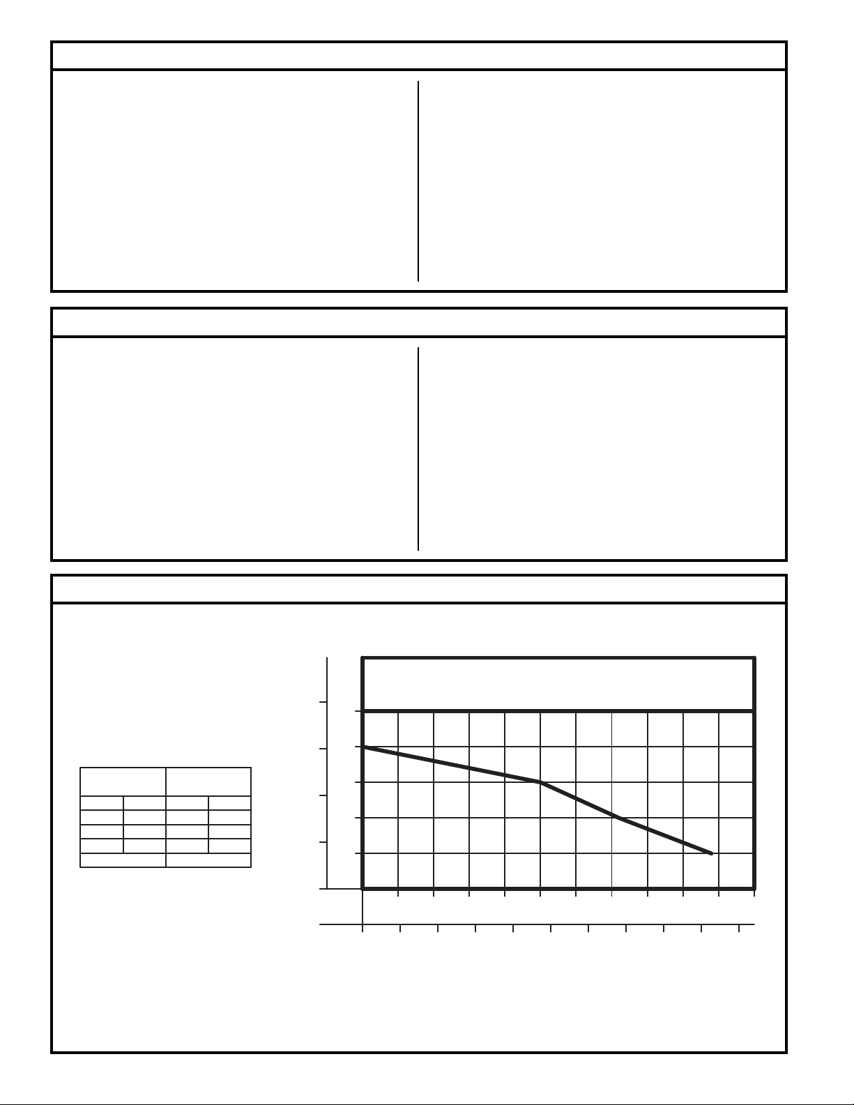
Performance Characteristics
METERS
FEET
8
TOTAL DYNAMIC HEAD/FLOW
PER MINUTE
EFFLUENT AND DEWATERING
MODEL
Feet
Meters
5
10
15
Shut-off Head:
1.5
3.0
S1585
Gal.
49
36
254.6
20 ft.(6.1m)
Liters
186
136
95
25
20
6
15
4
TOTAL DYNAMIC HEAD
10
2
5
0
GALLONS
LITERS
5
020
Note: Aquanot® II (Model S1585) data was de vel oped with the charger supplying DC power to the pump.
PUMP PERFORMANCE CURVE
MODEL S1585
2010 15 25
40 60 80 100
FLOW PER MINUTE
30
120 140 160 180
4035 45 50
55
200
011922FW
© Copyright 2008. All rights reserved.
2
Page 3
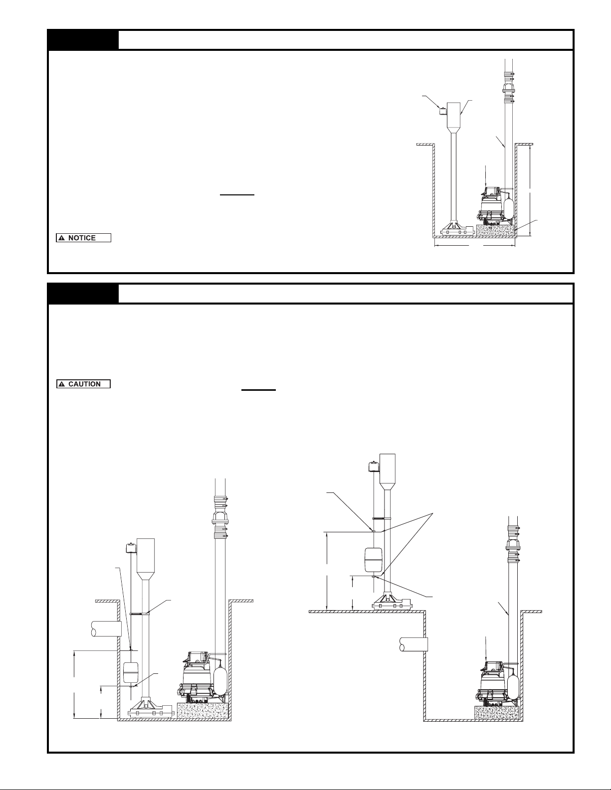
STEP 1 Placement of the Pump in the Pit
Note: If your pit has a cover, then it will have to be modifi ed to accept the
Aquanot®.
1.1) Inspect the pit for debris and clean as nec es sary
ON/OFF SWITCH
PUMP MOTOR
1.2) Place the pump in the pit making certain that it is on a stable level
surface. Refer to Figure 1.1.
MAIN DISCHARGE
LINE
IMPORTANT: If this pump is to be used as a backup to your primary pump,
then make certain that there is no interference between the two pumps.
The motor is not watertight. It should NEVER be below fl oor level.
If necessary, bricks or similar materials, can be placed under the Aquanot®.
This product is meant to be used as a battery backup pump to
your primary pump only. Consult factory for advice before installing this unit
as a primary pump.
PRIMARY PUMP
18 MIN.
Figure 1.1
22 MIN.
BRICK OR SIMILAR
MATERIAL
SK1775
STEP 2 Float Stop Adjustment
2.1) With the pump in the pit, measure the desired fl oat stop on/off positions as shown in Fig. 2.1. These two dimen-
sions will de ter mine the on/off levels of the pump. The spacing between the upper and lower stops will de ter mine
the amount of water removed from the pit.
Note: It may be necessary to raise the fl oat rod guide to adjust the stops to the dimensions determined in Step 2.1.
The fl oat rod guide should NEVER be between the upper and lower stop.
2.2) Remove the pump from the pit and adjust the fl oat stops as necessary. Tighten all screws.
Note: If a brick, or similar material has been used to raise the pump in the pit, it will be necessary to account for the
thickness of the brick.
UPPER
STOP
"ADJUST" ON/OFF POSITIONS
"ON"
HEIGHT
UPPER
STOP
"OFF"
HEIGHT
FLOAT ROD
GUIDE
LOWER
STOP
"ON"
HEIGHT
"OFF"
HEIGHT
LOWER
STOP
MAIN DISCHARGE
LINE
PRIMARY PUMP
SK1776 SK1777
Figure 2.2Figure 2.1
© Copyright 2008. All rights reserved.
3
Page 4

STEP 3 Installation of the Discharge Piping
3.1) Assemble the discharge pipe into the pump as shown in
CHECK VALVE
Figure 3.1.
IMPORTANT: In order for this installation to work properly, a check
valve must be installed onto the discharge line.
( Recommend the following Star check valve, #KH34.
Some local codes require union check with ball valve.
STEP 4 Electrical Connections
4.1) Complete electrical connections as shown in Fig ure 4.1.
4.2) Proceed to STEP 6.
Do not place battery or charger directly on ground. If the
battery or charger must be placed directly on the ground, then place
a piece of wood between the units and the ground. Do not put the
charger on top of the battery.
BATTERY
RED LEAD
TO POSITIVE(+)
BLACK LEAD
TO NEGATIVE(-)
ALARM
MAIN
DISCHARGE
LINE
PRIMARY PUMP
Figure 3.1
POSITIVE(+)
BATTERY TERMINAL
RED LEAD
TO POSITIVE(+)
OR
NEGATIVE(-)
BATTERY TERMINAL
BLACK LEAD
TO NEGATIVE (-)
CHARGER
MOTOR
CHECK VALVE
MAIN
DISCHARGE
LINE
PRIMARY PUMP
SK1778
OUTLET
SWITCH
CUT AWAY OF SUMP PIT
Figure 4.1
STEP 5 Testing of Pump Operation
6.1) Unplug the primary pump so that it does not start.
6.2) Fill pit with water until the Aquanot® starts.
6.3) Verify that the pump starts and stops at the desired on/off points.
6.4) Verify that there are no leaks in the discharge line.
6.5) If adjustment is necessary, raise or lower the appropriate stop(s) according to STEP 2.
IMPORTANT: Spacing between upper and lower stops determine amount of water removed from pit.
6.6) If the pump is not operating properly after following the above steps, refer to the Troubleshooting guide on page 8.
6.7) When fi nished testing plug primary pump back into AC receptacle.
SK1783
© Copyright 2008. All rights reserved.
4
Page 5

Operation of the Aquanot® Charger
The charger automatically monitors and charges your battery. In the event of a power outage the pump will be powered by the
battery. Once line power is restored, the charger will recharge the battery. If there is a failure of the primary pump, the charger will
supply power to the pump through the battery if line power is present; otherwise, the battery will take over until the problem has
been corrected.
The lights on the front panel of the charger indicate the state of system:
The red light: Indicates that AC line power is present.
The green light: Indicates that the battery is charged to 12V DC*.
During periods of extended power outage the charge on the battery may drop below 12V DC which would cause the green
light to go out. This is normal. The green light will be illuminated once the charger restores the voltage level to 12V DC.
The yellow light: Indicates that the battery is charged above 8V DC.
If the yellow light is not illuminated, it indicates that the charge on the battery is below 8V DC. If the line power is out, the pump
may have depleted the battery due to normal operation. If there has been no power outage and the primary pump is working
properly, it may indicate that the battery is defective or that the controller is defective. Refer to the Troubleshooting guide on
page 8 for further instructions.
If the Green and Yellow lights fl ash intermittently, refer to Section G in the Trouble Shooting Guide on page 8.
*Voltage is only one indicator of the state of the battery, and does not refl ect the true condition of the battery. Use a hydrometer to
more accurately determine the condition of the battery.
Operation of the Audible Alarm
All Aquanot® pump systems are equipped with an alarm which sounds when the pump is activated. The alarm will automatically
silence when the pumping cycle is completed.
Activation of the audible alarm indicates that the primary pump has failed or line power to the primary pump is not present. When-
ever the alarm is activated the primary pump and outlet should be inspected.
The On/Off switch, located on the side of the alarm enclosure, allows the audible alarm to be turned off, however, this practice is
not recommended. Verify that the alarm switch is in the “on” position, by manually turning the pump “on”.
The Aquanot® Battery
There are millions of batteries manufactured each year, so it is impossible to guarantee consistent quality. A defective battery will
never become fully charged and may damage the circuits of the charger. It is for this reason that Star offers its own MaintenanceFree AGM Battery, which will power the pump for over 3½ hours without AC power. This time is based on continuous pumping at 10’
of static head. Actual times will vary depending on static head, volume of water entering the pit, and the condition of the battery.
When purchasing a battery for the Aquanot® II unit, follow these recommendations:
• Use a B.C.I. size 27 deep-cycle battery, 175 minute reserve capacity, or larger.
• Do NOT use a “maintenance-free” battery unless it is Gel-fi lled or AGM.
• Replace your battery every 3 years.
• Do not let corrosion build up on the battery terminals.
• Do not place your battery on a concrete fl oor where it will discharge faster.
• To check specifi c gravity, follow the instructions on a hydrometer (not applicable for Gel or AGM batteries).
PROTECT YOUR WARRANTY:
• Water level in batteries must be checked once a month (not applicable for Gel or AGM batteries).
NOTE: The purchase of an Aquanot® battery from Star Water Systems will extend the limited warranty to three years from date of
installation. The three year limited warranty is valid only when a complete system is purchased and used as a backup to a primary
dewatering system. A complete system includes the Aquanot® II Model S1585 and Aquanot® battery.
© Copyright 2008. All rights reserved.
5
Page 6

Illustrated Parts Breakdown
20-MODEL S1585 COMPLETE PUMP
REF.
NO.
1 Motor Brushes 2 013878
2 Pump Alarm 1 012485 012485
3 Pump Switch 1 017205 017205
4 Float Kit & Cable 1 012709 012709
5 Lead Wires 1 012401 012401
6 Terminal Spade 1 004442 004442
7 Terminal Ring 1 011939 011939
8 Pump Motor 1 013873 013873
9 Column 1 011942 011942
10 Adapter, Drive 1 011940 011940
11 Shaft 1 011944 011944
12 Head w/Brass Bearing 1 012137 012137
13 Washer, Thrust 1 002140 002140
14 Impeller 1 011945 011945
15 Base Plate 1 012138 012138
16 Screws 8 012118 012118
17 Guide, Float Rod 1 003903 003903
18 Battery Charger 1 015409 015409
19 N/A N/A
20 Pump S1585 1 015407 015407
21 Float 1 012707 012707
22 Stop, Float 2 054085 054085
23 Rod, Float 1 012706 012706
24 Screws 1 003925 003925
*Advise motor Leeson or CIM.
DESCRIPTION QTY
MODEL: S1585-A S1585-B
03/02
to
12/04
1/05
to
Current
*Consult
Factory
21
1
8
9
2
10
3
11
4
17
24
5
12
13
7
6
14
15
16
TERMINAL
DETAIL
22
23
18
SK1786FW
Carbon Monoxide Detectors
Whether you have an Aquanot® Battery Backup Sump Pump System, or a competitive brand, all batteries give off gaseous by-
products when charging. Some of these by-products can produce a rotten egg odor. Also, some of these by-products can cause
a CO detector to falsely activate. In order to help prevent false activation, we recommend moving the battery as far apart from the
CO detector as possible or, if necessary, vent the battery to the exterior. We provide the previous statements only as guidelines
to help prevent false activation of the CO detector. In no way are they meant to supersede the instructions that accompany the
detector nor do they supersede advice from the CO detector manufacturer.
If the audible alarm associated with your CO detector is activated, we recommend the following actions:
1) Take immediate action for personal safety as recommended in the CO detector literature.
2) Contact the appropriate agency to determine if the CO is being produced by your furnace, water heater, or any other device
which uses natural gas.
3) If you are certain that no CO is being produced, then a charging battery may be producing gaseous by-products which are
causing the CO detector to activate. Contact the manufacturer of the CO detector, and ask for recommendations as to what
can be done to prevent the alarm activation.
© Copyright 2008. All rights reserved.
6
Page 7

REPLACEMENT PARTS LIST FOR:
AQUANOT® S1585 CHARGER
CHARGER
REF.
NO.
1 Fuse, In-line/Resetable/10 amp 1 012285
2 Cover, “S1585” Charger 1 011963
3 Screw, #10-32 X .375 Pan HD/Phillips/Self Tap/Zinc 6 011984
4 Transformer, “Aquanot®” 1 011967
5 Nut, Hex 10-32 HH Zinc 3 012129
6 Overload, 40 amp/12v/#54-240/“Aquanot®” 1 011968
7 Rectifi er, Asm “Aquanot®” 1 N/A
8 Base, Charger “Aquanot®”/Model S1585 1 012360
9 Nut, Kep 1/4-28 HH Zinc 3 N/A
10 Fastener,Rivet,Alum-#64 1-3/16 X .125 X .25 4 011966
11 Wire Asm-f-s(1)Wire 6"Lg/10ga 1 012288
12 Diode, IN1183A B1197 2 N/A
13 Circuit Board, “Aquanot®” 1 016787
14 Cord & Term “S1585” Charger 1 012297
15 Wire Asm-F-S(1)Wire 66” Lg/Red 1 012342
16 Wire Asm-F-R(1)Wire 66” Lg/Black 1 012341
17 Screw,#10-32 X.50 Pan HD/Phillips/Zinc 1 011929
18 Clamp,Strain Relief-cord #1200 1 011974
19 Clamp,Strain Relief-lead Wire-#1504 1 011975
20 Screw, #6-32X .438 RH PH TP 1 STZI 2 004644
21 Charger, 25A Model S1585 1 015409
22 Wire, Asm, 6” Long/Black, Crimped & Soldered 1 012449
DESCRIPTION QTY
Current
A
03/02
to
2
3
4
5
6
7
(OPTIONAL)
8
9
10
11
22
12 (OPTIONAL)
13
20
9
18
19
17
1
14
15 RED
16 BLACK
TO ORDER REPLACEMENT PARTS:
PLEASE FURNISH THE FOLLOWING INFORMATION:
• Part Number of Unit.
• Revision Letter.
• Part Number and De scrip tion of part.
© Copyright 2008. All rights reserved.
7
21
SK1841
Page 8

Troubleshooting Guide
CONDITION POSSIBLE CAUSE REMEDY
Low voltage, blown fuse open circuit. Have a qualifi ed electrician check fuse and cir cuit.
Impeller bound.
A PUMP WILL NOT START OR RUN.
B PUMP STARTS TOO SOON. Float “ON” point is adjusted too low. Refer to STEP 2.
C PUMP WILL NOT SHUT OFF.
PUMP OPERATES BUT DELIVERS
D
LIT TLE OR NO WATER.
RED LIGHT ON CHARGER (MODEL
E
585) IS OUT.
F RED LIGHT FLASHING (MODEL 585). The charger fan may be defective. Have a qualifi ed electrician inspect the charger.
GREEN & YELLOW LIGHTS FLASH
G
INTERMITTENTLY
RED, GREEN & YELLOW LIGHTS
H
FLASH IN SEQUENCE (MODEL 585).
CONSTANTLY ADDING DISTILLED
I
WATER TO BATTERY.
J ROTTEN EGG SMELL IN BASEMENT. Charger is overcharging battery.
Blown pump fuse.
Defective Switch
Motor or wiring shorted.
Float is obstructed. Inspect fl oat operation and correct problem.
Float “Off” point adjusted too low. Adjust “Off” point. Refer to STEP 2.
Faulty fl oat switch. Contact factory.
Debris around intake. Clean area around intake.
Blockage in discharge pipe. Remove pipe and fl ush out debris.
Low voltage.
Blown fuse, open circuit. Have a qualifi ed electrician check circuit.
Incorrect fl oat adjustment Refer to STEP 2 for proper installation.
Pump is air locked. Drill ¼” hole in discharge pipe below waterline.
Vertical lift too high. Change discharge piping or contact tech. service.
Base plate is “loose” or corroded. Remove pump from pit and tighten as necessary.
Pump runs in reverse.
Damaged Impeller. Contact factory.
Resettable fuse tripped. Reset fuse located on charger housing.
Power outage.
Defective controller or light burned
out.
Positive & Negative battery leads
are re versed.
Battery has a “Dead Short”.
Loose battery connections. Tighten red and black battery leads.
Corroded battery terminals.
Lights fl ash for approximately for 4
seconds.
Defective battery.
Defective controller. Contact factory.
Replace fuse.
Contact factory.
Check condition of battery. Replace as nec es sary
or recharge.
Make certain that the red(+) lead and black(-) leads
go to the appropriate battery terminals.
Normal condition Red light will be illuminated once
line power is restored.
Contact factory.
Check water lever of battery, refi ll as nec es sary
(Do not overfi ll).
Defective battery. Replace as necessary.
Make certain that the positive (red) & negative (black)
leads go to the proper battery ter mi nals.
Replace battery. Battery has aged beyond its ability
to chemically store electricity.
Clean terminal as necessary. Apply grease to
ter mi nals to prevent future corrosion prob lems.
Normal condition. The lights indicate that the sys
is properly installed.
Have battery inspected. The charger will over charge
a battery with a defective cell.
Have battery inspected. The charger will over charge
a battery with a defective cell.
tem
Before servicing a pump, always shut off the main
pow er breaker and then unplug the pump - making sure you are
not stand ing in water and are wearing in su lat ed pro tec tive sole
shoes. Un der fl ooded con di tions, con tact your local elec tric company or
© Copyright 2008. All rights reserved.
a qualifi ed licensed electrician for dis con nect ing electrical service prior
to pump re mov al. If the following checklist does not solve the prob lem,
con sult our Technical Service De part ment 1-(800) 345-9422 - Do not
at tempt to service or oth er wise dis as sem ble pump.
8
 Loading...