

Page 1
NOTICE TO INSTALLER: Instructions must remain with installation.
FW1379 0913
Supersedes 0212
Product information presented
here reects conditions at time
of publication. Consult factory
regarding discrepancies or
inconsistencies.
U
P
C
C
COMPLIES WITH ASME A112.3.4.
®
WATER POWERED EMERGENCY BACKUP
STAR
®
HomeGuard®
OPTIMA
MODEL S1503
SUMP PUMP SYSTEM
PVC CONSTRUCTION
PREINSTALLATION CHECKLIST
visit our web site:
starwatersystems.com
1. Inspect your pump. Occasionally, products are damaged during shipment. If the unit or any of the parts are
damaged, contact your dealer before using.
2. Read all the installation instructions regarding installing and start up. Retain for future reference.
pit peculiarities and is secured so the pump will turn
“on” and “off”. It is recommended that the pit be 18"
SEE BELOW FOR LIST OF WARNINGS
1. For your protection always disconnect the power
supply from its power source before handling the
components of your primary pump.
SEE BELOW FOR LIST OF CAUTIONS
1. This pump is designed for handling clear water. Do not
use in septic tanks to pump efuent or sewage pits to
pump sewage.
2. Repair and service of your backup system should be
performed by an authorized service station.
3. The installation of this backup pump requires the use
of a variable level oat switch for operation. It is the
responsibility of the installing party, to ensure that the
oat switch will not hang up on the pump apparatus or
in diameter or larger to accommodate both a primary
and a backup pump.
4. Check the installation of the primary and backup
pump oats to ensure that both move freely and are
not being encroached upon where the oat cannot
move. Adequate space between the oats must be
maintained.
5. The pump should be manually activated once a month
by lifting the oat rod. Let the pump run for at least 15
seconds to prevent the pump from building up calcium
deposits and debris, which could harm the pump.
Turbulence caused by high velocity
incoming water can negatively affect the on/off action
of the oat mechanism. If this condition exists, the
incoming water must be bafed to avoid excessive
turbulence.
REFER TO WARRANTY ON PAGE 2.
Page 2

Limited Warranty
This product is warranted for one year from the date of purchase or two
years from the date of manufacture, whichever occurs first. Subject to the
conditions hereinafter set forth, the manufacturer will repair or replace to the
original consumer, any portion of the product which proves defective due to
defective materials or workmanship. To obtain warranty service, contact the
dealer from whom the product was purchased. The manufacturer retains
the sole right and option to determine whether to repair or replace defective
equipment, parts or components. Damage due to conditions beyond the
control of the manufacturer is not covered by this warranty.
THIS WARRANTY WILL NOT APPLY: (a) To defects or malfunctions
resulting from failure to properly install, operate or maintain the unit in
accordance with printed instructions provided; (b) to failures resulting
from abuse, accident or negligence or use of inappropriate chemicals or
additives in the water; (c) to normal maintenance services and the parts
used in connection with such service; (d) to units which are not installed in
accordance with normal applicable local codes, ordinances and good trade
practices; and (e) the unit is used for purposes other than for what it was
designed and manufactured.
RETURN OF WARRANTED COMPONENTS: Any item to be repaired
or replaced under this warranty must be returned to the manufacturer
at Kendallville, Indiana or such other place as the manufacturer may
designate, freight prepaid.
Helpful Hints For Easy Installation
THE WARRANTY PROVIDED HEREIN IS IN LIEU OF ALL OTHER
EXPRESS WARRANTIES, AND MAY NOT BE EXTENDED OR MODIFIED
BY ANYONE. ANY IMPLIED WARRANTIES SHALL BE LIMITED TO THE
PERIOD OF THE LIMITED WARRANTY AND THEREAFTER ALL SUCH
IMPLIED WARRANTIES ARE DISCLAIMED AND EXCLUDED. THE
MANUFACTURER SHALL NOT, UNDER ANY CIRCUMSTANCES, BE
LIABLE FOR INCIDENTAL, CONSEQUENTIAL OR SPECIAL DAMAGES,
SUCH AS, BUT NOT LIMITED TO DAMAGE TO, OR LOSS OF, OTHER
PROPERTY OR EQUIPMENT, LOSS OF PROFITS, INCONVENIENCE
, OR OTHER INCIDENTAL OR CONSEQUENTIAL DAMAGES OF ANY
TYPE OR NATURE. THE LIABILITY OF THE MANUFACTURER SHALL
NOT EXCEED THE PRICE OF THE PRODUCT UPON WHICH SUCH
LIABILITY IS BASED.
This warranty gives you specific legal rights, and you may have other rights
which vary from state to state. Some states do not allow limitations on
duration of implied warranties or exclusion of incidental or consequential
damages, so the above limitations may not apply to you.
WARRANTY VALID IN CANADA AND MEXICO.
1. The system is designed for installation in sumps with
minimum of 18” diameter and 22” deep. For smaller
applications, consult factory.
2. Remove all debris from the pit before installation.
3. Be sure that the pump is clamped securely to the
primary pump discharge pipe and that the two pumps
do not interfere with each other.
4. Install a serviceable check valve in the discharge line.
Do’s And Don’t’s For Installing A Unit
1. DO read all installation materials supplied with the
pump.
2. DO inspect unit for any visible damage caused
by shipping. Contact dealer if unit appears to be
damaged.
3. DO clean all debris from the pit before installation.
4. DO install a union check valve (see STEP 3) in the
discharge line. DO NOT use a discharge pipe smaller
than the recommended pump discharge sizes.
5. DO install a lter or strainer in the water supply line
before the pump to prevent small particles from
clogging the operating valve.
© Copyright 2013 Star Water Systems. All Rights Reserved.
2
5. Install a lter or strainer in the water supply line before
the pump. Size the lter/strainer properly to minimize
pressure drop, while retaining particles at least 0.020"
(0.5 mm) in diameter.
6. Test the unit immediately after installation. Refer to
STEP 5.
7. Check the Float ON/OFF levels per STEP 2 of the
instructions.
8. Obtain model number, date code, and installation
instructions before calling factory.
6. DO test the pump immediately after installation to be
sure that the system is working properly.
7. DO review all applicable local and national codes and
verify that the installation conforms to each of them.
8. DO NOT use the Home Guard
®
Optima in hot water.
DO NOT use the Home Guard® Optima to remove
wastewater, sewage, efuent, or water with debris in it.
9. DO NOT use a garden hose. Garden hose is not
designed to hold municipal pressure indenitely and
could leak or burst causing ooding. The Home Guard®
Optima requires a permanent piping method such as
copper, PEX, or CPVC.
Page 3

Installation
The Home Guard® Optima pump can be installed very easily as a standby to an electric sump pump (see
sketches). However, a check valve is required between the electric pump and the Home Guard® Optima.
Note 1: Per the Uniform Plumbing Code and the Plumbing Codes of some states, installation of this product
requires the use of a RPZ backow protection device. Contact your local plumbing or water authority for more
information regarding the requirements for your specic area.
Note 2: Per the Uniform Plumbing Codes and IAPMO PS119, the discharge of the water-powered sump pump should
not be connected to the discharge of the primary sump pump.
STEP 1: Placement of the Pump in the Pit
Note: If your pit has a cover, it will have to be modied to accommodate the Home Guard® Optima pump.
1.1) Inspect the pit for debris and clean as necessary.
1.2) Place the pump in the pit, making certain that the inlet tting of the pump is at least 6” above the basement oor
or top of the sump pit. Ensure the pump is clamped securely to the primary pump discharge pipe. Mark the
location on the discharge pipe.
This pump is to be used as a backup to your primary pump. Make certain that there is no interference
between the two pumps, especially between the oat systems.
STEP 2: Float Stop Adjustment
2.1) With the Home Guard® Optima pump in the pit, measure the desired oat ON position (this should be a few
inches above the ON level of the existing pump). The pump turns on at a water level of 2” to 3” below the upper
oat stop, depending on the incoming water pressure. Calculate the appropriate oat stop location based on
this distance.
2.2) The OFF level is determined by the buoyancy of the oat as well as the incoming water pressure, roughly 6” to
8” below the ON level. The OFF level must be above the suction screen of the foot valve. Adjusting the lower
oat stop will not change the OFF level of the pump. It is recommended to install the lower stop tight to the
bottom of the oat so that it cannot move on the oat rod.
2.3) Remove the pump from the pit and adjust the oat stops as necessary. Tighten all screws. Be sure to tighten
the lower stop properly so that it will not come off. If the lower stop comes off, the oat will drop off the oat rod,
rendering the pump non-operational and possibly damaging the pump.
2.4) Replace the pump in the pit at the same location on the primary pump discharge pipe as marked earlier (Step
1.2). This will ensure that the ON and OFF levels are consistent with the calculations.
STEP 3: Installation of the Discharge Piping
3.1) Glue the discharge pipe into the pump as shown in the gure below (reference SK2721B).
3.2) Per the Uniform Plumbing Codes and IAPMO PS119, the discharge of the water-powered sump pump should
not be connected to the discharge of the primary sump pump.
3.3) In order for this installation to work properly, a check valve must be installed onto the discharge line. The
following Star Water Systems check valves are recommended: KH34 and KH81. Some local codes require a
union check with ball valve.
STEP 4: Installation of the Source Water Piping
4.1) Shut off the municipal water supply and plumb the tubing/piping into the municipal water supply line. This must
be branched off of a ¾" line and plumbed with ¾" tubing/piping to the Home Guard® Optima . Do not use garden
hose or other exible hose/tubing. Install a shut off valve in the ¾" supply line to the Home Guard® Optima. Use
the appropriate back-ow prevention for your jurisdiction.
© Copyright 2013 Star Water Systems. All Rights Reserved.
3
Page 4

Installation (Continued)
STEP 4: (Continued)
4.2) Do not braze/solder copper ttings within 18” of Home Guard® Optima, as the heat from the torch will damage
the pump body.
4.3) When assembling threaded ttings into the Home Guard® Optima inlet, do not use pipe dope on the inlet threads,
use PTFE (Teon®) sealing tape. Take special care to keep any debris (including pieces of tape) from entering
the inlet tting that might get caught in the operating valve.
4.4) The Home Guard® Optima includes a eld installed Push-to-Connect tting. This tting is designed to be used
with ¾” PEX, CPVC, or copper pipe. The tting must be installed on the ¾" NPT thread of the pump inlet tting.
Caution must be used when installing the tting to not over tighten the inlet tting and crack the body. Using a
backup wrench, hold the inlet tting while tightening the Push-to-Connect tting. If the Push-to-Connect tting
is not used, the same precaution must be used when installing any other tting to the inlet tting.
4.5) Purge the water line prior to connecting to the Home Guard® Optima to ensure that debris does not enter the unit
and clog the operating valve.
4.6) If using the Push-to-Connect tting, cut the tube so that the ends are square. Ensure that there are no burrs or
damage to the cut end. Once the tubing end is cut square and clean, scribe a depth mark on the outside of the
tubing 1” from the end. Insert the tube through the release collar to rest against the grab ring. Push the tube
rmly with a slight twisting action until it reaches the tube stop. The depth mark should be up to the end of the
release collar. The tube liner is not necessary with CPVC or Copper tubing, and may be removed based on
preference or local codes. The tube liner can be easily removed by pulling it out with a needle nosed pliers.
4.7) Once the pump has been installed and the municipal water source connected, open the municipal water source
valve and the supply line valve. Inspect the valve body and all connections looking for leaks. Close the
municipal water valve and x any leaks before operating the pump.
STEP 5: Testing of Pump Operation
5.1) Unplug the primary pump so that it does not start.
5.2) Fill the sump with water until the Home Guard® Optima starts.
5.3) Verify that the pump starts and stops at the desired ON/OFF points.
5.4) Verify that there are no leaks in the discharge line.
5.5) If adjustment is necessary, raise or lower the stops according to STEP 2.
5.6) If the pump is not operating properly after following the above steps, refer to the Troubleshooting guide.
5.7) When nished testing, plug primary pump back into AC receptacle.
WATER PRESSURE:
20 PSI minimum with valve open.
80 PSI maximum with valve open.
100 PSI maximum with valve closed.
EFFICIENCY:
The pumping capacity increases with household water pressure and ow.
At an eight-foot static head and a supply pressure of 20 PSI at water supply inlet with water owing, it takes one (1)
gallon of supply water to remove one gallon from the sump. As the supply pressure increases with the static head
constant, less supply water is required.
© Copyright 2013 Star Water Systems. All Rights Reserved.
4
Page 5
PIP NG ASSEMBLY
(SUPPLIED BY OTHERS)
AND FILTER
SUPPLY LINE
BACK FLOW PREVENTER
INCOMING WATER
COUPLINGS
(SUPPL ED BY OTHERS)
INSTALL DEDICATED SHUT-OFF
SK2721B
SK2721B
VALVE WITHIN 6FT.
OF HOMEGUARD OPT MA
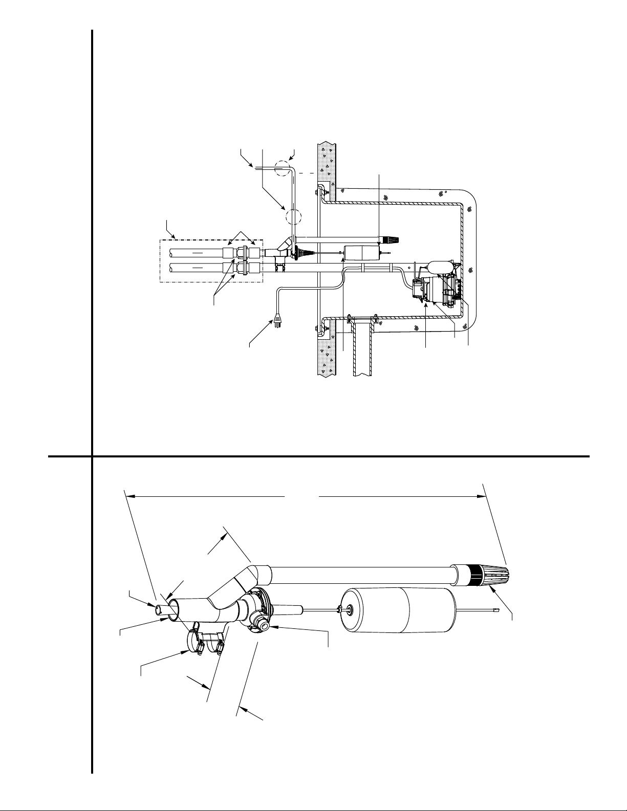
PUMP ON LEVEL
AND ABOVE PRIMARY
ABOVE SUCTION SCREEN
OFF LEVEL MUST BE
6" M N.
and Separate Discharge Pipe
CHECK VALVES
PLUG
3-PRONG
Typical Installation with Submersible Pump
38 3/4
HEIGHT
8 1/8
DISCHARGE
LENGTH
BY TESTING. SEE NSTRUCTIONS.
ON LEVEL TO BE DETERM NED
ON LEVEL
PRIMARY PUMP
FLOAT
ON/OFF
SUBMERSIBLE PUMP
Dimensions
1 1/2
SLIP FIT
HOSE CLAMPS FOR
PUMP DISCHARGE PIPE
ATTACHING TO PRIMARY
© Copyright 2013 Star Water Systems. All Rights Reserved.
5 1/2
WIDTH
SUCTION
3/4 NPT
WATER SUPPLY
5
Page 6
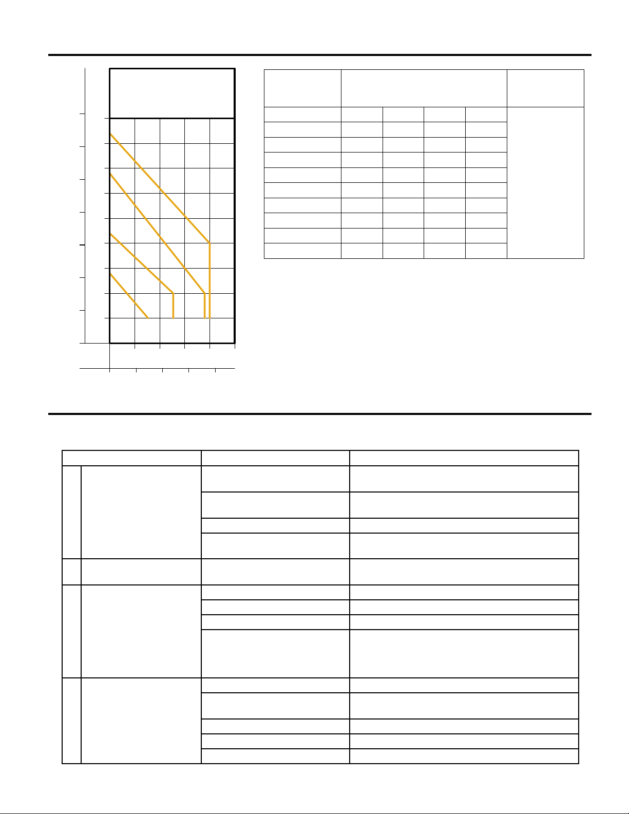
Performance Characteristics
FEET
METERS
14
45
40
12
35
10
30
8
25
TOTAL DYNAMIC HEAD
20
6
15
4
10
2
5
0
GALLONS
LITERS
0
PUMP PERFORMANCE
CURVE
MODEL S1503
80 PSI
60 PSI
40 PSI
20 PSI
5 10
20 40
FLOW PER MINUTE
15
20
8060
IL1080
Total Dynamic Head/Flow per
Minute
Model S1503
Dewatering Only UPC #
Feet 20 PSI 40 PSI 60 PSI 80 PSI
5 7. 7 12.7 19.0 20.0
10 3.4 12.7 19.0 20.0
15 - 7. 4 15.0 20.0
20 - 2.0 11. 1 20.0
25 - - 7. 1 15.3
054757076658
30 - - 3.2 10.9
35 - - - 6.4
40 - - - 1.8
Shut-off Head: 14.0 ft. 22.0 ft. 34.0 ft. 42.0 ft.
Pump capacity varies due to: Inlet Water Pressure, Working Water
Pressure, Discharge Elevation, Number of Pipe Fittings, Inlet and
Outlet Pipe Size, Fluid Viscosity, Degree of Water Clarity, Water
Temperature. The flow rates in the chart are approximate values.
25
NOTE: Some districts may require a reduced pressure principle
backflow preventer per ASSE Standards 1013. Check Local Codes.
Troubleshooting Guide
CONDITION POSSIBLE CAUSE REMEDY
PUMP WILL NOT START
A
OR RUN
PUMP STARTS TOO
B
SOON
PUMP WILL NOT SHUT
C
OFF
PUMP OPERATES BUT
D
DELIVERS LITTLE OR NO
WATER
Inadequate incoming water pressure.
Excessive water pressure. Install regulator and reduce pressure below 100 PSI
Debris around Intake. Clear debris from pit and foot valve strainer.
Float hung up on pit or primary
pump
Float "ON" point is adjusted too
low.
Float is obstructed. Inspect oat operation and correct problem.
Float "OFF" point is too low. Refer to STEP 2.
Foot Valve above water level. Adjust Float - Refer to STEP 2.
Internal valve diaphragm vent
hole is plugged with debris.
Debris around Intake. Clear debris from pit and foot valve strainer.
Inadequate incoming water pres-
sure.
Blockage in discharge pipe. Remove pipe and ush out debris.
Foot Valve above water level. Adjust Float - Refer to STEP 2.
Vertical lift too high. Change discharge piping or contact technical service.
Check incoming water line for closed valve, low water
pressure or clogged lter/strainer.
with valve closed.
Move pumps so that the oats move freely and do not
contact pit, piping or each other.
Refer to STEP 2.
Turn off water supply to pump and back on repeatedly
to dislodge debris. If this process does not remedy
the problem, service pump to clear debris or replace
valve assembly.
Check incoming water line for closed valve or low
water pressure.
© Copyright 2013 Star Water Systems. All Rights Reserved.
6
Page 7
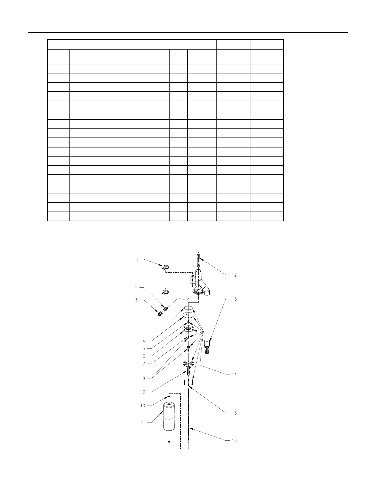
Illustrated Parts Breakdown
HOMEGUARD SERVICE PARTS - MODEL 1503 1503-A 1503-B
ITEM DESCRIPTION QTY NOTES
11/10 thru
05/11
1 Clamps 2 * 001766 001766
2 Backow valve assembly 1 018587 018587
3 Sharkbite tting 1 018584 018584
4 Diaphragm and O-ring 1 * 150553 150553
5 Plunger assembly 1 * 018589 018589
6 Nozzle seat 1 018557 151713
7 Spring 1 * 018564 018564
8 Float rod magnet guide assembly 1 150084 150084
9 Float rod guide 1 150741 150741
10 Float stop assembly 2 * 054085 054085
11 Float 1 018567 018567
12 Venturi 1 4C5532 4C5532
13 Foot valve 1 ** 150260 150260
14 Valve assemby 1 150101 150101
15 Screws 6 * 001885 001855
16 Float rod 1 018583 018583
* Rebuild kit 1 150554 150554
06/11 thru
Current
* Items included in rebuild kit.
** Foot valve will need to be cut off as close to top of valve as possible and new one glued in place.
© Copyright 2013 Star Water Systems. All Rights Reserved.
7
SK2741
Page 8

STAR
95 North Oak St. | Kendallville, IN 46755 | 800-345-9422
®
www.starwatersystems.com
© Copyright 2010 Star Water Systems. All rights reserved.
8
Page 9

AVISO AL INSTALADOR: Las instrucciones deben permanecer en el sitio donde se realice la instalación.
FW1379S 0212
La siguiente información sobre
este producto reeja las condiciones existentes en la fecha de
publicación. Se debe consultar a
la fábrica cualquier discrepancia o
inconsistencia que exista.
STAR
®
Visite nuestro sitio web:
starwatersystems.com
Supersedes
1010
HomeGuard®
OPTIMA
MODELO 1503
SISTEMA DE BOMBA DE SUMIDERO AUXILIAR
DE EMERGENCIA ACCIONADA POR AGUA
FABRICADO EN PVC
LISTA DE VERIFICACIÓN PARA LA PREINSTALACIÓN
1. Inspeccione la bomba. Los productos se dañan ocasionalmente durante el transporte. Si la unidad o cualquiera de sus componentes tiene daños,
comuníquese con su proveedor antes de utilizarla.
2. Lea todas las instrucciones de instalación y arranque. Consérvelas para referencia futura.
VER ABAJO LA LISTA DE ADVERTENCIAS
1. Protéjase; desconecte siempre el suministro de energía de la
fuente de alimentación antes de manipular los componentes de la
bomba primaria.
VER ABAJO LA LISTA DE PRECAUCIONES
1. Esta bomba ha sido diseñada para aguas claras. No la use en
tanques sépticos para bombear euentes o en fosos cloacales para
bombear aguas negras.
2. Todo trabajo de reparación y mantenimiento de su sistema auxiliar
debe ser realizado por un servicio de mantenimiento autorizado.
3. La instalación de esta bomba auxiliar requiere un interruptor de
otador de nivel variable para su funcionamiento. El instalador
debe asegurarse de que la bomba y las peculiaridades del foso
REFIÉRASE A LA GARANTÍA EN LA PÁGINA 2.
© 2013 Star Water Systems. Todos los derechos reservados.
no intereran con el interruptor de otador y de que este esté bien
instalado para que la bomba se encienda y apague. Se recomienda
que el foso tenga un diámetro de 46 cm (18 pulgadas) o más para
que quepan una bomba primaria y una bomba auxiliar.
4. Verique la instalación de los otadores de las bombas primaria y
auxiliar para asegurarse de que ambas se muevan libremente y no
haya obstáculos que intereran con su desplazamiento. Se debe
mantener una distancia apropiada entre los otadores.
5. La varilla de los otadores se debe alzar una vez al mes para activar
la bomba manualmente. Mantenga la bomba encendida durante por
lo menos 15 segundos para prevenir la acumulación de depósitos
de calcio y escombros que podrían dañarla.
La turbulencia causada por el agua que
entra a alta velocidad podría afectar negativamente la acción
de encendido y apagado del mecanismo del otador. Si ocurre
esta condición, se debe amortiguar el agua que entra para evitar
la turbulencia excesiva.
9
Page 10

Garantía limitada
La garantía de este producto expirará después de transcurrido el más
corto de los siguientes lapsos: un año contado a partir de la fecha de
compra o dos años contados a partir de la fecha de fabricación. Sujeto
a las condiciones establecidas a continuación, el fabricante reparará
o reemplazará al consumidor original cualquier porción del producto
identificada como defectuosa debido a materiales o mano de obra
defectuosos. Para obtener servicio en garantía, acuda al establecimiento
donde fue comprado el producto. El fabricante retiene el derecho y
discreción exclusivos para determinar si se debe reparar o reemplazar un
equipo, parte o componente defectuoso. Daños debidos a condiciones que
estén fuera del control del fabricante no están cubiertos por esta garantía.
ESTA GARANTÍA NO CUBRE: (a) defectos o disfunciones resultantes
de una instalación, operación o mantenimiento de la unidad de una forma
diferente a la establecida en las instrucciones impresas proporcionaadas;
(b) fallas producidas por abuso, accidente o negligencia, o por el uso de
productos químicos o aditivos inapropiados en el agua; (c) servicios de
mantenimiento normales así como las partes usadas en conexión con
tales servicios; (d) aquellas unidades que no hayan sido instaladas de
conformidad con los códigos, ordenanzas y buenas prácticas locales
aplicados normalmente en esta industria; y (e) unidades usadas para fines
diferentes a aquéllos para los que fueron diseñadas y fabricadas.
DEVOLUCIÓN DE COMPONENTES GARANTIZADOS: Todo ítem que
deba ser reparado o reemplazado de conformidad con esta garantía
deberá ser devuelto, porte pagado, a la dirección del fabricante en
Kendallville, Indiana, EE. UU. o al lugar que indique el fabricante.
LA GARANTÍA AQUÍ ESPECIFICADA REEMPLAZA TODAS LAS
DEMÁS GARANTÍAS EXPRESAS, Y NO PODRÁ SER EXTENDIDA
NI MODIFICADA POR NADIE. TODA GARANTÍA IMPLÍCITA ESTARÁ
LIMITADA AL PERÍODO DE LA GARANTÍA LIMITADA, MÁS
ALLÁ DEL CUAL DICHAS GARANTÍAS IMPLÍCITAS QUEDARÁN
ANULADAS Y EXCLUIDAS. BAJO NINGUNA CIRCUNSTANCIA
EL FABRICANTE PODRÁ SER RESPONSABILIZADO DE DAÑOS
INCIDENTALES, INDIRECTOS O ESPECIALES TALES COMO,
AUNQUE NO TAXATIVAMENTE, PÉRDIDA DE OTRA PROPIEDAD
O EQUIPO, LUCRO CESANTE, INCOMODIDADES U OTROS
DAÑOS INCIDENTALES O INDIRECTOS DE CUALQUIER TIPO O
NATURALEZA. LA RESPONSABILIDAD DEL FABRICANTE NO
PODRÁ EXCEDER EL PRECIO DEL PRODUCTO SOBRE EL CUAL
ESTÁ BASADA DICHA RESPONSABILIDAD.
Esta garantía le otorga derechos legales específicos, y usted podría tener
también otros derechos que varían de un estado a otro. Algunos estados
no permiten limitaciones en la duración de las garantías implícitas o la
exclusión de daños incidentales o indirectos, en cuyo caso las limitaciones
antes mencionadas podrían no ser aplicables a su caso.
GARANTÍA VÁLIDA EN CANADÁ Y MÉXICO.
Recomendaciones prácticas para facilitar la instalación
1. Retire los escombros que haya en el foso antes de
realizar la instalación.
2. Asegúrese de que la bomba esté rmemente instalada
en la tubería de descarga de la bomba principal y de
que las dos bombas no intereran entre sí.
3. Instale una válvula de retención a la que se le pueda
hacer mantenimiento en la línea de descarga.
4. Instale un ltro o un colador en la línea de suministro
de agua, antes de la bomba. El tamaño del ltro o
colador debe ser apropiado a n de minimizar la caída
Lo que DEBE y NO DEBE hacer para instalar una unidad
1. LEA completamente todo el material sobre la
instalación provisto con la bomba.
2. INSPECCIONE la unidad para determinar si hay algún
daño visible causado durante el envío. Comuníquese
con el proveedor si la bomba está dañada.
3. RETIRE todos los escombros del foso antes de
realizar la instalación.
4. INSTALE una válvula de retención de unión (ver el
PASO 3) en la línea de descarga. NO use una tubería
de descarga de menor tamaño que la descarga
recomendada para la bomba.
5. INSTALE un ltro o colador en la línea de suministro
de agua, antes de la bomba, para evitar que partículas
pequeñas obstruyan el funcionamiento de la válvula.
6. PRUEBE la bomba inmediatamente después de
realizar la instalación para asegurarse de que el
sistema funcione correctamente.
© 2013 Star Water Systems. Todos los derechos reservados.
10
de presión y retener al mismo tiempo las partículas
que tengan un diámetro mínimo de 0,5 mm (0,020
pulgadas).
5. Verique la unidad inmediatamente después de
instalarla. Reérase al PASO 5.
6. Verique los niveles de encendido y apagado del
otador conforme a las instrucciones del PASO 2.
7. Obtenga el número de modelo, el código de fecha y
las instrucciones de instalación antes de llamar a la
fábrica.
7. EXAMINE todos los códigos nacionales y locales
pertinentes y verique que la instalación se realice
conforme a cada uno de ellos.
8. NO use la bomba Home Guard® Optima en agua
caliente. NO use la bomba Home Guard® Optima para
eliminar aguas residuales, aguas negras, euentes o
agua que contenga escombros.
9. NO use una manguera de jardín. Las mangueras de
jardín no están diseñadas para soportar la presión de
los sistemas de suministro de agua públicos y podrían
crear fugas o reventarse, causando inundaciones. La
bomba Home Guard® Optima requiere un sistema de
tuberías permanentes fabricado con componentes de
cobre, PEX o CPVC.
Page 11

Instalación
La bomba Home Guard® Optima se puede instalar muy fácilmente como una bomba de relevo para una bomba eléctrica de
sumidero (ver las ilustraciones). Sin embargo, se debe instalar una válvula de retención entre la bomba eléctrica y la bomba
Home Guard® Optima.
Nota 1: Según el Código Uniforme de Plomería (Uniform Plumbing Code) y los códigos de plomería de algunos estados, la
instalación de este producto requiere el uso de un dispositivo de prevención de contraujo RPZ (Reduced Pressure Zone - Zona
de presión reducida). Comuníquese con su entidad local de reglamentación de aguas públicas para obtener más información
sobre los requisitos en su área especíca.
Nota 2: Según el Código Uniforme de Plomería y la norma IAPMO PS119, la descarga de la bomba de sumidero accionada por
agua no se debe conectar a la descarga de la bomba de sumidero primaria.
PASO 1: Colocación de la bomba en el foso
Nota: Si el foso tiene una tapa, hay que modicarla para acomodar la bomba Home Guard® Optima.
1.1) Inspeccione el pozo para asegurarse de que no tenga escombros y límpielo si es necesario.
1.2) Coloque la bomba en el foso, asegurándose de que la conexión de entrada de la bomba esté por lo menos a 15 cm (6
pulgadas) por encima del piso del sótano o del borde superior del foso. Asegúrese de que la bomba esté rmemente
instalada en la tubería de descarga de la bomba primaria. Marque la posición en la tubería de descarga.
IMPORTANTE Esta bomba se debe utilizar como auxiliar de la bomba primaria. Asegúrese de que no haya interferencias entre
las dos bombas, especialmente entre los sistemas de otadores.
PASO 2: Ajuste de los topes del otador
2.1) Después de colocar la bomba Home Guard® Optima en el foso, mida la posición de encendido deseada (la posición debe
estar algunos centímetros por encima del nivel de encendido de la bomba existente). La bomba se enciende cuando el
nivel de agua cae de 5 a 8 cm (2 a 3 pulgadas) por debajo del tope superior del otador, conforme a la presión del agua de
entrada. Calcule la posición apropiada del tope del otador de acuerdo a esta distancia.
2.2) El nivel de apagado se determina en base a la otación del otador, así como a la presión del agua de entrada,
aproximadamente de 15 a 20 cm (6 a 8 pulgadas) por debajo del nivel de encendido. El nivel de apagado debe estar por
encima de la rejilla de succión de la válvula de aspiración. El nivel de apagado de la bomba no cambia cuando se ajusta el
tope inferior del otador. Se recomienda apretar bien el tope inferior en la parte inferior del otador para que no se deslice
sobre la varilla.
2.3) Saque la bomba del foso y ajuste los topes del otador según sea necesario. Apriete todas las tuercas. Asegúrese de
apretar bien el tope inferior para que no se desprenda. Si el tope inferior se desprende, el otador se caerá de la varilla, la
bomba dejará de funcionar y se podría averiar.
2.4) Vuelva a colocar la bomba en el foso, en la misma posición sobre la tubería de descarga de la bomba primaria, tal como se
marcó previamente (Paso 1.2). Esto asegurará que los niveles de encendido y apagado sean consistentes con los cálculos
realizados.
PASO 3: Instalación de la tubería de descarga
3.1) Fije la tubería de descarga a la bomba con pegamento, tal como muestra la ilustración de abajo (referencia SK2721B).
3.2) Según el Código Uniforme de Plomería y la norma IAPMO PS119, la descarga de la bomba de sumidero accionada por
agua no se debe conectar a la descarga de la bomba de sumidero primaria.
3.3) Se debe instalar una válvula de retención en la línea de descarga para que la instalación funcione correctamente. Se
recomienda utilizar las siguientes válvulas de retención Star Water Systems: KH34 o KH81. Algunos códigos locales
estipulan una válvula de retención de unión con un otador.
PASO 4: Instalación de la tubería de suministro de agua
4.1) Cierre el suministro de aguas públicas y conecte la tubería del sistema a la línea de aguas públicas. Esta línea debe
derivarse de una línea de ¾ de pulgada y conectarse a la bomba Home Guard® Optima mediante una tubería de ¾
de pulgada. No use una manguera de jardín o alguna otra tubería exible. Instale una válvula de cierre en la línea de
suministro de ¾ de pulgada a la bomba Home Guard® Optima. Use el método de prevención de contraujo que se requiera
en su localidad.
© 2013 Star Water Systems. Todos los derechos reservados.
11
Page 12

Instalación (continuación)
PASO 4: (continuación)
4.2) No suelde las conexiones de bronce a menos de 18 pulgadas de la bomba Home Guard® Optima, ya que el calor de la
antorcha dañará la cubierta exterior.
4.3) Cuando instale conexiones roscadas en la entrada de la bomba Home Guard® Optima, no aplique una solución
impermeabilizante en las roscas; use cinta aislante PTFE (Teon®). Tenga especial cuidado de evitar que queden escombros
(incluyendo trozos de cinta aislante) dentro de la conexión de entrada y que puedan obstruir la válvula.
4.4) La bomba Home Guard® Optima incluye una conexión de presión instalada en campo, diseñada para crear uniones con
tubos de cobre, PEX, CPVC de ¾ de pulgada. La conexión se debe instalar en la rosca NPT de ¾ de pulgada, en la
conexión de entrada de la bomba. Durante la instalación se debe tener cuidado de no sobreapretar la conexión en la entrada
de la bomba, ya que se podría romper la cubierta. Sujete la conexión de entrada con una llave auxiliar mientras aprieta
la conexión de presión. Si no utiliza la conexión de presión, debe observar las mismas precauciones que se siguen para
realizar cualquier instalación en la conexión de entrada.
4.5) Purgue la línea de agua antes de conectar la bomba Home Guard® Optima, para evitar la entrada de escombros que
podrían obstruir la válvula.
4.6) Si usa una conexión de presión, corte los extremos del tubo en ángulo recto. Asegúrese de que el extremo cortado no
tenga rebabas ni daños. Después de limpiar el extremo cortado en ángulo recto, dibuje una marca de profundidad en la
pared exterior de la tubería a 2,5 cm (1 pulgada) del extremo. Inserte el tubo a través del collar de desprendimiento hasta
que descanse contra el anillo de sujeción. Empuje rmemente el tubo mientras lo gira ligeramente hasta que se detenga
contra el tope. La marca de profundidad debe observarse en el extremo del collar de desprendimiento. No se requiere un
revestimiento si se utiliza una tubería de CPVC o cobre, y se puede retirar si lo permiten los códigos locales. El revestimiento
de la tubería se puede retirar fácilmente con un alicate de puntas largas.
4.7) Después de instalar la bomba y de conectar el suministro de aguas públicas, abra las llaves de suministro de aguas públicas
y de la línea de suministro de agua. Inspeccione el cuerpo de la válvula y todas las conexiones para asegurarse de que no
haya fugas. Cierre el suministro de aguas públicas y arregle cualquier fuga que haya antes de encender la bomba.
PASO 5: Vericación del funcionamiento de la bomba
5.1) Desenchufe la bomba primaria para que no se encienda.
5.2) Llene el foso de agua hasta que la bomba Home Guard® Optima se encienda.
5.3) Asegúrese de que la bomba se encienda y apague en las posiciones programadas.
5.4) Asegúrese de que no haya fugas en la línea de descarga.
5.5) Si hace falta algún ajuste, suba o baje los topes conforme a las instrucciones del PASO 2.
5.6) Si la bomba no funciona correctamente después de realizar los pasos anteriores, consulte la “Guía de detección y resolución
de problemas”.
5.7) Cuando concluya las pruebas, vuelva a enchufar la bomba primaria a una fuente de corriente alterna.
PRESIÓN DEL AGUA:
20 PSI, presión mínima con la válvula abierta.
80 PSI, presión máxima con la válvula abierta.
100 PSI, presión máxima con la válvula cerrada.
EFICIENCIA:
La capacidad de la bomba aumentará conforme a la presión y el caudal del agua doméstica.
Si se tiene una carga estática de 2,4 metros (8 pies) con una presión de ujo de 20 PSI en la tubería de suministro, se requiere
un caudal de entrada de 3,8 litros (1 galón) para extraer la misma cantidad de agua del foso. A medida que aumente la presión
del suministro de agua, con una carga estática constante, disminuirá la cantidad de agua requerida.
© 2013 Star Water Systems. Todos los derechos reservados.
12
Page 13

CANALISATION
A
D’AMENÉE D’EAU
DISPOSITIF DE
PRÉVENTION DE
RETOUR D’EAU ET
FILTRE (FOURNIS
SK2721B
PAR DES TIERS)
MINI 15,2 CM (6 PO)
TUYAUTERIE (FOURNIE
PAR DES TIERS)
RACCORDS
de descarga separada
CLAPETS DE
NON-RETOUR
FICHE À TROIS
BROCHES
Instalación típica con bomba sumergible y tubería
NIVEAU DE DÉMARRAGE
À DÉTERMINER PAR
UN ESSAI. VOIR LES
DIRECTIVES.
LE NIVEAU D’ARRÊT DOIT SE
TROUVER AU-DESSUS DE LA
CRÉPINE D’ASPIRATION ET DU
POMPE PRIMAIRE
NIVEAU DE DÉMARRAGE DE L
NIVEAU DE
DÉMARRAGE DE LA
FLOTTEUR
MARCHE-ARRÊT
POMPE PRIMAIRE
POMPE SUBMERSIBLE
Dimensiones
CONEXIÓN
DESLIZANTE
DESCARGA
DE 1-1/2
PULGADAS
ABRAZADERAS DE
MANGUERA PARA
CONECTAR LA UNIDAD A
LA TUBERÍA DE DESCARGA
© 2013 Star Water Systems. Todos los derechos reservados.
20,6 CM
(8-1/8 PULG.)
LONGITUD
DE LA BOMBA PR MARIA
14 CM
(5-1/2 PULG.)
ANCHURA
98,4 CM (38-3/4
PULG.) ALTURA
13
SUMINISTRO DE AGUA DE
SUCCIÓN
3/4 DE PULG. NPT
Page 14

Características de rendimiento
14
12
10
8
CARGA DINÁMICA TOTAL
6
4
2
0
PIES
METROS
45
40
35
30
25
20
15
10
5
GALONES
LITROS
REND MIENTO DE LA BOMBA
0
CURVA DE
MODELO S1503
40 PSI
20 PSI
5 10
20 40
CAUDAL POR MINUTO
60 PSI
15
20
CARGA/CAUDAL DINÁMICO TOTAL
POR MINUTO
ACHIQUE SOLAMENTE
S1503
LITROS
GALONES
10,4 m (34,0 pies)
LITROS
GALONES
12,8 m (42,0 pies)
80 PSI
MODELO
PIES
METROS
Altura de interrupción
018586
GALONES
4,3 m (14,0 pies)
LITROS
GALONES
6,7 m (22,0 pies)
La capacidad de la bomba varía debido a: presión de entrada del agua, presión de trabajo
del agua, altura de la descarga, número de conexiones de tubería, tamaño de las tuberías
de entrada y salida, viscosidad del uido, nivel de claridad del agua, temperatura del agua.
Los valores de los caudales en el cuadro son aproximados.
NOTA: Algunas municipalidades podrían requerir un limitador de contraujo principal para
25
reducir la presión, conforme a las normas ASSE 1013. Consulte los códigos locales.
8060
IL1094
LITROS
Guía de detección y resolución de problemas
CONDICIÓN POSIBLE CAUSA SOLUCIÓN
LA BOMBA NO ARRANCA O
NO FUNCIONA
LA BOMBA SE ENCIENDE
DEMASIADO PRONTO
LA BOMBA NO SE APAGA
LA BOMBA FUNCIONA PERO
BOMBEA POCA AGUA O NO
BOMBEA AGUA
Inadecuada presión de entrada del
agua.
Presión de agua excesiva.
Escombros junto a la entrada de
agua.
Flotador atascado en el foso o en la
bomba primaria.
El punto de encendido del otador
está demasiado bajo.
El otador está obstruido. Inspeccione el funcionamiento del otador y corrija el problema.
El punto de apagado del otador está
demasiado bajo.
La válvula de aspiración está encima
del nivel de agua.
El oricio de ventilación de la válvula
de diafragma interna está obstruido
con escombros.
Escombros junto a la entrada de
agua.
Inadecuada presión de entrada del
agua.
La tubería de descarga está ob-
struida.
La válvula de aspiración está encima
del nivel de agua.
La descarga vertical es demasiado
alta.
Revise la línea de entrada de agua para determinar si la válvula está
cerrada, la presión de agua es baja o el ltro/colador está obstruido.
Instale un regulador y reduzca la presión a menos de 100 PSI con la
válvula cerrada.
Limpie los escombros del foso y el colador de la válvula de aspiración.
Mueva las bombas de forma que los otadores se desplacen l bre-
mente sin tocarse entre sí, ni tocar el foso o las tuberías.
Reérase al PASO 2.
Reérase al PASO 2.
Ajuste el otador - Reérase al PASO 2.
Cierre y abra repetidamente el suministro de agua a la bomba para
desprender los escombros. Si este proceso no soluciona el problema, hágale un mantenimiento a la bomba para eliminar los escombros o cambie el ensamblaje de la válvula.
Limpie los escombros del foso y el colador de la válvula de aspiración.
Revise la línea de entrada de agua para determinar si la llave está
cerrada o hay poca presión de agua.
Retire la tubería y elimine los escombros.
Ajuste el otador - Reérase al PASO 2.
Cambie la tubería de descarga o solicite asistencia técnica.
© 2013 Star Water Systems. Todos los derechos reservados.
14
Page 15

Desglose de los componentes en la ilustración
REPUESTOS DE HOMEGUARD - MODELO 1503 1503-A
ÍTEM DESCRIPCIÓN CANT. NOTAS
1 Abrazadera 2 * 001766 001766
2 Conjunto de la válvula de contraujo 1 018587 018587
3 Conector de presión (sharkbite) 1 018584 018584
4 Diafragma y junta tórica 1 * 150553 150553
5 Conjunto del émbolo 1 * 018589 018589
6 Base de la tobera 1 018557 151713
7 Resorte 1 * 018564 018564
8 Conjunto de la guía imantada de la varilla del otador 1 150084 150084
9 Guía de la varilla del otador 1 150741 150741
10 Conjunto del tope del otador 2 * 054085 054085
11 Flotador 1 018567 018567
12 Venturi 1 4C5532 4C5532
13 Válvula de aspiración 1 ** 150260 150260
14 Conjunto de la válvula 1 150101 150101
15 Tornillo 6 * 001885 001855
16 Varilla del otador 1 018583 018583
* Juego de reposición 1 150554 150554
11.10
hasta
05.11
Del
06.11 a la
fecha
* Ítems incluidos en el juego de reposición.
** La válvula de aspiración se debe cortar lo más cerca posible de la parte superior y la válvula nueva se debe
jar con pegamento.
© 2013 Star Water Systems. Todos los derechos reservados.
15
SK2741
Page 16

STAR
95 North Oak St. | Kendallville, IN 46755 | 800-345-9422
®
www.starwatersystems.com
© 2013 Star Water Systems. Todos los derechos reservados.
16
Page 17

AVIS À L’INSTALLATEUR : laisser la notice d’installation avec l’équipement.
L’informa ion sur l’équipement
contenue dans la présente reète
les conditions au moment de la
publication. Prendre contact avec
l’usine en cas de différences ou
d’incohérences.
STAR
®
HomeGuard®
OPTIMA
Modèle S1503
FW1379F 0212
Supersedes
1010
visitez notre site Web:
starwatersystems.com
POMPE D’ASSÈCHEMENT DE SECOURS
À ENTRAÎNEMENT PAR EAU
EN PCV
LISTE DE CONTRÔLE AVANT L’INSTALLATION
1. Inspecter la pompe. Il arrive que des pièces soient endommagées pendant l’expédition. Si la pompe ou l’une de ses pièces est endommagée,
prendre contact avec le distributeur avant de la mise en service.
2. Lire toutes les directives concernant l’installation et le démarrage. Garder la notice pour consultation future.
pompage ou aux parties saillantes de la fosse et est xé de manière
VOIR LA LISTE DES AVERTISSEMENTS CI-DESSOUS
1. Par souci de protection, toujours déconnecter
l’alimentation électrique de sa source avant de manipuler
les composantes de la pompe primaire.
VOIR LA LISTE DES MISES EN GARDE CI-DESSOUS
1. La pompe est conçue pour pomper de l’eau limpide. Ne pas l’utiliser
pour pomper l’efuent d’une fosse septique ni pour pomper les eaux
d’égout.
2. La pompe de secours doit être réparée et entretenue par un centre
de service agréé.
3. La pompe de secours requiert l’installation d’un interrupteur à otteur
détecteur de niveau pour pouvoir fonctionner. L’installateur est tenu
de veiller à ce que l’interrupteur ne s’accroche pas à l’équipement de
à permettre le démarrage et l’arrêt de la pompe. On recommande
que la fosse ait un diamètre d’au moins 45,7 cm (18 po) pour pouvoir
y loger aussi bien la pompe primaire que la pompe de réserve.
4. Vérier le placement des otteurs des pompes primaire et de réserve
pour assurer qu’ils se déplacent librement et ne rencontrent aucune
obstruction qui pourrait empêcher leurs mouvements. Il faut maintenir
sufsamment d’espace entre les otteurs.
5. Activer la pompe manuellement une fois par mois en soulevant la
tige du otteur. Laisser la pompe fonctionner pendant au moins 15
secondes pour l’empêcher d’accumuler des dépôts de calcaire et
des débris qui risquent de l’endommager.
d’au à haute vitesse risque de nuire à l’action marche-arrêt
du mécanisme du otteur. Si c’est le cas, il faut installer des
déecteurs pour éviter une turbulence excessive.
La turbulence causée par l’admission
SE REPORTER À LA GARANTIE À LA PAGE 2
© 2013 Star Water Systems. Tous droits réservés.
17
Page 18

Garantie limitée
Ce produit est garanti pendant la période expirant la première, un
an après la date d'achat ou deux ans après la date de fabrication.
Selon les conditions établies ci-après, le fabricant réparera ou
remplacera pour le client d'origine, toute partie du produit qui s'est
avérée défectueuse à cause d'un défaut de matériau ou de maind'œuvre. Pour obtenir un service sous garantie, communiquer avec
le détaillant qui a vendu le produit. Le fabricant se réserve le droit et
le choix de déterminer s'il remplacera ou réparera l'équipement, les
pièces ou les composants défectueux. Les dommages résultant de
conditions hors du contrôle du fabricant ne sont pas couverts par
cette garantie.
CETTE GARANTIE NE S'APPLIQUE PAS : (a) Aux défauts
ou mauvais fonctionnements résultant d'une installation, d'une
utilisation ou d'un entretien incorrects de l'unité conformément
aux instructions imprimées fournies; (b) Aux pannes résultant
d'un abus, d'un accident ou d'une négligence ou de l'utilisation
d'additifs ou de produits chimiques inappropriés dans l'eau; (c) Aux
services d'entretien normaux et aux pièces utilisées dans le cadre
de cet entretien; (d) Aux unités qui n'ont pas été installées selon la
réglementation locale et les règles de l'art; et (e) L'unité est utilisée
pour des fins autres que celles pour lesquelles elle a été conçue et
fabriquée.
RETOUR DES COMPOSANTS SOUS GARANTIE : Tout article à
être réparé ou remplacé selon les termes de la présente garantie
doit être retourné au fabricant, à Kendalville, Indiana, USA ou à tout
autre endroit désigné par le fabricant, port payé.
LA PRÉSENTE GARANTIE REMPLACE TOUTE AUTRE
GARANTIE EXPRESSE ET NE PEUT PAS ÊTRE PROLONGÉE
OU MODIFIÉE PAR QUICONQUE. TOUTE GARANTIE
IMPLICITE DOIT ÊTRE LIMITÉE À LA PÉRIODE DE LA
GARANTIE LIMITÉE, ET PAR LA SUITE, TOUTE GARANTIE
IMPLICITE SERA REFUSÉE ET EXCLUE. LE FABRICANT NE
DEVRA, EN AUCUNS CAS, ÊTRE TENU RESPONSABLE DE
TOUS DOMMAGES-INTÉRÊTS ACCESSOIRES, INDIRECTS
OU SPÉCIAUX, TELS QUE, MAIS SANS S'Y LIMITER, LES
DOMMAGES OU LA PERTE DE PROPRIÉTÉ OU ÉQUIPEMENT,
PERTES DE REVENUS, INCONVÉNIENTS, OU AUTRES
DOMMAGES-INTÉRÊTS ACCESSOIRES OU INDIRECTS DE
QUELQUE NATURE. LA RESPONSABILITÉ DU FABRICANT
NE DOIT PAS DÉPASSER LE PRIX DU PRODUIT SUR LEQUEL
UNE TELLE RESPONSABILITÉ EST BASÉE.
Cette garantie confère à l'acheteur des droits précis et celui-ci
peut en avoir d'autres selon le lieu. Certains états ou provinces
ne permettent pas de limiter la durée des garanties implicites ou
l'exclusion des dommages-intérêts accessoires ou indirects, auquel
cas les limitations ci-dessus ne s'appliquent pas.
GARANTIE VALIDE AU CANADA ET AU MEXIQUE.
Conseils utiles pour faciliter l’installation
1. Enlever tous les détritus de la fosse avant
l’installation.
2. Vérier que la pompe est solidement xée à la conduite
de refoulement de la pompe primaire et que les deux
pompes ne se gênent pas mutuellement.
3. Monter un clapet de non-retour pouvant être entretenu
dans la conduite de refoulement.
4. Installer un ltre ou une crépine dans le tuyau
d’alimentation d’eau en aval de la pompe. Choisir un
ltre ou une crépine de dimensions correctes, pour
Conseils pour l’installation de la pompe
1. LIRE toute la documentation fournie avec la pompe.
2. INSPECTER la pompe pour détecter les traces visibles
de dommages causés au cours de l’expédition.
Prendre contact avec le fabricant si l’appareil semble
endommagé.
3. ENLEVER tous les détritus de la fosse avant
l’installation.
4. MONTER un clapet de non-retour à raccord union
(voir ÉTAPE 3) dans la conduite de refoulement. NE
PAS utiliser une conduite de refoulement de diamètre
inférieur à celui qui est recommandé.
5. INSTALLER un ltre ou une crépine dans le tuyau
d’alimentation d’eau en amont de la pompe pour
empêcher les petites particules de bloquer la vanne
de commande.
minimiser la chute de pression tout en piégeant les
particules d’un diamètre minimal de 0,5 mm (0,020
po).
5. Essayer l’appareil immédiatement après son
installation. Se reporter à l’ÉTAPE 5.
6. Contrôler les niveaux marche-arrêt du otteur suivant
les directives de l’ÉTAPE 2.
7. Avoir sous la main le numéro de modèle, le code
date et la notice d’installation à portée de main avant
d’appeler l’usine.
6. ESSAYER la pompe immédiatement après l’installation
pour vérier que le système fonctionne correctement.
7. ÉTUDIER tous les codes régionaux et nationaux
applicables et vérier que l’installation est conforme à
chacun d’entre eux.
8. NE PAS utiliser la pompe Home Guard® Optima dans
de l’eau chaude. NE PAS utiliser la pompe Home
Guard® Optima pour éliminer les eaux usées, eaux
d’égout, efuents ou eaux contenant des détritus.
9. NE PAS utiliser un tuyau d’arrosage. Un tuyau de ce
type n’est pas conçu pour supporter indéniment la
pression des eaux municipales et risque d’éclater,
provoquant une inondation. La pompe Home Guard®
Optima nécessite une tuyauterie permanente
fabriquée en cuivre, polyéthylène réticulé PEX ou
chlorure de polyvinyle chloré (PVC-C).
© 2013 Star Water Systems. Tous droits réservés.
18
Page 19

Installation
La pompe Home Guard® Optima peut être installée très facilement pour servir de pompe de secours d’une pompe
de puisard électrique (voir illustrations). Il faut cependant monter un clapet de non-retour entre la pompe électrique
et la pompe Home Guard® Optima.
Remarque 1 : Le code Uniform Plumbing Code (UPC – code régissant la plomberie) et les codes de certains États
régissant la plomberie exigent l’utilisation d’un dispositif RPZ (reduced pressure zone – zone de pression réduite) de
protection contre le retour d’eau. Faire appel à un plombier ou à la société de distribution des eaux pour obtenir plus
d’information concernant les exigences spéciques locales.
Remarque 2 : Les codes UPC et IAPMO PS119 interdisent le raccord du tuyau de refoulement de la pompe de
puisard hydraulique au tuyau de refoulement de la pompe de puisard primaire.
ÉTAPE 1 : Placement de la pompe dans la fosse
Remarque. - Si la fosse est munie d’un couvercle, il faut le modier pour l’adapter à la présence de la pompe Home
Guard® Optima.
1.1) Inspecter la fosse pour détecter la présence de détritus et la nettoyer, le cas échéant.
1.2) Placer la pompe dans la fosse en s’assurant que le raccord d’entrée de la pompe se trouve au moins à 15
cm (6 po) au-dessus du sol du sous-sol ou du rebord supérieur de la fosse du puisard. Vérier que la pompe
est solidement xée au tuyau de refoulement de la pompe primaire. Marquer l’emplacement sur le tuyau de
refoulement.
La pompe doit être utilisée comme pompe de secours de la pompe primaire. Veiller à ce qu’il n’y ait pas
d’interférence entre les deux pompes et surtout entre les dispositifs de otteur.
ÉTAPE 2 : Réglage de la butée du otteur
2.1) Après avoir installé la pompe Home Guard® Optima dans la fosse, mesurer le niveau de démarrage souhaité
du otteur (idéalement, quelques centimètres au-dessus du niveau de démarrage de la pompe existante). La
pompe se met en marche lorsque le niveau d’eau se trouve à environ 5 à 7,5 cm (2 à 3 po) en dessous de la
butée supérieure du otteur, suivant la pression du ux d’eau entrant. Calculer l’emplacement approprié de la
butée du otteur en fonction de cette distance.
2.2) La poussée hydrostatique du otteur et la pression d’eau du ux entrant déterminent le niveau d’arrêt de la
pompe, qui se trouve à environ 15 à 20 cm (6 à 8 po) en dessous du niveau de démarrage. Le niveau d’arrêt doit
se trouver au-dessus de la crépine d’aspiration du clapet de pied. L’ajustement de la butée inférieure ne modie
pas le niveau d’arrêt de la pompe. On recommande de bien serrer la butée inférieure contre le bas du otteur
pour l’empêcher de se déplacer le long de la tige du otteur.
2.3) Enlever la pompe de la fosse et ajuster les butées du otteur selon le besoin. Serrer toutes les vis. Veiller à
correctement serrer la butée inférieure pour qu’elle ne se détache pas. Si la butée inférieure se détache, le
otteur tombera de la tige, mettant la pompe hors service et risquant d’endommager la pompe.
2.4) Réinstaller la pompe dans la fosse au même endroit sur le tuyau de refoulement de la pompe primaire, tel
indiqué précédemment (étape 1.2). Ceci assure que les niveaux de démarrage et d’arrêt correspondent aux
calculs.
ÉTAPE 3 : Installation de la tuyauterie de refoulement
3.1) Coller le tuyau de refoulement dans la pompe, tel indiqué sur l’illustration suivante (no de référence SK2721B).
3.2) Les codes UPC et IAPMO PS119 interdisent le raccord du tuyau de refoulement de la pompe de secours à
entraînement par eau au tuyau de refoulement de la pompe de puisard primaire.
3.3) Il faut monter un clapet de non-retour sur le tuyau de refoulement pour assurer le fonctionnement correct de la
tuyauterie. On recommande les clapets de non-retour Star Water Systems suivants : KH34 et KH81. Certains
codes locaux exigent l’utilisation d’un raccord union à clapet à bille.
© 2013 Star Water Systems. Tous droits réservés.
19
Page 20

Installation (suite)
ÉTAPE 4 : Installation de la tuyauterie à la source d’eau
4.1) Couper l’alimentation d’eau municipale et raccorder la tuyauterie à la canalisation d’amenée d’eau municipale.
Elle doit être branchée sur un tuyau de ¾ po et raccordée à la pompe Home Guard® Optima en utilisant un tube
de ¾ po. Ne pas utiliser un tuyau d’arrosage ou autre tuyau ou tube exible. Monter un robinet d’arrêt dans le
tuyau de ¾ po alimentant la pompe Home Guard® Optima. Utiliser le dispositif de prévention de retour d’eau
approuvé par la juridiction locale.
4.2) Ne pas braser ni souder un raccord en cuivre à moins de 46 cm (18 po) de la pompe Home Guard® Optima, car
la chaleur émanant du chalumeau endommagera le corps de pompe.
4.3) En cas de xation d’un raccord leté à l’orice d’entrée d’eau de la pompe Home Guard® Optima, utiliser du
ruban d’étanchéité PTFE (Teon®) plutôt que de la pâte à joint. Faire très attention d’empêcher des détritus de
tous types (y compris des morceaux de ruban) de pénétrer dans l’orice d’entrée, entraînant le risque de rester
coincés dans la vanne de commande.
4.4) La pompe Home Guard® Optima est munie d’un raccord Push-to-Connect monté sur le terrain. Ce raccord est
conçu pour usage avec un tube de ¾ po en PEX, PVC-C ou cuivre. Il faut le monter sur le let NPT ¾ po du
raccord de l’orice d’entrée de la pompe. Lors de l’installation du raccord, il faut prendre garde de ne pas trop
serrer le raccord de l’orice d’entrée an de ne pas ssurer le corps de pompe. À l’aide d’une clé de dévissage,
maintenir le raccord de l’orice d’entrée pendant le serrage du raccord Push-to-Connect. Si l’on n’utilise pas le
raccord Push-to-Connect, il faut user des mêmes précautions lors du montage d’un quelconque autre raccord
sur le raccord de l’orice d’entrée.
4.5) Purger la canalisation d’eau avant de la raccorder à la pompe Home Guard® Optima, pour empêcher des détritus
éventuels de pénétrer dans la pompe et de boucher la vanne de commande.
4.6) En cas d’utilisation du raccord Push-to-Connect, couper les extrémités du tube perpendiculairement à l’axe du
tube. Vérier que l’extrémité coupée ne présente pas de bavures et n’est pas endommagée. Lorsque l’extrémité
du tube est perpendiculaire à l’axe et propre, placer un repère de profondeur à l’extérieur du tube à 2,5 cm (1
po) de l’extrémité. Glisser le tube au travers du collier de dégagement jusqu’à ce qu’il repose contre l’anneau
de prise. Appuyer fortement sur le tube en le tournant légèrement jusqu’à ce qu’il atteigne la butée de tube. Le
repère de profondeur doit se trouver au niveau de l’extrémité du collier de dégagement. Le revêtement de tube
n’est pas nécessaire en cas d’utilisation de tube en PVC-C ou cuivre et peut être enlevé selon les préférences
ou le code local. Le revêtement se retire facilement en utilisant une pince à bec pointu.
4.7) Après l’installation de la pompe et le raccord à la source d’eau municipale, ouvrir le robinet d’arrivée d’eau
municipale et le robinet de la canalisation d’admission d’eau. Vérier le corps de robinet et tous les raccords pour
détecter une fuite éventuelle. Fermer le robinet d’arrivée d’eau municipale et réparer les fuites éventuelles avant
de mettre la pompe en marche.
ÉTAPE 5 : Mise à l’essai du fonctionnement de la pompe
5.1) Débrancher la pompe primaire pour empêcher son démarrage.
5.2) Remplir le puisard d’eau jusqu’au démarrage de la pompe Home Guard® Optima.
5.3) Contrôler que la pompe démarre et s’arrête aux points ON/OFF souhaités.
5.4) Contrôler que la conduite d’évacuation ne fuit pas.
5.5) Si un réglage s’avère nécessaire, hausser ou baisser les butées du otteur conformément à l’ÉTAPE 2.
5.6) Si la pompe ne fonctionne pas correctement après l’exécution des étapes précédentes, se reporter au Guide de
dépannage.
5.7) Après avoir terminé l’essai, rebrancher la pompe primaire sur la prise c.a.
PRESSION D’EAU
Minimum 20 PSI lorsque la vanne est ouverte
Maximum 80 PSI lorsque la vanne est ouverte
Maximum 100 PSI lorsque la vanne est fermée
RENDEMENT
La capacité de pompage augmente avec la pression d’eau municipale et le débit.
Avec une charge statique de 2,4 m (8 pi) et une pression d’alimentation de 20 PSI à l’orice d’alimentation en eau
et avec l’eau coulant, 1 litre d’eau d’alimentation est requis pour enlever 1 litre d’eau du puisard. Le besoin en
eau d’alimentation diminue avec l’augmentation de la pression d’alimentation lorsque la charge statique demeure
constante.
© 2013 Star Water Systems. Tous droits réservés.
20
Page 21

FILTRO Y LIMIT
ADOR D
FLUJO (SUMINISTRADO
TUBERÍA DE
SUMINISTRO
DE AGUA
SK2721B
POR OTROS)
CONJUNTO DE TUBERÍAS
(SUMINISTRADO POR OTROS)
ACOPLADORES
VÁLVULAS DE
RETENCIÓN
15,2 CM (6 PULGADAS) MÍN.
EL NIVEL DE APAGADO DEBE
ESTAR POR ENCIMA DE LA
REJILLA DE SUCCIÓN Y DEL
NIVEL DE ENCENDIDO DE LA
BOMBA PRIMARIA
et conduite de refoulement distincte
ENCHUFE DE 3
PATILLAS
NIVEL DE ENCENDIDO
Installation typique à dimensions de pompe submersible
EL NIVEL DE ENCENDIDO SE
DETERMINA MEDIANTE
PRUEBAS. VER LAS
INSTRUCCIONES.
BOMBA SUMERGIBLE
DE LA BOMBA PRIMARIA
FLOTADOR DE
ACTIVACIÓN
Dimensions
REFOULEMENT
RACCORD
GLISSANT DE
1 ½ PO
LONGUEUR DE
20,6 CM (8 ½ PO)
LARGEUR DE
BRIDES DE SERRAGE
DE FIXATION AU TUYAU
DE REFOULEMENT DE
LA POMPE PRIMAIRE
14 CM (5 ½ PO)
HAUTEUR DE
98,4 CM (38 ¾ PO)
AL MENTATION
D’EAU NPT 3/4
ASPIRATION
© 2013 Star Water Systems. Tous droits réservés.
21
Page 22

Caractéristiques de rendement
HAUTEUR MANOMÉTRIQUE TOTALE
14
12
10
8
6
4
2
0
PIEDS
MÈTRES
45
40
35
30
25
20
15
10
5
GALLONS
LITRES
COURBE DE RENDEMENT
DE LA POMPE
MODÈLE S1503
60 PSI
40 PSI
20 PSI
15
0
5 10
20 40
DÉBIT PAR MINUTE
80 PSI
20
8060
HAUTEUR MANOMÉTRIQUE/DÉBIT TOTAUX
PAR MINUTE
ASSÈCHEMENT SEULEMENT
MODÈLE
MÈTRES
PIEDS
Hauteur vanne fermée
018586
GALLONS
4,3 m (14 pi)
GALLONS
6,7 cm (22 pi)
S1503
LITRES
GALLONS
10,4 m (34 pi)
LITRES
GALLONSLITRES
12,8 m (42 pi)
LITRES
La capacité de la pompe varie en fonction des facteurs suivants : pression d’eau
à l’orice d’entrée, pression d’eau au fonctionnement, élévation du refoulement,
nombre de raccords de tuyauterie, dimensions de la conduite d’amenée et
d’évacuation d’eau, viscosité du liquide, degré de limpidité de l’eau, température de
l’eau. Les débits indiqués par le graphique sont des valeurs approximatives.
REMARQUE. - Certains districts peuvent exiger un dispositif de prévention de
refoulement à pression réduite, conformément aux normes ASSE 1013. Vérier les
25
codes locaux.
IL1095
Guide de Dépannage
PROBLÈME CAUSE POSSIBLE SOLUTION
Contrôler la conduite d’amenée d’eau pour détecter un robinet fermé,
une pression d’eau insufsante ou une obstruction du ltre ou de la
crépine.
Installer un régulateur et faire baisser la pression à moins de 100 PSI
avec la vanne fermée.
Déplacer les pompes jusqu’à ce que les otteurs bougent l brement
sans entrer en contact avec la fosse, la tuyauterie ou l’un l’autre.
Se reporter à l’ÉTAPE 2.
Se reporter à l’ÉTAPE 2.
Ajuster le otteur. Se reporter à l’ÉTAPE 2.
Fermer et ouvrir plusieurs fois de suite l’alimentation d’eau à la
pompe pour déloger les détritus. Si cette procédure ne résout pas le
problème, entretenir la pompe pour éliminer les détritus ou remplacer
la vanne.
Contrôler la conduite d’amenée d’eau pour détecter un robinet fermé
ou une pression d’eau faible.
Enlever la conduite et purger les détritus.
Ajuster le otteur. Se reporter à l’ÉTAPE 2.
Remplacer la tuyauterie de refoulement ou prendre contact avec le
service technique.
LA POMPE NE DÉMARRE
PAS
OU NE FONCTIONNE PAS
LA POMPE DÉMARRE
PRÉMATURÉMENT
LA POMPE NE S’ARRÊTE
PAS
LA POMPE FONCTIONNE,
MAIS NE PRODUIT QUE
PEU OU PAS D’EAU
La pression d’eau entrante est
insufsante
La pression d’eau est excessive.
Des détritus entourent l’orice d’entrée. Éliminer les détritus des crépines de la fosse et du clapet de pied.
Un otteur reste accroché sur la fosse
ou la pompe primaire.
Le niveau de démarrage du otteur est
réglé trop bas.
Le otteur est bloqué. Contrôler le fonctionnement du otteur et corriger le problème.
Le niveau d’arrêt du otteur est réglé
trop bas.
Le clapet de pied se trouve au-dessus
du niveau de l’eau.
Des détritus bouchent l’évent du
diaphragme de la vanne interne.
Des détritus entourent l’orice d’entrée. Éliminer les détritus des crépines de la fosse et du clapet de pied.
La pression d’eau entrante est
insufsante
La conduite de refoulement est
bloquée.
Le clapet de pied se trouve au-dessus
du niveau de l’eau.
La levée verticale est trop haute.
© 2013 Star Water Systems. Tous droits réservés.
22
Page 23

Vue éclatée
PIÈCES DE RECHANGE HOMEGUARD – MODÈLE 1503 1503-A
ART. DESCRIPTION QTÉ REMARQUES
1 collier de serrage 2 *
2 dispositif de non-retour 1
3 bague en « dents de requin » 1
4 diaphragme et joint torique 1 *
5 piston 1 *
6 siège d’injecteur 1
7 ressort 1 *
8 guide de l’aimant de la tige de otteur 1
9 guide de la tige de otteur 1
10 butée du otteur 2 *
11 otteur 1
12 venturi 1
13 clapet de pied 1 **
14 ensemble de vanne 1
15 vis 6 *
16 tige de otteur 1
* kit de remise à neuf 1
11/10 à
05/11
001766 001766
018587 018587
018584 018584
150553 150553
018589 018589
018557 151713
018564 018564
150084 150084
150741 150741
054085 054085
018567 018567
4C5532 4C5532
150260 150260
150101 150101
001885 001855
018583 018583
150554 150554
du
06/11 au
présent
* Pièces comprises dans le kit de remise à neuf.
** Il faut couper le clapet de pied aussi proche que possible du haut de la valve et en coller un nouveau à la
place.
© 2013 Star Water Systems. Tous droits réservés.
23
SK2741
Page 24

STAR
95 North Oak St. | Kendallville, IN 46755 | 800-742-5044
®
starwatersystems.com
 Loading...