

Page 1
NOTICE TO INSTALLER: Instructions must remain with installation.
Manufacturers of . . .
Quality Products since 1866
95 N. Oak St. Kendallville, IN 46755
1-800-345-9422
FW0131
0202
Supersedes
0701
CRAWL SPACE® PUMPING SYSTEM
S1108
PREINSTALLATION CHECKLIST
Through research and development, design, testing and manufacturing, we have been able to bring products to the market that solve
problems that plague consumers, industry, and the environment. This commitment to our customers has enabled them to enjoy returns
of our joint efforts.
1. Inspect your unit. Occasionally, products are damaged during shipment. If the unit is damaged, contact your dealer before using.
2. Carefully read the literature provided to familiarize yourself with specific details regarding installation and use. These materials
should be retained for future reference.
SEE BELOW FOR LIST OF WARNINGS
1. To reduce the risk of electrical shock, a properly grounded
receptacle of grounding type must be installed and protected
by a ground fault circuit interrupter (GFCI) and in accordance
with national electrical code and local codes.
2. Make certain that the receptacle is within the reach of the
pumps power supply cord. DO NOT USE AN EXTENSION
CORD. Extension cords that are too long or too light do not
deliver sufficient voltage to the pump motor. But more important, they could present a safety hazard if the insulation were
to become damaged or the connection end were to fall into the
sump.
3. Testing for Ground. As a safety measure, each electrical outlet
should be checked for ground using an Underwriters Laboratory Listed circuit analyzer which will indicate if the power,
neutral and ground wires are correctly connected to your outlet.
If they are not, call a qualified electrician.
4. For electrical safety, it is recommended that a GFCI be installed.
5. FOR YOUR PROTECTION, ALWAYS DISCONNECT PUMP FROM
ITS POWER SOURCE BEFORE HANDLING. Single phase
pumps are supplied with a 3-prong grounded plug to help
protect you against the possibility of electrical shock. DO NOT,
UNDER ANY CIRCUMSTANCES, REMOVE THE GROUND PIN.
To reduce the risk of electrical shock, a properly grounded
receptacle of grounding type must be installed and protected
by a ground fault circuit interrupter (GFCI) in accordance with
national electrical code and local codes.
SEE BELOW FOR LIST OF CAUTIONS
1. Check to be sure your power source is adequate for handling
the voltage requirements of the motor, as indicated on the
pump or basin plate.
2. Make sure the pump electrical supply circuit is equipped with
fuses or circuit breakers of proper capacity. A separate branch
circuit is recommended, sized according to the National Electrical Code for the current shown on the pump name plate.
3. Pump should be checked frequently for debris and/or build up
which may interfere with the float on or off position. Repair
and service should be performed by an Authorized Service
Station only.
4. A CHECK VALVE MAY BE REQUIRED TO REDUCE UNNECESSARY CYCLING OF PUMP.
5. Dewatering pumps are not designed or intended for handling
raw sewage.
6. Maximum operating temperature for Crawl Space Drain Pumps
must not exceed 130° F (54° C).
Product information presented here reflects conditions
at time of publication. Consult factory regarding
discrepancies or inconsistencies.
6. Installation and checking of electrical circuits and hardware
should only be performed by a qualified licensed electrician.
© Copyright 2002. All rights reserved.
1
Page 2
Ten Helpful Hints For Easy Installation
1. Read all instructions before beginning installation.
2. Be sure the installation does not exceed a maximum vertical lift of 19 feet.
3. Be sure the basin is level within 1/8 across the diameter.
4. Do not over torque extension tank attachment bolts.
5. Use backfill gravel that is larger than the slots in the basin.
Dos And Don'ts For Installing A Unit
1. DO read all installation material included with the pump.
2. DO inspect unit for any visible damage caused by shipping. Contact dealer
if unit appears to be damaged.
3. DO clean all debris from the pump reservoir.
4. DO always disconnect pump from power source before handling. DO
always connect to a separately protected and properly grounded ground
fault protected circuit. DO NOT ever cut, splice or damage power cord. DO
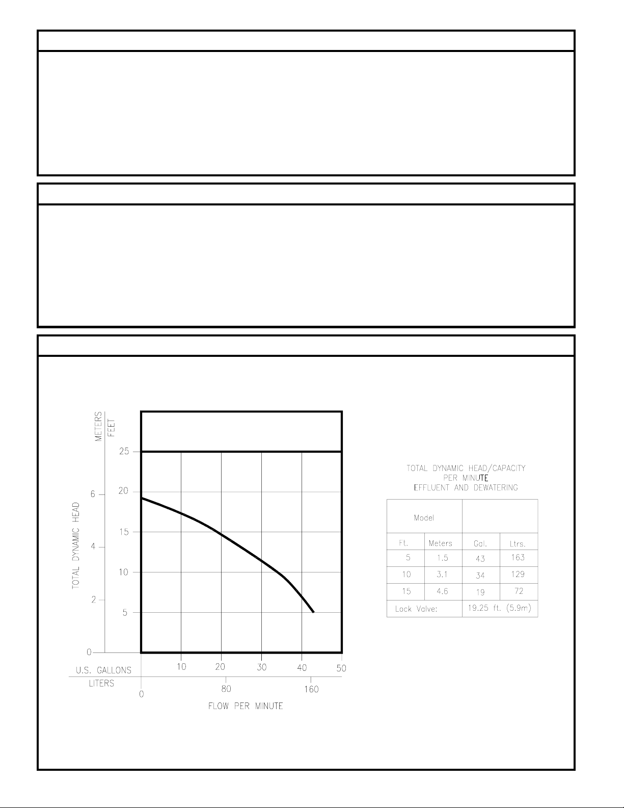
Performance Characteristics
6. Test operation of pump per STEP 5.
7. Do not over tighten bushing, check valve, or hose clamp.
8. Plug pump into a properly grounded, constant voltage source.
9. Do not plug into a device that runs intermittently.
10. Obtain model number and date code prior to calling factory.
NOT carry or lift pump by its power cord. DO NOT use an extension cord
with this Crawl Space Pumping System.
5. DO NOT use a discharge pipe smaller than the diameter of the hose kit.
6. DO test pump immediately after installation to be sure that the system is
working properly.
7. DO review all applicable local and national codes and verify that the
installation conforms to each of them.
Crawl Space Pumping System
HEAD CAPACITY CURVE
CRAWL
SPACE
009897
© Copyright 2002. All rights reserved.
2
Page 3

STEP 1 Site Selection for Drain Basin
Note: If freezing of the discharge line is possible, refer to Step 6.
1.1) Select a location that is a low spot or an area that naturally
collects water. Refer to Figure 1.1. Grade crawl space so
water will drain toward pit. Place plastic sheeting on
ground.
Note: If weep tiles or drain lines are to be used, then select a basin
location that will provide the most efficient drainage.
Figure 1.1
STEP 2 Installation of Basin (Typical Crawl Space Application)
Note: Proceed to STEP 2A if installing Slotted basin with extension kit.
2.1) Excavate the site to the dimension shown in Figure 2.1.
Note: If weep tiles or drain lines are to be used, rough-in plumbing should be completed at
this time.
2.2) Lower basin into pit (Refer to Figure 2.2). Complete installation of weep or drain lines.
Figure 2.1
SK1798
Figure 2.2
STEP 2A Installation of Slotted Basin with Optional Extension Kit
2A.1) Excavate the site to the dimensions shown in Figure 2A.1.
Note: If weep tiles or drain lines are to be used, rough-in plumbing should be completed
at this time.
2A.2) Attach the extension to the basin with the four bolts provided in the extension kit.
Refer to Figure 2A.2.
2A.3) Lower basin into pit and complete the installation of weep tiles or drain lines. Refer
to Figure 2A.3.
Note: If concrete is to be poured around the top of the extension, then make the pit depth
34½ to provide for access.
Extension Kit is an Accessory
Item and must be purchased
separately.
Figure 2A.2
SK1800
SK1802
Figure 2A.1
SK1801
© Copyright 2002. All rights reserved.
3
SK1803
Figure 2A.3
Page 4

STEP 3
Installation of Pump and Cover
3.1) Attach the flexible discharge hose to pump and lower into pit.
3.2) Attach lid and complete discharge line connections.
Note: Do not modify the Slotted basin lid. However, if extension kit is used, then it will
be necessary to drill ½ dia. inlet drain holes in the extension kit lid. Refer to Figure 3.2.
Note: After modification, attach the lid to the extension with 4 self-threading sheet metal
screws (included).
DO NOT USE LID SUPPLIED WITH SLOTTED BASIN IF USING
EXTENSION KIT.
Extension Kit is an
Accessory Item and must
be purchased separately.
Figure 3.1 Figure 3.2
STEP 4
4.1) Backfill pit as shown in Figure 4.1 & 4.2.
Backfill Pit
Extension Kit is an
Accessory Item and must
be purchased separately.
SK1799
Figure 4.1
SK1807
Figure 4.2
© Copyright 2002. All rights reserved.
4
Page 5

STEP 5
5.1) Plug in pump.
5.2) Pour water through lid until pump comes on.
5.3) Check all discharge line connections for leaks or obstructions.
5.4) If the pump begins to short cycle as described in part C of the troubleshooting guide, then it will be necessary to install a check valve in the discharge line.
This will prevent water from draining from the discharge line back into the pit. Refer to Figure 5.1. If a check valve is installed, the discharge pipe must be protected
from freezing. Refer to Step 6 for freezing protection.
5.5) If after completing the above procedures the system is not operating properly, refer to the Trouble Shooting Guide.
Testing of System
SK1805
Figure 5.1
STEP 6
Note: If there is the possibility of the discharge line freezing, then install the discharge line as recommended in Figure 6.1.
Freezing Protection
SK1822
Figure 6.1
© Copyright 2002. All rights reserved.
5
Extension Kit is an
Accessory Item and must
be purchased separately.
Page 6

Replacement Parts List
REF.
NO.
DESCRIPTION NOTES
QTY
Present
1 Pump 1 014729
2 Slotted Basin 1 012172
3 Lid 1 012173
4 Hose Kit 1 014732
6/98
to
SK1858
SK1824
SK1823
© Copyright 2002. All rights reserved.
6
Page 7

Trouble Shooting Guide
Condition Possible Cause Remedy
A. PUMP WILL NOT START OR RUN.
B. PUMP TRIPS OVERLOAD OR
BLOWS FUSE.
C. PUMP STARTS AND STOPS TOO
OFTEN.
Blown fuse.
Low voltage.
Thermal overload open.
Impeller bound.
Motor or wiring shorted.
Switch defective.
Damaged float.
Float assembly bound.
Incorrect voltage.
Impeller bound.
Motor shorted.
Short cycling (No check valve in discharge line to prevent water from draining back into pit).
Have a qualified electrician check circuit.
Contact an Authorized Service Station.
Check for debris around float.
Have qualified electrician check circuit.
Contact an Authorized Service Station.
Refer to STEP 5 for installation of check valve.
Defective float.
E. PUMP WILL NOT SHUT OFF.
F. PUMP OPERATES BUT DELIVERS
LITTLE OR NO WATER.
Before servicing a pump, always shut off the main
power breaker and then unplug the pump - making sure you are
not standing in water and are wearing insulated, protective-sole
shoes. Under flooded conditions, contact your local electric
company or a qualified licensed electrician for disconnecting
electrical service prior to pump removal.
Debris under float.
Switch defective.
Switch out of adjustment.
Weep hole plugged (Air-locked).
Obstruction in discharge line.
Discharge head exceeds capacity.
Low voltage.
Discharge line frozen.
Contact an Authorized Service Station.
Remove debris as necessary.
Contact an Authorized Service Station.
Clear weep hole as necessary.
Clear lines as necessary.
Refer to pump performance chart on page 2,
or contact factory.
Have qualified electrician check circuit.
Clear and protect from freezing (See STEP 6).
If the above checklist does not solve the problem, consult our
Technical Service Department. Do not attempt to service or
otherwise disassemble pump.
© Copyright 2002. All rights reserved.
7
Page 8

Manufacturers of . . .
Quality Products since 1866
95 N. Oak St. Kendallville, IN 46755
1-800-345-9422
© Copyright 2002. All rights reserved.
8
 Loading...