

Page 1
Manufacturers of . . .
“Quality Products since 1866”
INSTALLATION IN STRUC TIONS
95 N. Oak St. • Kendallville, IN 46755
1-800-345-9422
DRAINMAKER
FW0107
110 4
Supersedes
0704
MODEL:_______________________
DATE CODE: __________________
DATE INSTALLED: _____________
PREINSTALLATION CHECK LIST
Notice to Installer: Instructions must remain with installation.
1. Inspect your unit. Occasionally, prod ucts are dam aged during ship ment. If the unit is damaged, contact your dealer before using.
Do Not remove the test plug from the pump.
2. Carefully read the literature provided to familiarize yourself with specifi c details regarding installation and use. These materials should
be re tained for future reference.
SEE BELOW FOR LIST OF WARNINGS
1. To reduce the risk of elec tri cal shock, a prop er ly ground ed
receptacle of grounding type must be in stalled and pro tect ed
by a ground fault circuit in ter rupt er (GFCI) and in ac cor dance
with National Electrical Code and lo cal codes.
2. Make certain that the receptacle is with in the reach of the pump’s
pow er supply cord. DO NOT USE AN EX TEN SION CORD.
Extension cords that are too long or too light do not deliver
suf fi cient voltage to the pump motor. But more im por tant, they
could present a safety hazard if the insulation were to become
damaged or the con nec tion end were to fall into the sump.
3. Testing for Ground. As a safety mea sure, each elec tri cal outlet
should be checked for ground using an Un der writ ers Lab o ra to ry
Listed circuit analyzer which will in di cate if the pow er, neutral
and ground wires are correctly con nect ed to your out let. If they
are not, call a qualifi ed elec tri cian.
4. For Added Safety. Pump must be con nect ed to a 3-prong
ground ed outlet in ter rupt er de vice (ground fault cir cuit in ter rupt er).
5. FOR YOUR PROTECTION, ALWAYS DIS CON NECT PUMP
FROM ITS POWER SOURCE BEFORE HAN DLING. Sin gle
phase pumps are supplied with a 3-prong ground ed plug to help
protect you against the pos si bil i ty of elec tri cal shock. DO NOT,
UNDER ANY CIR CUM STANC ES, RE MOVE THE GROUND
PIN. To re duce the risk of electrical shock, a properly grounded
re cep ta cle of ground ing type must be installed and pro tect ed
by a ground fault circuit interrupter (GFCI) in ac cor dance with
national elec tri cal code and local codes.
6. Installation and checking of electrical cir cuits and hard ware
should only be performed by a qualifi ed licensed electrician.
7. Risk of electric shock - These pumps have not been in ves ti gat ed
for use in swimming pool areas.
8. According to the state of California (Prop 65), this product
contains chemicals known to the state of California to cause
cancer and birth defects or other reproductive harm.
1. Check to be sure your power source is adequate for handling
the voltage requirements of the motor, as in di cat ed on the
pump or basin plate.
2. Make sure the pump electrical supply cir cuit is equipped with
fuses or circuit breakers of proper ca pac i ty. A sep a rate branch
circuit is rec om mend ed, sized ac cord ing to the National Elec tri cal Code for the current shown on the pump name plate.
3. All plumbing (discharge and vent lines) must be in stalled to
meet local codes. Unit must be vented. DO NOT USE AN
AU TO MAT IC PLUMBING VENT DEVICE SIM I LAR TO A
"PRO-VENT". Some states require this product to be installed
by a licensed plumb er.
4. Repair and service should be performed by an au tho rized
service station only.
5. CHECK VALVE MUST BE USED TO RE DUCE UN NEC ES SARY CYCLING OF PUMP. Check valve must be pur chased sep a rate ly.
6. Dewatering pumps are not designed or intended for han dling
raw sewage.
7. Maximum operating temperature must not exceed 77°F
(25°C).
8. For health reasons, do not unplug, turn off, or disable pump
and use pump tank system as a way to fi ll up a sink or laundry
tray, etc.
9. Unit is designed for above ground installation only.
NOTE: Pumps with the “UL” mark and pumps with the “US” mark
SEE BELOW FOR LIST OF CAUTIONS
are tested to UL Standard UL778. CSA Certifi ed pumps are
certifi ed to CSA Standard C22.2 No. 108.
Product information presented here re fl ects con di tions at time of publication. Consult factory re gard ing dis crep an cies or in con sis ten cies.
© Copyright 2004. All rights reserved.
1
Page 2
Ten Helpful Hints For Easy Installation
1. Read all instructions before beginning in stal la tion.
2. Be certain that basin is on a fi rm level surface.
3. Do not use an automatic plumbing vent device.
4. Do not over-torque lid attachment screws.
5. Always use a check valve on the discharge line.
6. Test operation of pump per STEP 6.
Do’s And Don't’s For Installing A Unit
1. DO read all installation material included with the
pump.
2. DO inspect unit for any visible damage caused by shipping. Contact dealer if unit appears to be damaged.
3. DO clean all debris from the basin and pump.
4. DO always disconnect pump from power source before
han dling. DO always connect to a separately protected
and prop er ly grounded ground fault protected circuit.
DO NOT ever cut, splice or damage power cord. DO
NOT carry or lift pump by its power cord. DO NOT use
an extension cord.
7. Always provide some means to disconnect basin from
plumb ing for maintenance purposes.
8. Run unit at least once a month to verify proper op er a tion.
9. The model number and date code can be found on
the lid warning label.
10. Plug pump into a properly grounded GFCI receptacle.
5. DO NOT use a discharge pipe smaller than the pump
discharge size.
6. DO test pump immediately after installation to be sure
that the system is working properly.
7. DO review all applicable local and national codes and
verify that the installation conforms to each of them.
8. DO NOT install unit in the ground.
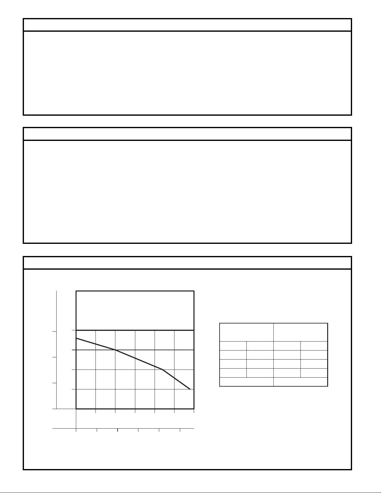
Performance Characteristics for the Pump in the DrainMaker System
TOTAL DYNAMIC HEAD/FLOW
METERS
FEET
20
6
15
4
10
TOTAL DYNAMIC HEAD
2
0
GALLONS
LITERS
PUMP PERFORMANCE CURVE
5
510
0
20 40
DRAINMAKER
15
FLOW PER MINUTE
20
Feet Meters
5
10
15 4.6
Shut-off Head:
25
8060
30
100
PER MINUTE
DEWATERING ONLY
MODEL
1.5
3.0
1048
Gal. Liters
29
22
10 38
18 ft. (5.5m)
110
83
009961BFW
009961AFW
© Copyright 2004. All rights reserved.
2
Page 3
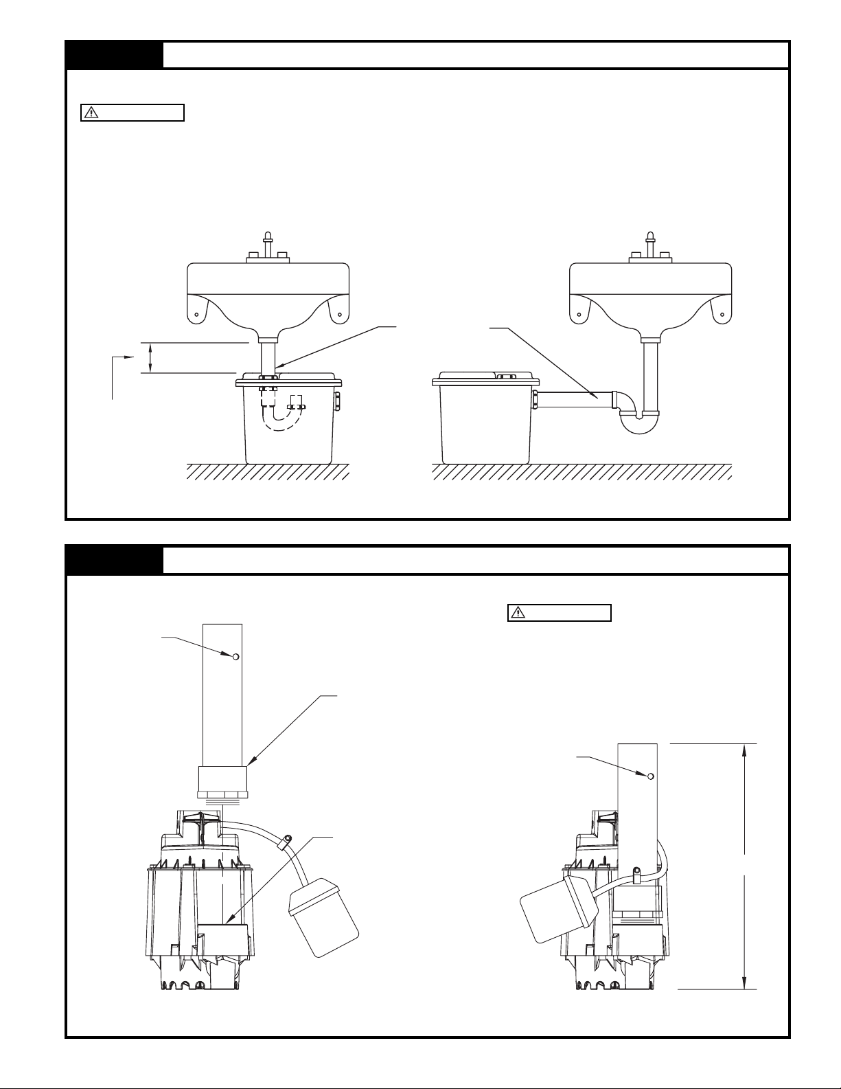
STEP 1 Determine Installation Confi guration
NOTE: The basin is designed to be installed directly under the sink (Internal Trap) or on the side (standard)
IMPORTANT!
Check local and state codes before using the internal trap option.
1.1) Figure 1.1A and 1.1B are typical confi gurations for installation of the drain systems. The actual confi guration
will vary depending on your cabinet and sink confi guration.
NOTE: If installing the internal trap, record the “x” dimension, it will be required in Step 4.
INTERNAL TRAP COMPONENTS SUPPLIED BY OTHERS.
PIPING SHOWN ONLY
FOR CLARITY.
X (4" MIN.)
SEE NOTE
Figure 1.1A
INTERNAL TRAP
STANDARD (EXTERNAL TRAP)
Figure 1.1B
STEP 2 Install the Discharge Pipe onto the Pump
IMPORTANT!
BE SURE THAT WEEP
WEEP HOLE
DISCHARGE PIPE
PUMP DISCHARGE
HOLE IS NOT DIRECTED TOWARD THE
FLOAT!
Water stream will be visible from this
hole during pump run periods.
WEEP HOLE
SK2001
11 3/8"
Figure 2.1
© Copyright 2004. All rights reserved.
3
SK2022
Page 4

STEP 2A Installation of the Float Assembly
2A.1) Install the fl oat as shown in Figure 2A.1 and Figure 2A.2.
WEEP HOLE
DISCHARGE PIPE
IMPORTANT!
FLOAT MUST BE
TETHERED IN THE ORIENTATION SHOWN
IN FIGURE 2A.2.
Water stream will be visible from this hole
during pump run periods.
2 1/4"
DRILL 3/16"
CAP
Figure 2A.1
THRU HOLE
6"
DRILL
Figure 2A.2
STEP 3 Installation of the Foam Gasket
3.1) Install the foam gasket into the “gasket seat” at the top of the basin, refer to Figure 3.1 for details.
OVERLAP DETAIL
FOAM GASKET
CAP
DISCHARGE PIPE
SK2009
GASKET SEAT
Figure 3.1
© Copyright 2004. All rights reserved.
4
APPROXIMATELY 1/4" OVERLAP
GASKET SEAT DETAIL
FOAM GASKET
BASIN
SK2003
Page 5

STEP 4 Internal Trap Installation Only
4.1) Cut the tailpipe to the dimension determined in Figure 4.1.
4.2) Install the sink drain components to the lid as shown in Figure 4.2.
4.3) Orient the lid assembly as shown in Figure 4.3 and secure the trap components.
(HAND TIGHTEN the assembly to the lid at this time. Adjustment will be required in Step 5.)
Note: To insure a proper water seal, the extension must be installed as shown in the “trap detail”.
INTERNAL TRAP COMPONENTS SUPPLIED BY OTHERS.
TRAP DETAIL
TAILPIPE
LENGTH
Figure 4.1
TAIL PIPE
X
4 1/2"
DIMENSION MEASURED
IN STEP 1.
TAIL PIPE
INLET
TRAP
4"
FLANGED TAIL PIPE
(SEE NOTE)
Figure 4.2
TRAP DISCHARGE PARTIALLY
VISIBLE THROUGH THE CORD
SEAL OPENING.
DISCHARGE
CORD SEAL OPENING
VENT
Figure 4.3
SK2004
© Copyright 2004. All rights reserved.
5
Page 6

STEP 5 Final Assembly
NOTE: External plumbing confi guration will vary depending on the location of basin, location of main stack
and available space.
5.1) Place the pump in the basin as shown in Figure 5.1.
NOTE: If installing the internal trap, rotate the tail pipe to the orientation shown in Figure 5.1.
5.2) Install the lid components as shown in Figure 5.2.
NOTE: Pull excess cordage through the opening and install the cordseal as shown in Figure 5.3A.
Ensure o-ring is in the cap before installation.
5.3) Place the basin assembly in its fi nal position and complete plumbing. Secure all connections
(shown in 5.3A or 5.3B).
KEY
Figure 5.1
(PURCHASED SEPARATELY)
CORD SEAL
GFCI
OUTLET
UNION
INLET
SK2005
TRAP INLET
O-RING
CHECK VALVE
CAP
SK2007B
CAP SECTION VIEW
*
CORD SEAL
SEE NOTE
O-RING
CAP
(PURCHASED SEPARATELY)
GFCI
OUTLET
UNION
CAP
CORD SEAL
INLET
2" SLP x NPT
Figure 5.2
1 1/2" SLP x NPT
(APPLY SEALANT TO THREADS)
1/4 - 20 x 1"
S.S. SCREWS
1/4 - 20 STD.
S.S. FLAT WASHERS
DISCHARGE PIPE
1/4 - 20 STD.
S.S. FLAT WASHERS
1/4 - 20
S.S. NUTS
(TORQUE TO 30 IN-LB)
DISCHARGE PIPEDISCHARGE PIPE
SK2007A
*
CHECK VALVE
CAP
INTERNAL TRAP INSTALLATION STANDARD INSTALLATION
Figure 5.3A Figure 5.3B
SK2006
*
CHECK VALVE MUST BE
PURCHASED SEPARATELY
STEP 6 Initial Testing of Drain Basin System
6.1) Plug the cord into a properly grounded GFCI receptacle.
6.2) Fill tank with water.
6.3) Check all plumbing for leaks as the basin fi lls.
6.4) Verify that the pump starts and stops.
6.5.) Check the discharge line for leaks as the pump empties the basin.
6.6.) Repeat steps 6.2 to 6.5 as necessary to insure proper operation.
6.7.) If problems persist refer to the troubleshooting guide located at the back of the manual.
© Copyright 2004. All rights reserved.
6
SK2006
Page 7

Illustrated Parts Breakdown
9
10
11
CHECK VALVE
(PURCHASED
SEPARATELY)
6
8
5
4
15
14
7
12
1
DRAINMAKER
08/00
ITEM DESCRIPTION QUANTITY thru
Current
1 Drain Pump 1 1104RP
2 Md. "WM1048" 1 014725
3 Basin - Tank 1 013017
4 Discharge Tube 1 013732
5 Basin - Lid 1 013018
6 Hard ware Pack 1 013733
7 Basin Seal 1 N/A*
8 Unicheck 1 N/A
9 ¼ - 20X1" lg. RHM Screw S.S. 8 N/A*
10 ¼ - Flat Washer S.S. 16 N/A*
11 ¼ - 20 Hex. Hd. Nut - S.S. 8 N/A*
12 Pipe Cap w/o-ring 1 N/A*
13 O-Ring 1 N/A*
14 Nylon Cable Tie 5/16” 1 N/A*
15 Self Tapping Screw#10x.375 1 N/A*
13
3
2
SK2008
* When ordering this item order the hardware pack item #6.
© Copyright 2004. All rights reserved.
7
Page 8

Service Checklist
ELECTRICAL PRECAUTIONS- Before servicing a pump, always shut off the main power breaker and then unplug the pump - making sure you are not standing in water and wearing insulated protective sole shoes. Under fl ooded conditions, contact your local electric company or a
qualifi ed licensed electrician for disconnecting electrical service prior to pump removal.
Submersible pumps contain oil which becomes pressured and hot under operating conditions — allow 2½ hours after disconnecting before
attempting service.
CONDITION
COMMON CAUSES
A. Pump will not start or run.
B. Motor overheats and trips over load
or blows fuse.
C. Pump starts and stops too often.
D. Pump will not shut off.
E. Pump operates but delivers little
or no wa ter.
F. Drop in head and/or capacity after
a period of use.
G. If tank or fi ttings leak.
If the above checklist does not uncover the problem, consult the factory - Do not attempt to service or otherwise disassemble pump.
Check fuse, low voltage, over load open, open or incorrect wiring, open switch, impeller or seal bound me chan i cal ly,
defective capacitor or relay when used, motor or wiring shorted. Float assembly held down. Switch defective,
dam aged, or out of adjustment.
Incorrect voltage, negative head (discharge open lower than normal) impeller or seal bound mechanically, defective capacitor or relay, motor shorted.
Float switch tether length too short, check valve stuck, or none installed in long distance line, over load open,
switch defective.
Debris under fl oat assembly, fl oat bound by pit sides or other, switch de fec tive, damaged or out of adjustment.
Check strainer housing, discharge pipe, or if check valve is used, the vent hole must be clear. Dis charge head
ex ceeds pump capacity. Low or incorrect voltage. Incorrect motor rotation. Ca pac i tor defective. Incoming water
con tain ing air or causing air to enter pump ing chamber.
Increased pipe friction, clogged line or check valve. Abrasive material and ad verse chem i cals could possibly
deteriorate impeller and pump housing. Check line. Remove base and inspect.
Carefully tighten pipe joints (use pipe dope) and screws. Check gasket location, tighten lid evenly. Do not over
tighten fi ttings or screws.
Manufacturers of . . .
“Quality Products since 1866”
95 N. Oak St. • Kendallville, IN 46755
1-800-345-9422
© Copyright 2004. All rights reserved.
8
 Loading...