

Page 1
STAR
®
FW1591
0113
Supersedes NEW
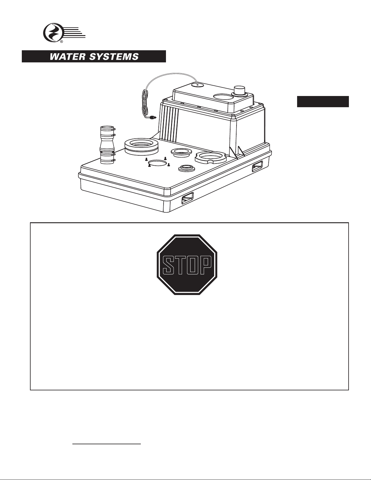
BATHROOM ADD-ON SYSTEM
Patent No. 5,038,418
MODEL #
Español p. 20
S1101
For missing, damaged parts or technical help, Call
1-800-742-5044
For replacement pump, order 1102RP
or see complete repair parts list on page 17
ATTACH YOUR RECEIPT HERE
Purchase Date
STOP
before returning product
P/N 152521
1
Page 2
TABLE OF CONTENTS
Safety Information ............................................................................................................................2
Package Contents ............................................................................................................................4
Preparation .......................................................................................................................................5
General Pump Uses .........................................................................................................................5
Dimensions .......................................................................................................................................6
Pump System Location.....................................................................................................................6
Bolt Location .....................................................................................................................................7
Testing Operation .............................................................................................................................8
Connect to Plumbing ........................................................................................................................9
Installation of Toilet - Exposed Installation ...................................................................................... 11
Installation of Toilet - Hidden Installation ........................................................................................ 11
Additional Fixtures ..........................................................................................................................13
Replacement Parts .........................................................................................................................17
Troubleshooting ..............................................................................................................................18
Spotting Template ........................................................................................................................... 19
SAFETY INFORMATION
Please read and understand this entire manual before attempting to assemble, operate or install the
product.
Inspect all materials before installation. If parts are damaged or missing, call 1-800-742-5044 before
returning to your retailer.
DANGER
ELECTRICAL SHOCK HAZARD.
Always disconnect power source before performing any work on or near the motor or its
connected load. If the power disconnect point is out-of-sight, lock it in the open position and tag it
to prevent unexpected application of power. Failure to do so could result in fatal electrical shock.
ELECTRICAL SHOCK HAZARD.
Do not handle the pump with wet hands or when standing in water as fatal electrical shock could
occur. Disconnect main power before handling unit for ANY REASON!
RISK OF ELECTRIC SHOCK.
These pumps have not been investigated for use in swimming pool areas.
2
Page 3
SAFETY INFORMATION
WARNING
ELECTRICAL SHOCK ALERT.
To reduce the risk of electric shock, install only a circuit protected by a ground-fault circuit-interrupter
(GFCI). Make certain that the ground fault receptacle is within the reach of the pump’s power supply
cord. DO NOT USE AN EXTENSION CORD.
ELECTRICAL SHOCK ALERT.
Follow all local electrical and safety codes, as well as the National Electrical Code (NEC) and the
Occupational Safety and Health Act (OSHA).
ELECTRICAL SHOCK ALERT.
Do not kink power cable and never allow the cable to come in contact with oil, grease, hot surfaces,
chemicals or sharp objects. Replace damaged or worn wiring cord immediately.
ELECTRICAL SHOCK ALERT.
As a safety measure, each electrical outlet should be checked for ground using an Underwriters
Laboratory Listed circuit analyzer which will indicate if the power, neutral and ground wires are
correctly connected to your outlet. If they are not, contact a licensed electrician.
ELECTRICAL SHOCK ALERT.
These pumps are supplied with a 3-prong grounded plug to help protect you against the possibility
of electrical shock. DO NOT UNDER ANY CIRCUMSTANCES REMOVE THE GROUND PIN.
ELECTRICAL SHOCK ALERT.
Make sure the pump electrical supply circuit is equipped with fuses or circuit breakers of proper
capacity. A separate branch circuit is recommended, sized according to the National Electrical
Code for the current shown on the pump nameplate.
CHEMICAL ALERT.
This product contains chemicals known to the state of California to cause cancer and birth defects
or other reproductive harm.
CAUTION
PRODUCT DAMAGE MAY RESULT
Make certain the power source conforms to the requirements of your equipment.
PRODUCT DAMAGE MAY RESULT
Maximum continuous operating water temperature for standard model pumps must not exceed 130°F (54°C).
PRODUCT DAMAGE MAY RESULT
Do not use an automatic plumbing vent device such as a “Pro-Vent.” Some states require this product to be
installed by a licensed plumber.
• NOTE: Pumps with the “UL” mark and pumps with the “US” mark are tested to UL Standard
UL778. CSA certied pumps are certied to CSA Standard C22.2 No. 108. (CUS.)
• Do not use wax seal that includes a ange that extends into the tank. If a oor is installed over the
tank, use the oor ange extender seal kit included with the system.
• For installation below the original oor line, call 1-800-742-5044.
3
Page 4
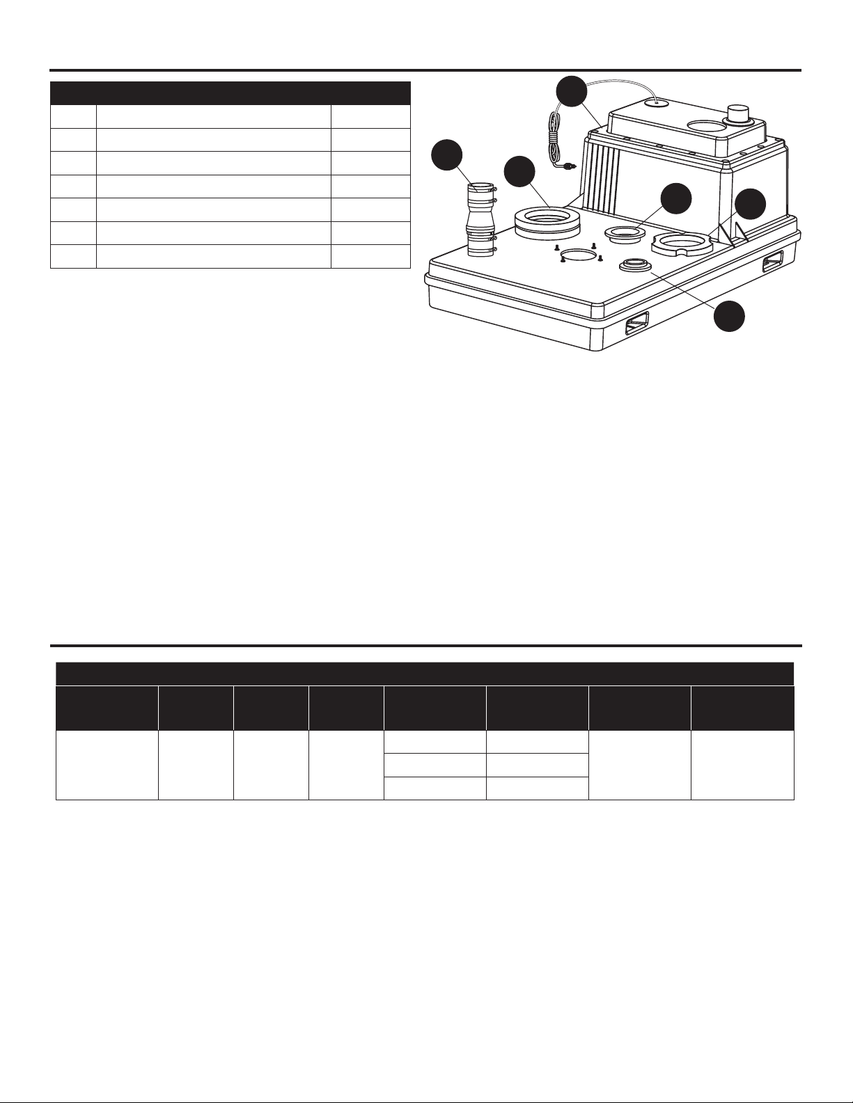
PACKAGE CONTENTS
Part Description Quantity
A Pre-assembled Pump System 1
B 2 in. Pipe Seal for 3 in. hole 2
C 2” Check Valve 1
D 3 in. Pipe Seal for 4 in. hole 1
E Wax Ring 2
F Locator Ring 1
* Hardware Pack 1
*Not Shown
C
E
A
D
F
B
SPECIFICATIONS
PERFORMANCE
Model
Number
S1101 .4 1 115
NOTE: Be sure installation has a minimum of 5 ft. vertical head. Recommended for maximum of
13 ft. vertical head.
HP Phase Volts Ft. of Head Flow (GPM)
5 73
15 19
Shut Off
Head (Ft.)
17.5 2 in.10 39
Discharge
Size
4
Page 5
PREPARATION
Before beginning installation of product, make sure all parts are present. Compare parts with package
contents list. If any part is missing or damaged, do not attempt to assemble the product.
Estimated Installation Time: 5 hours for non-hidden installation or additional xtures.
Tools Required for Assembly (not included): tape measure, pipe tape, hacksaw, flathead screwdriver,
2-step PVC glue system (primer and sealer), hydraulic cement or other material
Parts Required For Assembly (not included): 2 in. Rubber coupling or union, 2 in. and 3 in. PVC pipe
and fittings as required to complete installation, shut-off valve as required by codes.
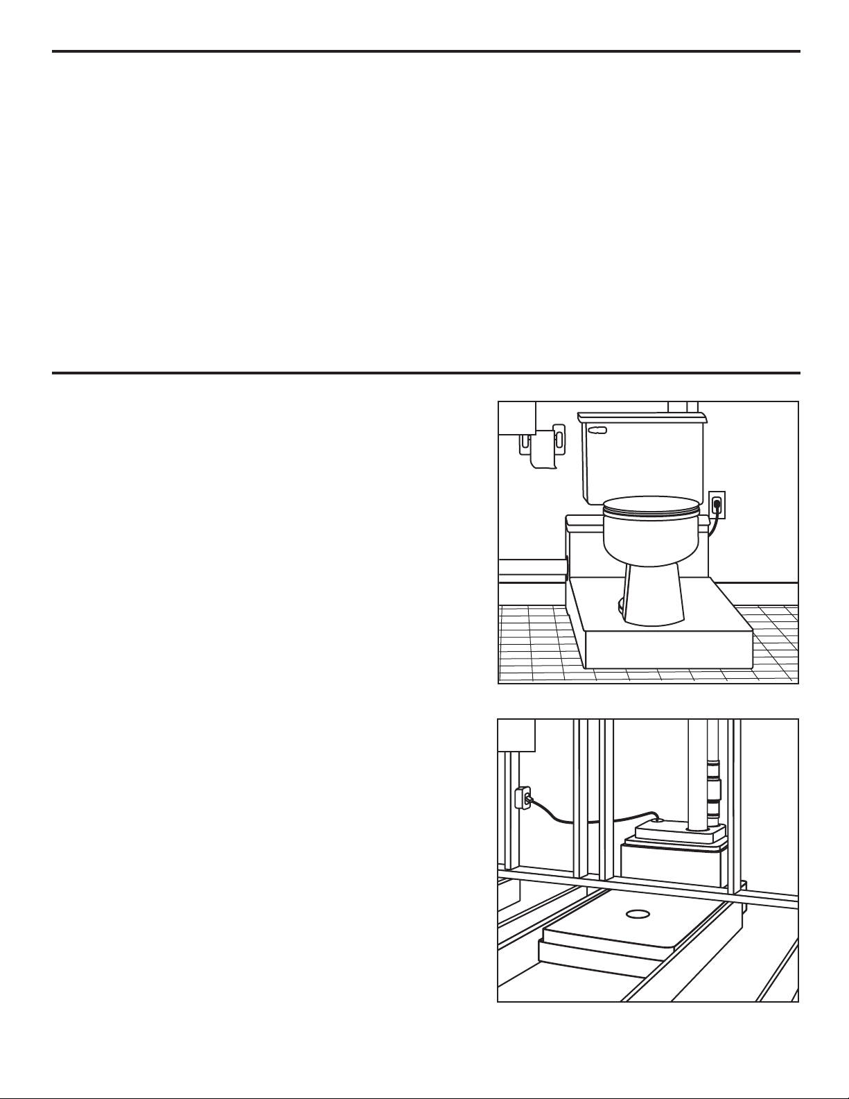
GENERAL PUMP USES
This pump system can be used in the following installations:
1. Exposed Installation (no subflooring is used).
2. Hidden Installation (subflooring is installed over unit).
1
2
5
Page 6
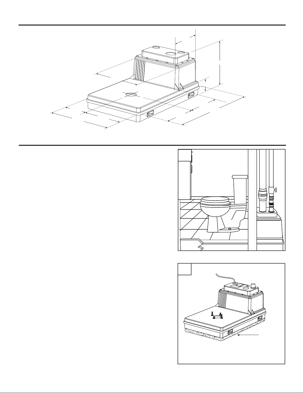
DIMENSIONS
All dimensions are in
inches.
20-1/2
12-1/4
24-1/2
12-1/4
LOCATION SELECTION AND LEVELING OF TANK
NOTE: If a built in installation is to be used, locate pump
chamber in an area that will allow access to the pump &
switch.
13-1/2
17
5-1/2
14-1/8
42-3/16
13-1/4
IL1653
1
1. Select a location which is readily accessible to the
existing discharge and vent lines.
2. Level tank to within 1/8 in. for length and width. Use
hydraulic cement or similar material for leveling.
CAUTION: Do not use wooden shims to level tank.
CAUTION: Ensure that nails, screws or other sharp
objects do not puncture tank
2
Level to
within
1/8 in.
6
Page 7
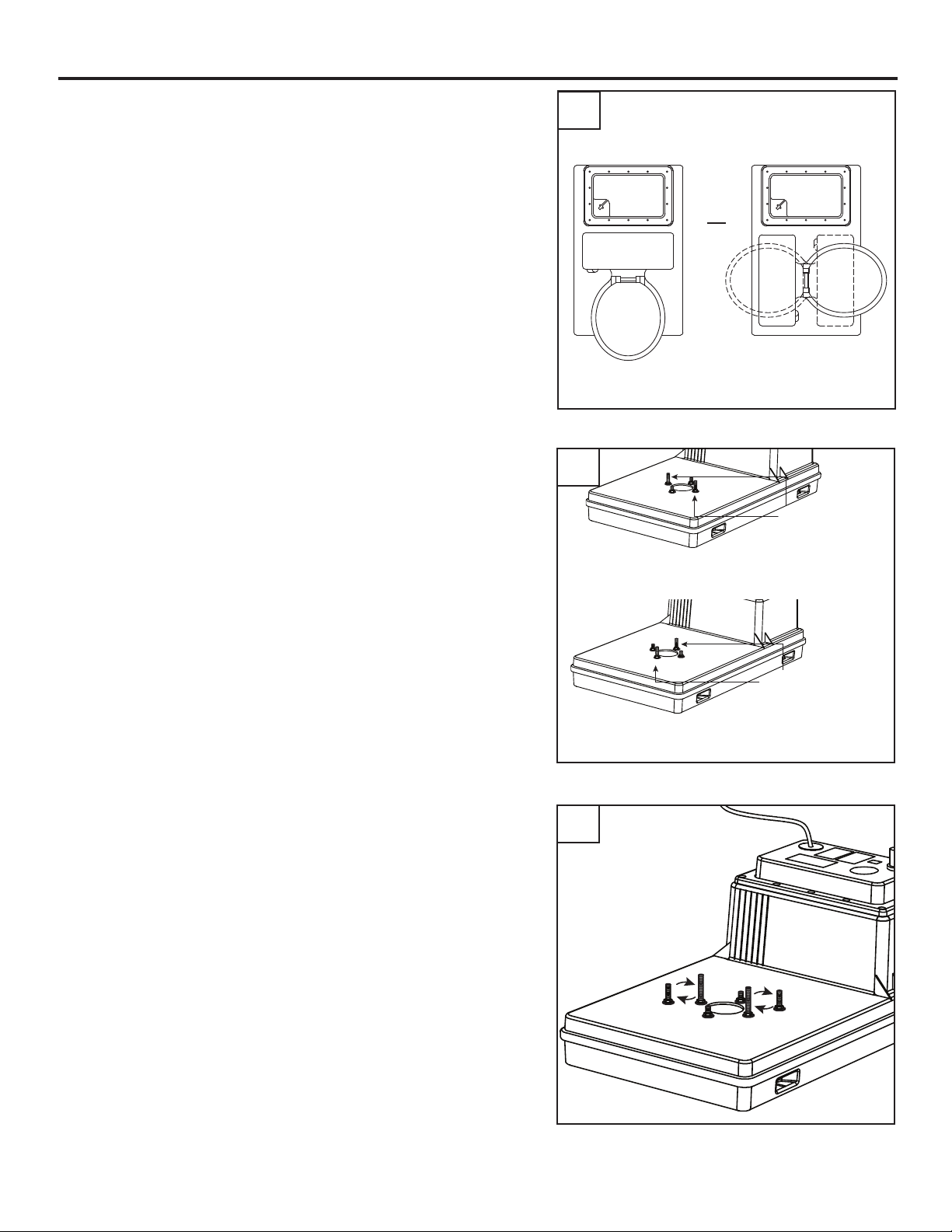
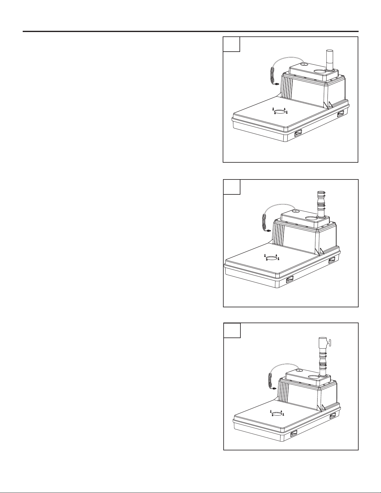
TOILET BOLT LOCATION
1. Determine how you will be placing the toilet on the
pump system. This determines the location of the long
bolts in step 2.
Note: Pump system ships preassembled in the forward
installation position.
If a side installation is desired, take note of the
2.
position of the 2 in. bolts and remove the all four bolts
located around toilet inlet hole in tank.
Rotate the location of each bolt 90 degrees around the
pre-drilled toilet installation hole and reinstall. Torque
screws to 25-30 in-lbs. DO NOT over-torque screws.
1
Side PositionForward Position
OR
2
2 in. bolt
location
for toilet in
foward mount
position
3. If subooring is installed, remove the 2 in. bolts located
around the toilet inlet hole in tank and replace with 3 in.
bolts from hardware pack.
2 in. bolt
location for
toilet in side
mount
position
3
7
Page 8
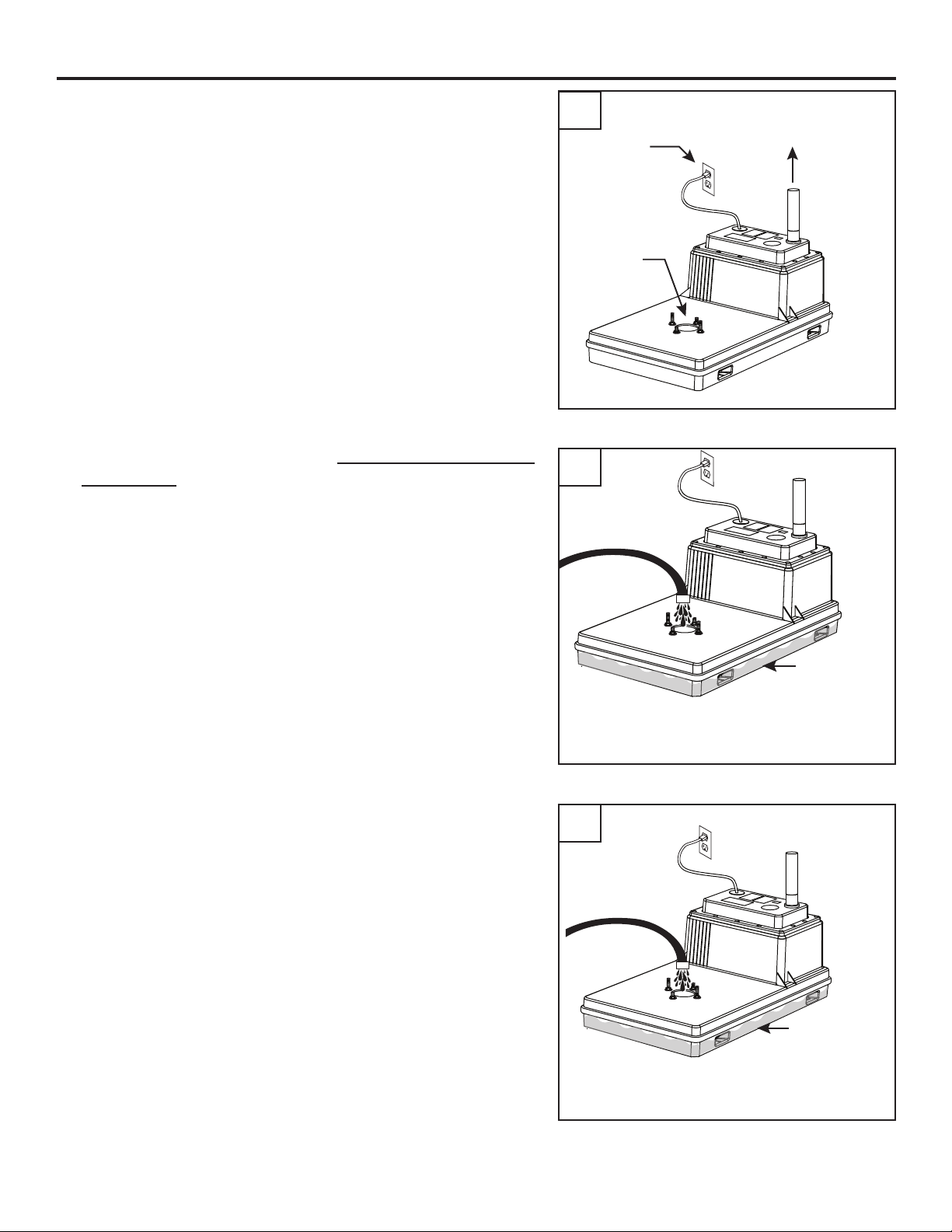
TESTING OPERATION
1. NOTE: Float switch on/off level has been preset
but should be checked by viewing through the toilet
inlet.
Temporarily connect the pump discharge pipe to the
house drain pipe and plug in pump
2. Fill the tank with 4 in. of water. Be sure the pump does
not turn on.
1
2
GFCI
Outlet
Toilet
Inlet
Temporary
Connection
To house
Drain
3. Add an additional 1/2 in. of water to the tank. The pump
should turn “ON” when the water level reaches 4-1/2
in. If “ON” level is correct, unplug pump, disconnect
temporary discharge piping and proceed to next section.
If “ON” level is incorrect, refer to Troubleshooting on
page 18.
4 in.
Water
3
4-1/2 in.
Water
8
Page 9
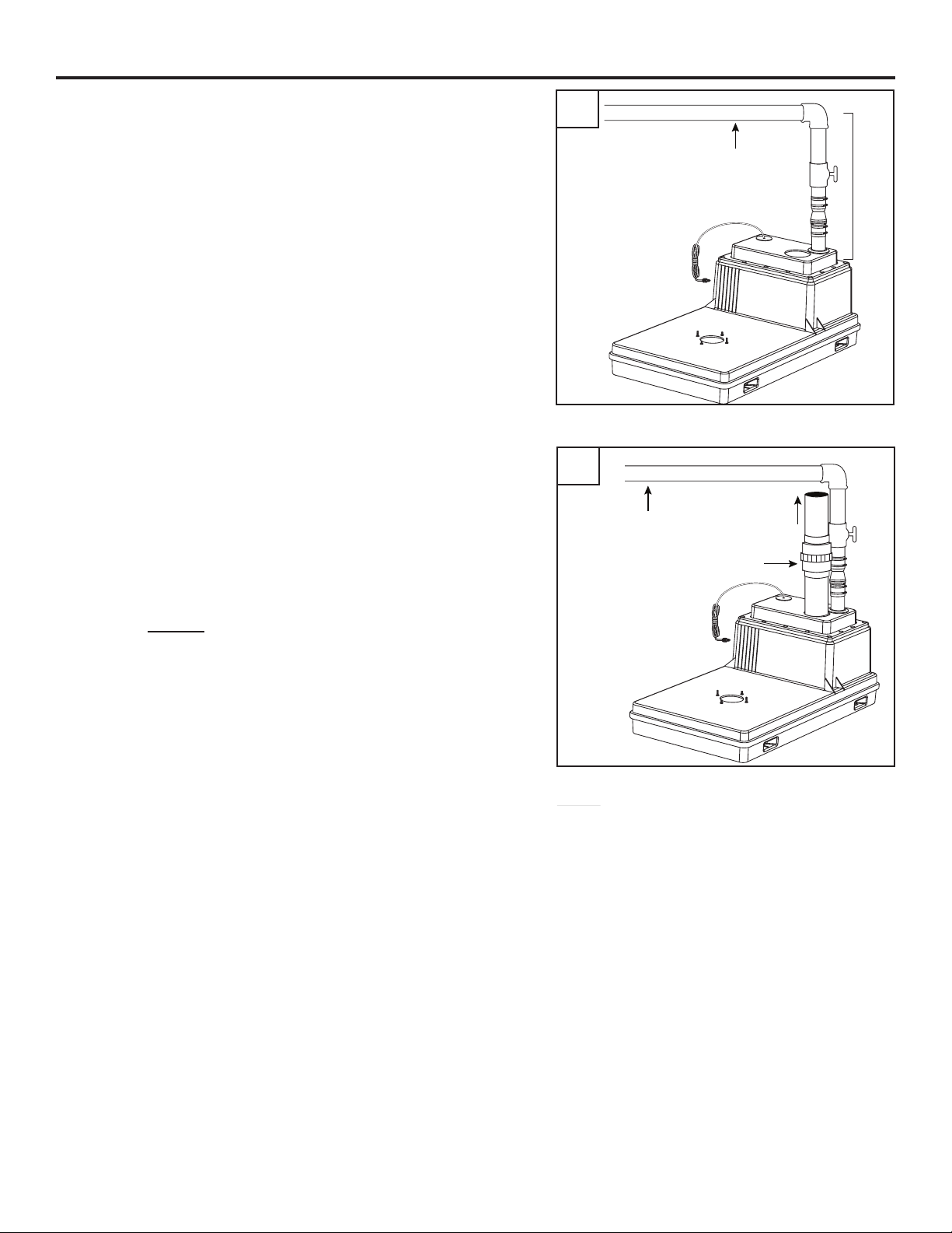
CONNECT TO PLUMBING
1. Install rigid 2 in. discharge pipe (not included) according
to local, regional and state codes. Use a 2-step PVC
glue system (not included) to join pipe and any ttings
needed.
CAUTION: Do not use a discharge pipe smaller than the
discharge pipe pre-installed in the system.
2. Install 2 in. check valve (included) in discharge pipe to
prevent back-ow.
CAUTION: Make sure the ow arrows on the check valve
are pointed up.
1
2
Discharge
Pipe
Check
Valve
3. Install 2 in. shut off valve (not included) above the
check valve in discharge pipe.
9
3
Shut
Off
Valve
Page 10
CONNECT TO PLUMBING
4. Connect discharge pipe into main waste line to sewer or
septic tank.
NOTE: Be sure discharge pipe has a minimum of 5 ft.
vertical head and a maximum of 13 ft. vertical head.
5. Connect rigid 3 in. vent pipe (not included) per local,
regional and state codes. Include a union in the line for
easy maintenance.
4
5
Main
waste line
Main
waste line
To Roof
Vent
5 Ft.
Min.
13 Ft.
Max.
NOTE: Check with local code authority if a reduction in
vent pipe size is desired.
CAUTION: Do Not use mechanical vent of any kind.
Union
10
Page 11
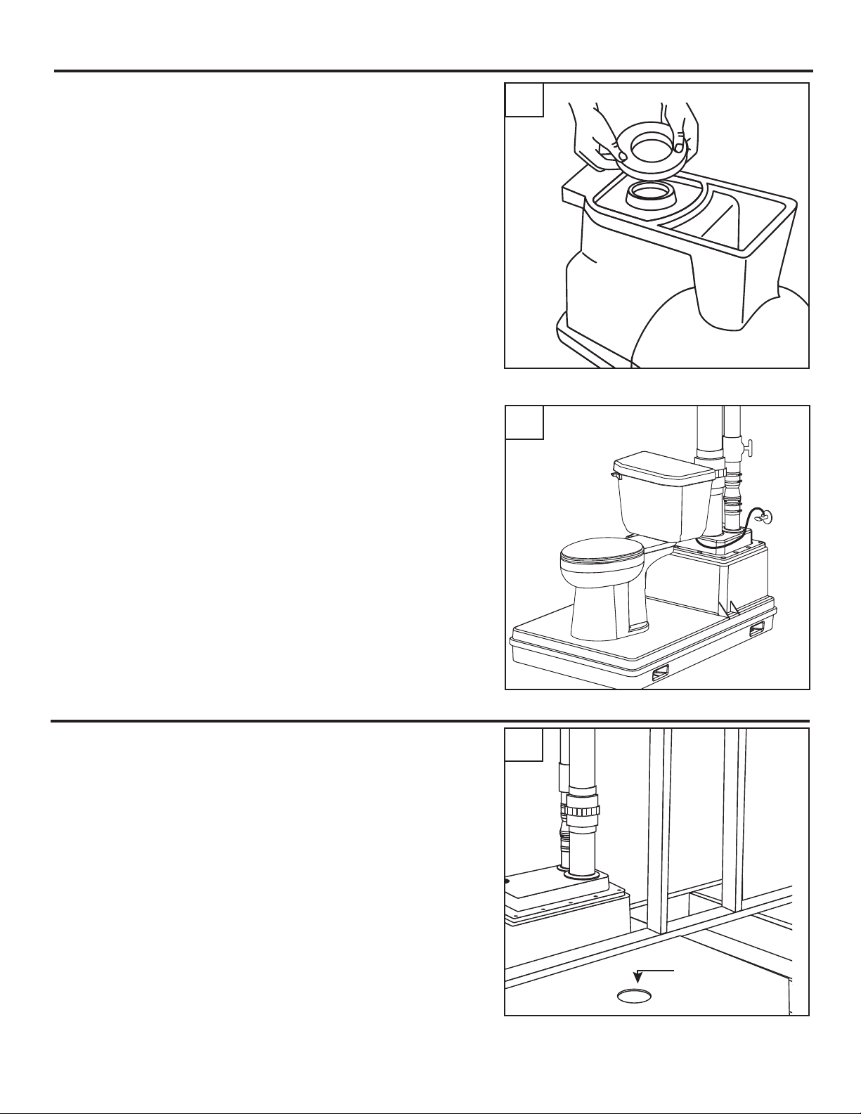
INSTALLATION OF TOILET - EXPOSED INSTALLATION
Exposed Installation (no subflooring is used)
1. Install 1 wax toilet bowl ring (included) and toilet as
described on the toilet ring carton.
2. Connect water line to toilet. Fill tank and test pump
system.
1
2
Water
Supply
INSTALLATION OF TOILET - HIDDEN INSTALLATION
1. Cut a 6-1/2 in. diameter hole in the suboor, centered
on the toilet tank opening in pump system.
NOTE: When using subooring, the 2 in. bolts pre-
installed in the tank must be replaced by the 3 in.
bolts included in the hardware kit.
11
1
6-1/2 in.
diameter hole
Page 12
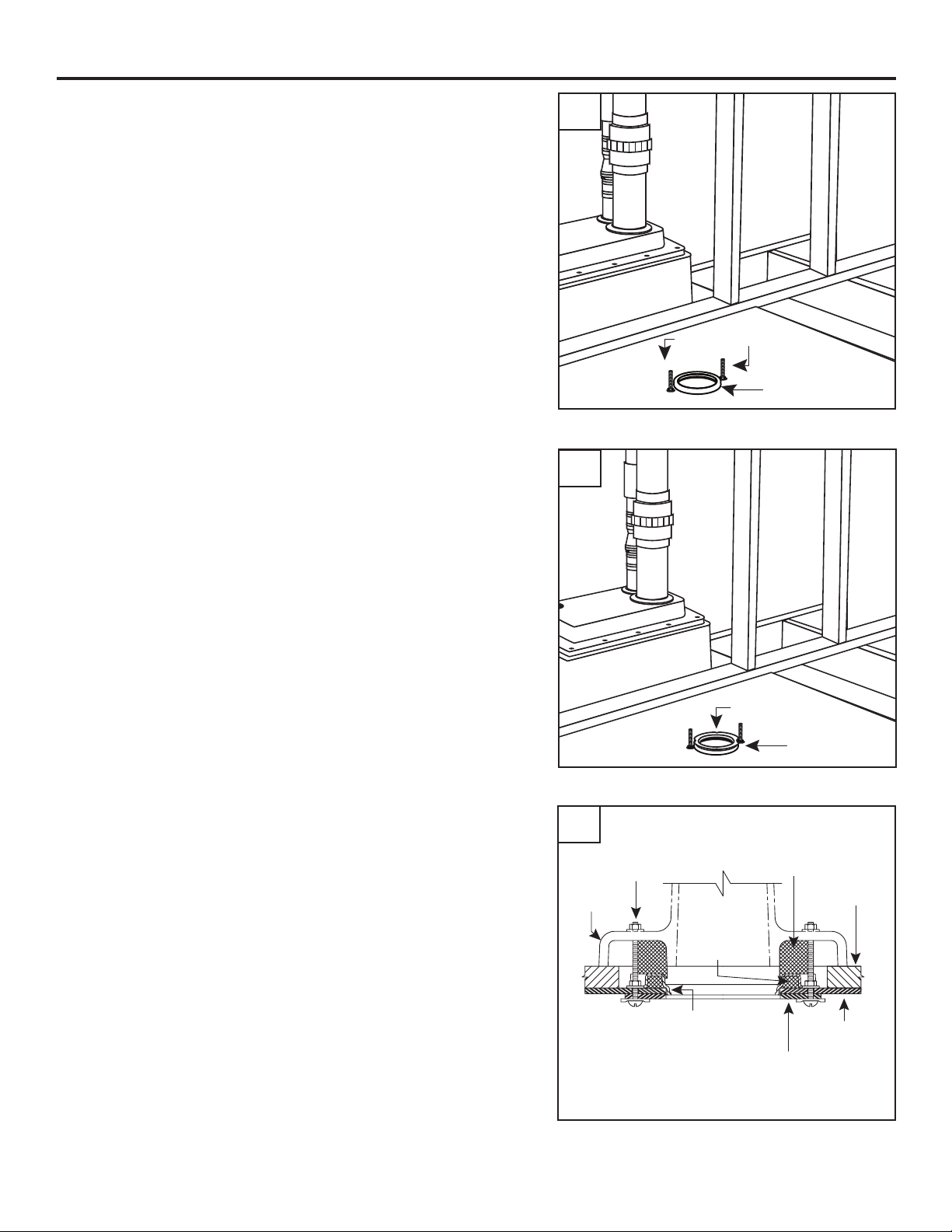
INSTALLATION OF TOILET - HIDDEN INSTALLATION
2. Firmly press wax toilet bowl ring inside the 3 in. bolts
against the top surface of the pump system.
3. Place plastic locator ring (included) on tank system and
rmly press into place until wax has completely lled
the ring. This can be checked by looking through the
four air holes on the locator ring.
2
3 in. Bolts
1st Wax Ring
3
4. Place the second wax ring (included) over the toilet
and install toilet. Lock in place using the 3 in. pan
head bolts, washer and nuts from the hardware kit.
4
3 in. Pan
Head Bolt
Toilet
Locator Ring
1st Wax
Ring
Plastic
Locator Ring
1st Wax Ring
2nd Wax
Ring
Sub Floor
Tank
Cast Iron Toilet
Stabilizer Plate
(pre-installed)
12
Page 13

INSTALLATION OF TOILET - HIDDEN INSTALLATION
5. Connect water line to toilet, fill tank and test pump
system.
INSTALLATION OF ADDITIONAL FIXTURES
1. A 3 in. hole must be drilled into pump system in order to
add additional xtures. The hole can only be drilled in
the areas shown.
CAUTION: Do not drill in cross-hatched areas noted.
5
Water
Supply
7 in. Min.
1
1-1/2 in. Min.
5 in. Min.
NOTE: Use only with additional xtures normally found
in a typical bathroom. Not recommended for washing
machines, dishwashers or other equipment.
2. Attach the spotting template from page 19 to the
desired location on pump system and center the punch
hole as shown on the template.
NOTE: Pump system is preassembled with pump
inside tank. Use caution when drilling into tank. Be sure
to remove any drilled plastic material from tank when
drilling is complete.
Do not drill in
Cross-hatched areas
of tank
2
7 in. Min.
2 in. Min.
6 in. Min.
Center line point
for 3 in. hole saw.
3 in. Dia.
Cut Template
Along This Line.
13
Page 14

INSTALLATION OF ADDITIONAL FIXTURES
3. Insert 2 in. pipe seal (included) into the 3 in. hole drilled
in Step 2. Lubricate the inside diameter of the seal with
soapy water to make it easier to insert pipe.
NOTE: Pipe installed in this 2” seal must be supported
vertically.
4. Insert approximately 3/4 in. of pipe through seal into
the tank.
NOTE: The bottom of the 3 in. hole drilled in Step 2
must be a minimum of 5 or 6 in. above the base of the
tank, depending on where the hole is drilled.
See Figures 5, 6, 7 and 8 for typical installations.
3
Do not drill in
Cross-hatched areas
of tank
4
1-1/2 in. Min.
5 in. Min.
Do not drill in
Cross-hatched areas
of tank
7 in. Min.
7 in. Min.
3 in. hole
2 in.
Pipe Seal
2 in. Min.
6 in. Min.
14
Page 15

INSTALLATION OF ADDITIONAL FIXTURES
5
Typical installation with raised tub, lavatory, vent & discharge
CAUTION: Do not drive any nails in area of tank.
Vent
Vent
4 in.
Min.
NOTE: 1) All vents and discharge piping must be installed according to local codes.
2) Wall board removed for clarity to show piping.
Vent
Gate
Valve
Discharge
GFCI
Union
by Others
Back
Flow
Device
SK1615
Alternate installation with special oor mounted raised bottom tub, lavatory, vent & discharge
6
8 Ft. Ceiling
7 Ft. Ceiling
Subfloor
3/4 in. Thick
Minimum
2x6
Floor
Joists
CAUTION: Do not drive any nails in area of tank.
GFCI
Vent
3 in.
Min.
NOTE: 1) All vents and discharge piping must be installed according to local codes.
2) Wall board removed for clarity to show piping.
3) To install a shower in place of a tub, raise the shower stall to provide a gravity drain
to the system tank and connect as shown in the diagram above.
Vent
Union
by
Others
Discharge
Shut-off Valve
by Others
Back
Flow
Device
Vent
SK1616
15
Page 16

INSTALLATION OF ADDITIONAL FIXTURES
Alternate installation with raised tub, lavatory, vent & discharge
7
8 Ft. Ceiling
7 Ft. Ceiling
Vent
Subfloor
3/4 in. Thick
Minimum
2 x 4
studs
2x6
Floor
Joists
NOTE: 1) All vents and discharge piping must be installed according to local codes.
2) Wall board removed for clarity to show piping.
GFCI
CAUTION: Do not drive any nails in area of tank.
4 in.
Min.
Vent
GFCI
Vent
Union
by
Others
Discharge
Shut-off Valve
by Others
Back
Flow
Device
SK1617
Alternate installation with special oor mounted raised bottom tub, lavatory, vent & discharge
8
8 Ft. Ceiling
7 Ft. Ceiling
Subfloor
3/4 in. Thick
Minimum
2x6
Floor
Joists
CAUTION: Do not drive any nails in area of tank.
Vent
3 in.
Min.
Discharge
Union
by
Others
Vent
Shut-off Valve
by Others
GFCI
Back
Flow
Device
Vent
NOTE: 1) All vents and discharge piping must be installed according to local codes.
2) Wall board removed for clarity to show piping.
16
SK1618
Page 17

REPLACEMENT PARTS
For replacement parts, call our customer service department at 1-800-742-5044, 7:30 a.m. - 5 p.m.,
EST, Monday - Friday.
PART DESCRIPTION PART #
A Replacement pump and switch 1101RP
B 2 in. Tank Seal KH85
C 2 in. Check Valve 006817
A
C
B
17
Page 18

TROUBLESHOOTING
Problem Possible Cause Corrective Action
Pump will not
start or run.
Pump starts too
soon.
Water level
exceeds 4-1/2
in. before pump
turns on.
Pump will not
shut off.
Pump operates
but delivers little
or no water.
Pump runs
too long
before water is
pumped.
Low voltage, blown fuse open circuit. Have a qualied electrician check fuse
and circuit.
Impeller bound. Contact an Authorized Service Station.
Motor or wiring shorted. Contact an Authorized Service Station.
Faulty or stuck oat switch Remove lid and check oat
Float “ON” point is adjusted too low. Raise the top oat stop. Make sure the
oat is between the two stops. Refer to
Testing Pump/Tank Section.
Float “ON” point adjusted to high. Lower the top oat stop. Make sure the
oat is between the two stops.
Debris under oat. Remove debris from around oat.
Faulty oat switch. Contact an Authorized Service Station.
Float “Off” point adjusted too low. Raise the bottom oat stop. Make sure
the oat is between the two stops. Refer
to Testing Section.
Debris around intake. Clean area around intake.
Blockage in discharge pipe. Remove pipe and ush out debris.
Low or incorrect voltage. Have a qualied electrician check house
wiring.
Damaged Impeller. Contact an Authorized Service Station.
Incorrect oat adjustment Make sure the oat is between the two
stops. Refer to Testing Section.
Pump is air locked. Make sure vent hole on discharge pipe
is clear.
Vertical lift too high. Change discharge piping or contact
tech. service.
Pump is air locked. Make sure vent hole on discharge pipe
is clear.
Water level too low. Clear debris from around bafe. Make
sure the oat is between the two stops.
Refer to Testing Section.
18
Page 19

SPOTTING TEMPLATE
Hole must be round. Use 3" hole saw.
Hole sizes greater than 3.040" can create leaks.
Center line point
for 3 in. hole saw.
3 in. Dia.
Cut Template
Along This Line.
SK1279
19
Page 20

STAR
®
FW1591
0113
Supersedes NEW
SISTEMA COMPLEMENTARIO
PARA EL BAÑO
¡
ALTO!
MODELO #
Patente No. 5,038,418
S1101
En caso de piezas faltantes o dañadas, o asistencia técnica, llame al
1-800-742-5044
antes de devolver el producto
Para obtener la bomba de repuesto, pida la 1102RP o consulte la Lista completa
de piezas de reparación en la página S17.
ADJUNTE SU RECIBO AQUÍ
Fecha de compra
S1
Page 21

ÍNDICE
Información de seguridad .............................................................................................................. S2
Contenido del paquete .................................................................................................................. S4
Preparación ................................................................................................................................... S5
Usos generales de la bomba ......................................................................................................... S5
Dimensiones .................................................................................................................................. S6
Ubicación del sistema de bomba................................................................................................... S6
Ubicación de los pernos ................................................................................................................ S7
Operación de prueba ..................................................................................................................... S8
Conectar a la plomería .................................................................................................................. S9
Instalación del inodoro: instalación expuesta ...............................................................................S11
Instalación del inodoro: instalación oculta ....................................................................................S11
Ensambles adicionales ................................................................................................................ S13
ezas de repuesto ......................................................................................................................... S17
Solución de problemas ................................................................................................................ S18
Plantilla de ubicación ................................................................................................................... S19
INFORMACIÓN DE SEGURIDAD
Lea y comprenda completamente este manual antes de intentar ensamblar, usar o instalar el
producto.
Revise todos los materiales antes de su instalación. Si faltan piezas o estas están dañadas, llame al
1-800-742-5044 antes de volver a la tienda.
PELIGRO DE DESCARGA ELÉCTRICA.
Siempre desconecte la fuente de alimentación antes de llevar a cabo cualquier trabajo en el motor o cerca
de este, o en su carga conectada. Si el punto de desconexión de la alimentación está fuera de la vista,
asegúrelo en la posición abierta y etiquételo para evitar una aplicación de alimentación inesperada. El
incumplimiento de dicho paso podría provocar una descarga eléctrica fatal.
PELIGRO DE DESCARGA ELÉCTRICA.
No manipule la bomba con las manos húmedas ni cuando esté parado en el agua, ya que podría ocurrir
una descarga eléctrica fatal. SIN IMPORTAR EL MOTIVO, desconecte la alimentación principal antes de
manipular la unidad.
RIESGO DE DESCARGA ELÉCTRICA.
No se ha verificado el uso de estas bombas en piscinas.
Page 22

INFORMACIÓN DE SEGURIDAD
ALERTA DE DESCARGA ELÉCTRICA.
Para reducir el riesgo de descargas eléctricas, instale solo a un tomacorriente protegido por un interruptor
de circuito de falla de puesta a tierra (GFCI, por sus siglas en inglés). Asegúrese de que el receptáculo de
falla de puesta a tierra esté al alcance del cable de suministro de electricidad de la bomba. NO UTILICE UNA
EXTENSIÓN ELÉCTRICA.
ALERTA DE DESCARGA ELÉCTRICA.
Siga todos los códigos locales eléctricos y de seguridad, además del Código nacional de electricidad (NEC, por sus siglas
en inglés) y la ley de la Administración de Salud y Seguridad Ocupacional (OSHA, por sus siglas en inglés).
ALERTA DE DESCARGA ELÉCTRICA.
No pliegue el cable de alimentación ni permita que entre en contacto con aceite, grasa, superficies calientes, sustancias
químicas u objetos afilados. Reemplace inmediatamente los cables dañados o desgastados.
ALERTA DE DESCARGA ELÉCTRICA.
Como medida de seguridad, se debe examinar cada tomacorriente para comprobar que cuenta con puesta a tierra con un
analizador de circuitos con calificación de Underwriters Laboratory que indicará si los conductores de alimentación, neutro
y de puesta a tierra están correctamente conectados en el tomacorriente. Si no lo están, póngase en contacto con un
electricista calificado.
ALERTA DE DESCARGA ELÉCTRICA.
Estas bombas se suministran con un enchufe de 3 clavijas con puesta a tierra para ayudar a protegerlo contra la
posibilidad de descargas eléctricas. NO RETIRE LA CLAVIJA DE PUESTA A TIERRA BAJO NINGUNA CIRCUNSTANCIA.
ALERTA DE DESCARGA ELÉCTRICA.
Asegúrese de que el circuito de suministro eléctrico de la bomba esté equipado con fusibles o interruptores de circuito de
la capacidad adecuada. Se recomienda un circuito de derivación aparte, de tamaño acorde al Código eléctrico nacional
para la corriente que se muestra en la placa de datos de la bomba.
ALERTA DE PRODUCTO QUÍMICO.
Este producto contiene sustancias químicas reconocidas por el estado de California como causantes de cáncer y defectos
congénitos u otros daños en el aparato reproductivo.
PUEDE PROVOCAR DAÑO AL PRODUCTO
Asegúrese de que la fuente de alimentación cumpla los requisitos de su equipo.
PUEDE PROVOCAR DAÑO AL PRODUCTO
La temperatura máxima del agua de funcionamiento continuo para bombas de modelo estándar no debe exceder los
54 °C (130 °F).
PUEDE PROVOCAR DAÑO AL PRODUCTO
No utilice dispositivos automáticos de ventilación de plomería como “Pro-Vent”. Algunos estados exigen que estos
productos sean instalados por un plomero certificado.
• NOTA: Las bombas con la marca “UL” y con la marca “US” se prueban para cumplir los estándares de UL
UL778. Las bombas con certi cación CSA cumplen con el estándar CSA C22.2 No. 108. (CUS.)
• No use un sello de cera que incluya una brida que se extiende por el tanque. Si se instala un piso sobre el
tanque, use el kit para sello extensor de brida del piso incluido con el sistema.
• Para la instalación por debajo de la línea del piso original, llame al 1-800-742-5044.
S3
Page 23

CONTENIDO DEL PAQUETE
Pieza Descripción Cantidad
A Preensamblada 1
Sello de tubería de 2 pulg
B
C Válvula de control de 2 pulg 1
D
E Anillo de cera 2
F Anillo de ubicación 1
* Kit de aditamentos 1
*No se muestra
para un agujero de 3 pulg 2
Sello de tubería de 3 pulg
para un agujero de 4 pulg 1
C
E
A
D
F
B
ESPECIFICACIONES
RENDIMIENTO
Número de
Modelo
S1101 .4 1 115
NOTA: Asegúrese de que la instalación tenga un cabezal vertical de un mínimo de 5 pies. El
máximo recomendado para un cabezal vertical es de 13 pies.
HP Fase Voltios
Pies de
cabezal
5 73
15 19
Flujo (GPM)
Cabezal de
cierre (pies)
17.5 2 pulg10 39
Tamaño de
descarga
Page 24

PREPARACIÓN
Antes de comenzar a instalar el producto, asegúrese de tener todas las piezas. Compárelas con la
lista del contenido del paquete. No intente ensamblar el producto si falta alguna pieza o si estas están
dañadas.
Tiempo estimado de instalación: 5 horas para una instalación no oculta o ensambles adicionales.
Herramientas necesarias para el ensamblaje (no se incluyen): Cinta métrica, cinta para tuberías,
sierra de mano, destornillador de cabeza plana, sistema de pegamento PVC de 2 pasos (cebado y
sellado), cemento hidráulico u otro material
Piezas necesarias para el ensamblaje (no se incluyen): Unión o acoplamiento de goma de 2 pulg,
se requieren conectores y tubos de PVC de 2 pulg y 3 pulg para completar la instalación, válvula de
cierre según lo requieran los códigos.
USOS GENERALES DE LA BOMBA
Este sistema de bomba puede utilizarse en las siguientes instalaciones:
1. Instalación expuesta (no se utiliza subsuelo).
2. Instalación oculta (se instala un subsuelo sobre la
unidad).
1
2
S5
Page 25

DIMENSIONES
Todas las dimensiones
están expresadas en pulg.
20-1/2
12-1/4
24-1/2
12-1/4
UBICACIÓN DEL SISTEMA DE BOMBA
NOTA: Si se utilizará una instalación empotrada, ubique
la cámara de la bomba en un área que permita el
acceso a la bomba y el interruptor.
13-1/2
17
5-1/2
14-1/8
42-3/16
13-1/4
IL1653
1
1. Seleccione una ubicación de acceso fácil para las
tuberías de descarga y ventilación existentes.
2. Nivele el tanque hasta 1/8 de pulg de largo y ancho.
Para nivelar, use cemento hidráulico o un material
similar.
PRECAUCIÓN: No use calzas de madera para nivelar
el tanque.
PRECAUCIÓN: Asegúrese de que clavos, tornillos u
otros objetos losos no perforen el tanque.
2
Nivele
hasta 1/8
de pulg.
Page 26

UBICACIÓN DE LOS PERNOS
1. Determine como colocará el inodoro en el sistema
de bomba. Esto determina la ubicación de los pernos
largos en el paso 2.
Nota: El sistema de bomba se envía preensamblado
con la posición de instalación hacia delante.
2. Si se desea una instalación lateral, tome nota de la
posición de los pernos de 2 pulg y retire los cuatro
pernos alrededor del agujero de entrada del inodoro
en el tanque.
Gire la ubicación de cada perno en 90 grados
alrededor del agujero de instalación del inodoro
pretaladrado y vuelva a instalarlo. Torque los tornillos
hasta 2,88 a 3,46 kgf-m. NO torque demasiado los
tornillos.
1
Posición lateralPosición hacia delante
O
2
Ubicación del
perno de 2 pulg
para el inodoro
en posición de
montaje
hacia delante
Ubicación del
perno de 2
pulg para el
inodoro en
posición de
montaje lateral
3. Si se instala un subsuelo, retire los pernos de 2 pulg
que se encuentran alrededor del agujero de entrada
del inodoro en el tanque y reemplácelos con los
pernos de 3 pulg del kit de aditamentos.
S7
3
Page 27

OPERACIÓN DE PRUEBA
1. NOTA: El nivel de encendido y apagado del
interruptor del otador ha sido preajustado, sin
embargo, debe veri carse revisando la entrada del
inodoro.
Conecte temporalmente la tubería de descarga de la
bomba a la tubería de desagüe doméstica y enchufe
la bomba
2. Llene el tanque con 4 pulg de agua. Asegúrese de que
la bomba no se encienda.
1
Tomacorrientes
con interruptor
de circuito de
falla de
puesta a tierra
Entrada
del inodoro
2
Conexión
temporal al
desagüe
doméstico
3. Agregue 1,27 cm adicional de agua al tanque. La
bomba debe encenderse (“ON”) cuando el nivel de
agua alcance 4-1/2 pulg. Si el nivel de encendido
es el correcto, desenchufe la bomba, desconecte
temporalmente la tubería de desagüe y continúe con la
siguiente sección.
Si el nivel de encendido no es el correcto, consulte
Solución de problemas en la página S18.
10,16 cm
de agua
3
11.43 cm
de agua
Page 28

Válvula
CONECTAR A LA PLOMERÍA
1. Instale la tubería de descarga rígida de 2 pulg (no se
incluye) de acuerdo con los códigos locales, regionales
y estatales. Use un sistema de adhesivo PVC de 2
pasos (no se incluye) para unir la tubería y cualquier
conector necesario.
PRECAUCIÓN: No utilice una tubería de desagüe
más pequeña que la tubería de desagüe preinstalada
en el sistema.
2. Instale una válvula de control de 2 pulg (se incluye) en
la tubería de desagüe para evitar el re ujo.
PRECAUCIÓN: Asegúrese de que las echas de ujo
en la válvula de control apunten hacia arriba.
1
2
Tubería de
descarga
Válvula
de control
3. Instale una válvula de cierre de 2 pulg (no se incluye)
sobre la válvula de control en la tubería de desagüe.
S9
3
de
cierre
Page 29

13 pies
CONECTAR A LA PLOMERÍA
4. Conecte la tubería de desagüe en la tubería de desagüe
principal que va hacia el desagüe o el tanque séptico.
NOTA: Asegúrese de que la tubería de desagüe tenga
un cabezal vertical de mínimo 5 pies y máximo 13 pies.
5. Conecte la tubería de ventilación rígida de 3 pulg
(no se incluye) de acuerdo con los códigos locales,
regionales y estatales. Incluya una unión en la línea
para facilitar el mantenimiento.
NOTA: Veri que con la autoridad de código local si
desea reducir el tamaño de la tubería de ventilación.
PRECAUCIÓN: No utilice ventilación mecánica de
ningún tipo.
4
5
Tubería de
desagüe
principal
Tubería de
desagüe
principal
A la
ventilación
de techo
Unión
5 pies
mín.
máx.
Page 30

Suministro
INSTALACIÓN DEL INODORO: INSTALACIÓN EXPUESTA
Instalación expuesta (no se utiliza subsuelo)
1. Instale 1 anillo de cera para taza de inodoro (se incluye)
y el inodoro como se describe en la caja del anillo para
inodoro.
2. Conecte la tubería de agua al inodoro. Llene el tanque y
pruebe el sistema de bomba.
1
2
de agua
INSTALACIÓN DEL INODORO: INSTALACIÓN OCULTA
1. Corte un agujero de 6-1/2 pulg en el subsuelo,
centrado en la abertura del tanque del inodoro en el
sistema de bomba.
NOTA: Cuando utilice un subsuelo, los pernos de 2
pulg preinstalados en el tanque deben reemplazarse
con los pernos de 3 pulg incluidos en el kit de
aditamentos.
S11
1
Agujero de
6-1/2 pulg
de diámetro
Page 31

Primer anillo
de cera
de cera
INSTALACIÓN DEL INODORO: INSTALACIÓN OCULTA
2. Presione rmemente el anillo para taza de inodoro
dentro de los pernos de 3 pulg contra la super cie
superior del sistema de bomba.
3. Coloque el anillo de ubicación de plástico (se incluye)
en el sistema de tanque y presione rmemente en el
lugar hasta que la cera llene por completo el anillo.
Esto puede veri carse a través de los cuatro agujeros
de aire en el anillo de ubicación.
2
Pernos de 3 pulg
Primer anillo
3
4. Coloque el segundo anillo de cera (se incluye) sobre
el inodoro e instale el inodoro. Asegúrelo en su lugar
con los pernos de cabeza plana de 3 pulg, arandelas
y tuercas del kit de aditamentos.
4
Perno de cabeza
plana de 3 pulg
Inodoro
Anillo de ubicación
de plástico
Anillo de
ubicación
Segundo
anillo de cera
Subsuelo
Primer anillo
de cera
Tanque
Placa estabilizadora
de inodoro de hierro
forjado (preinstalada)
Page 32

Mínimo de
INSTALACIÓN DEL INODORO: INSTALACIÓN OCULTA
5. Conecte la tubería de agua al inodoro, llene el tanque y
pruebe el sistema de bomba.
ENSAMBLES ADICIONALES
1. Debe taladrarse un agujero de 3 pulg en el sistema
de bomba para agregar ensambles adicionales. El
agujero solo puede taladrarse en las áreas que se
muestran.
PRECAUCIÓN: No taladre en las áreas marcadas con
líneas diagonales.
NOTA: Use solo ensambles adicionales que se
encuentran normalmente en un baño típico. No
se recomienda para lavadoras, lavaplatos u otros
equipos.
5
1
Mínimo de
3,81 cm
Mínimo
de
12,7 cm
No taladre en las áreas del
tanque marcadas con
líneas diagonales
Mínimo de 17,78 cm
Mínimo de 17,78 cm
Suministro
de agua
2 pulg
Mínimo
de
15,24 cm
2. Adjunte la plantilla de ubicación de la página 19 a la
ubicación deseada en el sistema de bomba y centre el
agujero perforado como se muestra en la plantilla.
NOTA: El sistema de bomba está preensamblado con
el tanque de la bomba dentro. Tenga cuidado cuando
taladre la parte interna del tanque. Una vez nalizada
la perforación, retire cualquier material de plástico
taladrado del tanque.
S13
2
Punto central para la
sierra de perforación
de 3 pulg
3 pulg de
diámetro
Corte la plantilla
por esta línea.
Page 33

Mínimo de
ENSAMBLES ADICIONALES
3. Inserte un sello de la tubería de 2 pulg (se incluye) en
el agujero de 3 pulg taladrado en el Paso 2. Lubrique
el diámetro interno del sello con agua y jabón para
facilitar la inserción de la tubería.
NOTA: La tubería instalada en este sello de 2 pulg
debe tener un soporte vertical.
4. Inserte aproximadamente 3/4 de pulg de la tubería a
través del sello al tanque.
NOTA: La parte inferior del agujero de 3 pulg
taladrado en el Paso 2 debe tener un mínimo de
12,7 cm o 15,24 cm por sobre la base del tanque,
dependiendo del lugar donde se taladre el agujero.
Consulte las instalaciones típicas en las Figuras 5, 6,
7 y 8.
3
No taladre en las áreas
del tanque marcadas
con líneas diagonales
4
Mínimo de
3,81 cm
Mínimo
de
12,7 cm
No taladre en las áreas del
tanque marcadas con
líneas diagonales
Mínimo de 17,78 cm
Mínimo de 17,78 cm
Agujero de
3 pulg
Sello de la
tubería de
2 pulg
2 pulg
Mínimo
de
15,24 cm
Page 34

ENSAMBLES ADICIONALES
5
Instalación típica con bañera, lavamanos, ventilación y desagüe elevados
PRECAUCIÓN: No atornille clavos en el área del tanque.
Ventilación
Ventilación
Ventilación
Válvula
de compuerta
Mínimo
de
10,16 cm
NOTA: 1) Todas las tuberías de ventilación y desagüe deben instalarse acuerdo con los
códigos locales, regionales y estatales.
2) Se retiró la tabla para pared para claridad al mostrar la tubería.
Descarga
GFCI
Unión
de otros
Dispositivo
de reflujo
SK1615
Instalación alternativa con piso especial montado para elevar bañera, lavamanos, ventilación
6
y desagüe inferiores
Techo de 2,44 m
Techo de 2,13 m
Grosor mínimo
del subsuelo
de
19,05 mm
2 x 6
viguetas
de piso
PRECAUCIÓN: No atornille clavos en el área del tanque.
Ventilación
Mínimo
de
7,62 cm
NOTA: 1) Todas las tuberías de ventilación y desagüe deben instalarse acuerdo con los
códigos locales, regionales y estatales.
2) Se retiró la tabla para pared para claridad al mostrar la tubería.
3) Para instalar una ducha en lugar de una bañera, levante el compartimiento para
ducha para proporcionar un desagüe de gravedad al tanque del sistema
GFCI
Ventilación
Unión
de
otros
Descarga
Válvula de
cierre de
otros
Disposit vo
de reflujo
Ventilación
SK1616
S15
Page 35

ENSAMBLES ADICIONALES
Instalación alternativa con bañera, lavamanos, ventilación y desagüe elevados
7
Techo de 2,44 m
Techo de 2,13 m
GFCI
PRECAUCIÓN: No atornille clavos en el área del tanque.
Ventilación
Grosor mínimo
del subsuelo de
19,05 mm
Montantes
de 2 x 4
2 x 6
viguetas
de piso
NOTA: 1) Todas las tuberías de ventilación y desagüe deben instalarse acuerdo con los
códigos locales, regionales y estatales.
2) Se retiró la tabla para pared para claridad al mostrar la tubería
Instalación alternativa con piso especial montado para elevar bañera, lavamanos, ventilación
8
Mínimo
10,16 cm
Ventilación
GFCI
Ventilación
Unión
de
otros
Descarga
Válvula de
cierre de
otros
Dispositivo
de reflujo
y desagüe inferiores
Techo de 2,44 m
Techo de 2,13 m
SK1617
Grosor mínimo
del subsuelo
de
19,05 mm
2 x 6
viguetas
de piso
PRECAUCIÓN: No atornille clavos en el área del tanque.
Descarga
Ventilación
NOTA: 1) Todas las tuberías de ventilación y desagüe deben instalarse acuerdo con los
códigos locales, regionales y estatales.
2) Se retiró la tabla para pared para claridad al mostrar la tubería.
Mínimo
de
7,62 cm
Ventilación
Unión
de
otros
Válvula de
cierre de otros
GFCI
Dispositivo
de reflujo
Ventilación
SK1618
Page 36

PIEZAS DE REPUESTO
Para obtener piezas de repuesto, llame a nuestro Departamento de Servicio al Cliente
al 1-800-742-5044, de lunes a viernes de 7:30 a.m. a 5:00 p.m., hora estándar del Este.
PIEZA DESCRIPCIÓN PIEZA #
A Bomba e interruptor de reemplazo 1101RP
B Sello de tanque de 2 pulg KH85
C Válvula de control de 2 pulg 006817
A
C
B
S17
Page 37

SOLUCIÓN DE PROBLEMAS
Problema Causa posible Acción correctiva
La bomba no
enciende ni
funciona.
La bomba
se enciende
demasiado
pronto.
El nivel del
agua excede
11,43 cm antes
de encender la
bomba.
La bomba no se
cierra.
La bomba
funciona pero
sale muy poca o
nada de agua.
La bomba trabaja
mucho antes de
bombear el agua.
Voltaje bajo, fusible fundido, circuito
abierto.
El impulsor se salta. Póngase en contacto con una estación de
Se produjo cortocircuito en el motor o
cableado.
El interruptor de otador está defectuoso o
atascado
El punto de encendido (“ON”) del otador
está ajustado en una posición demasiado
baja.
El punto de encendido (“ON”) del otador
está ajustado en una posición demasiado
alta.
Hay desechos bajo el otador. Retire todos los desechos alrededor del
El interruptor del otador está defectuoso. Póngase en contacto con una estación de
El punto de apagado (“Off”) del otador
está ajustado en una posición demasiado
baja.
Hay desechos alrededor de la entrada. Limpie el área alrededor de la entrada.
Hay un bloqueo en la tubería de descarga. Retire la tubería y enjuague los desechos.
El voltaje es incorrecto o bajo. Pídale a un electricista cali cado que revise
El impulsor está dañado. Póngase en contacto con una estación de
El ajuste del otador es incorrecto Asegúrese de que el otador quede entre
La bomba está bloqueada con aire. Asegúrese de que el agujero de ventilación
La elevación vertical es demasiado alta. Cambie la tubería de desagüe o póngase
La bomba está bloqueada con aire. Asegúrese de que el agujero de ventilación
El nivel de agua es demasiado bajo. Limpie los desechos alrededor del de ector.
Pídale a un electricista cali cado que revise
el fusible y el circuito.
servicio autorizada.
Póngase en contacto con una estación de
servicio autorizada.
Retire la tapa y revise el otador
Levante el tope superior del otador.
Asegúrese de que el otador quede entre
los dos topes. Consulte la sección Prueba
de la bomba/el tanque.
Baje el tope superior del otador. Asegúrese
de que el otador quede entre los dos
topes.
otador.
servicio autorizada.
Levante el tope inferior del otador.
Asegúrese de que el otador quede entre
los dos topes. Consulte la sección Prueba.
el cableado doméstico.
servicio autorizada.
los dos topes. Consulte la sección Prueba.
en la tubería de desagüe esté despejado.
en contacto con el servicio técnico.
en la tubería de desagüe esté despejado.
Asegúrese de que el otador quede entre
los dos topes. Consulte la sección Prueba.
Page 38

PLANTILLA DE UBICACIÓN
El agujero debe ser redondo. Use una
perforación del agujero de 3 pulg.
Los agujeros de más de 3,040 pulg pueden
provocar ltraciones.
Punto central para la
sierra de perforación
de 3 pulg
3 pulg de
diámetro
Corte la plantilla
por esta línea.
SK1279
S19
 Loading...