

Page 1
INSTALLATION INSTRUCTIONS
Supersedes
Fully Automatic Water Filters
SW0015
0310
0201
INSTALLATION INFORMATION
Model No. ______________________________________
Unit Date Code __________________________________
Date Installed ____________________________________
WATER ANALYSIS RECORD
Hardness _____ GPG Sulfur _____ PPM
Iron _____ PPM pH _____
Manganese _____ PPM Tannins _____ PPM
Turbidity _____ FTU
Other:
Other Water Treatment Equipment Installed:
Installed By:
AUTOMATIC MODELS
07AF-10
134841
95 North Oak Street • Kendallville, IN 46755
For Service Call:
1
Page 2
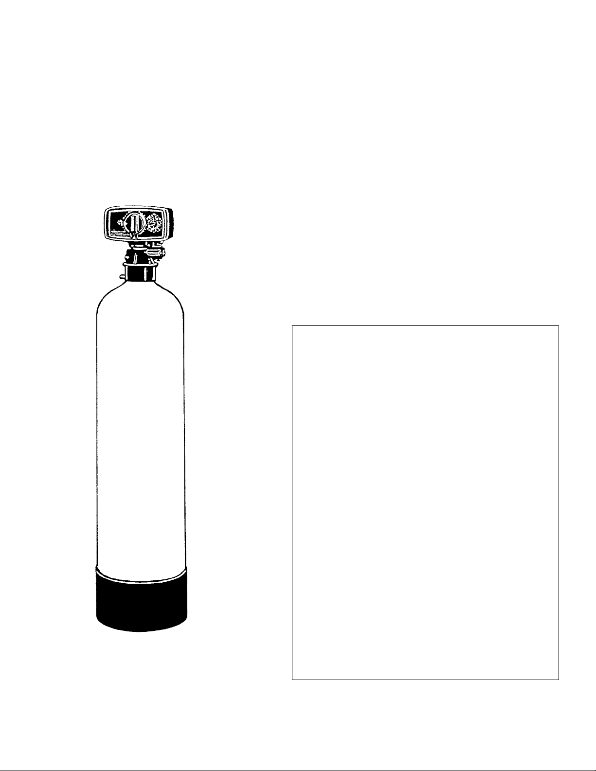
WATER FILTER SPECIFICATIONS (Figure 1)
IL0635
APPLICATION FILTER BED
Neutralizing Acid Water, 6.0 to 7.0 pH 1 cu. ft. Neutralizing Mineral and 20 lbs.* “D” Gravel (Underbed)
Taste and Odor Removal, Wide Application 1 cu. ft. Activated Carbon and 20 lbs.* “D” Gravel (Underbed)
Remove up to 10 PPM Iron 1 cu. ft. Birm and 20 lbs.* “D” Gravel (Underbed)
Remove fine suspended matter and turbidity
1 cu. ft. Filter-Ag and 20 lbs.* “D” Gravel (Underbed)
up to 125 PPM
*Gravel installed in mineral tank at factory
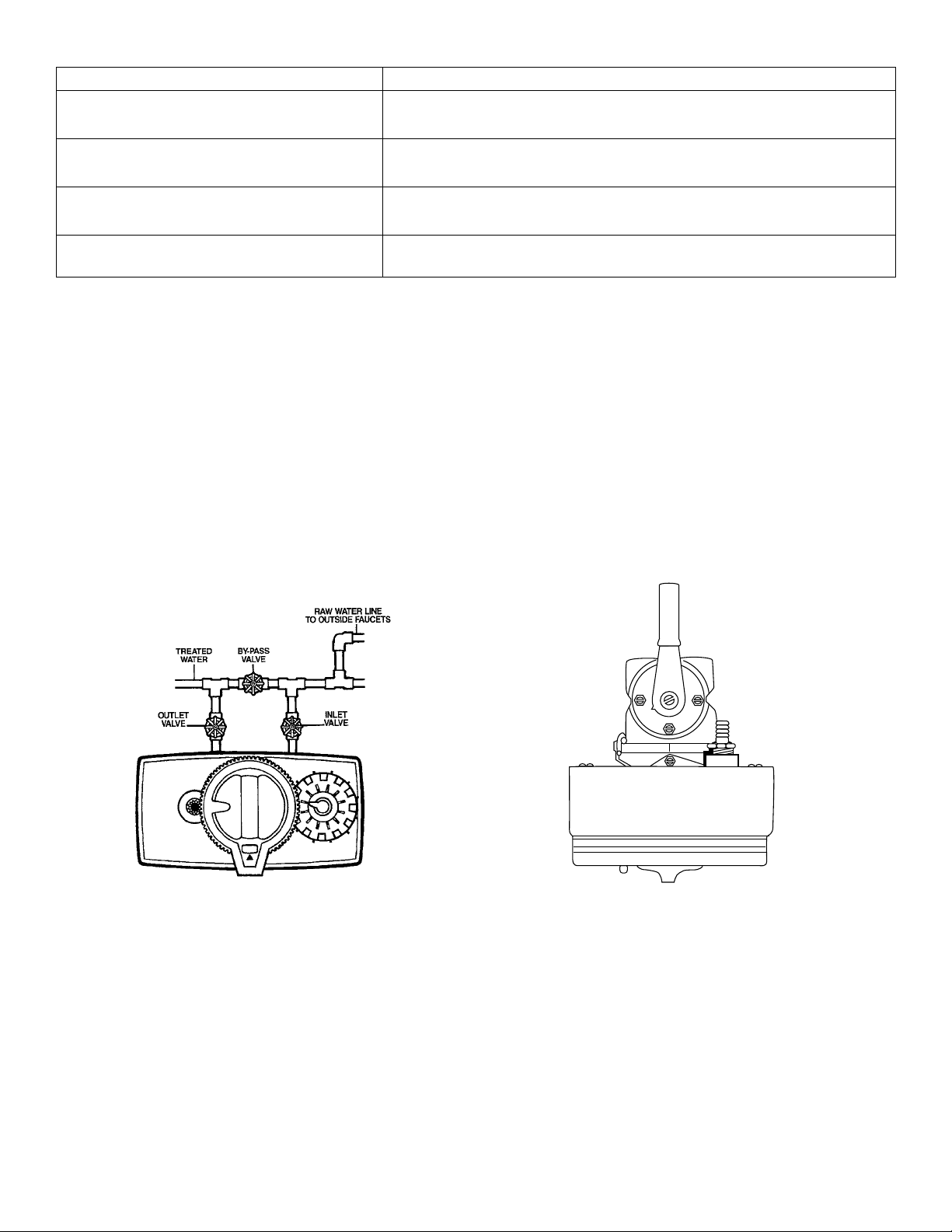
INSTALLATION ILLUSTRATIONS (Figure 2)
Outlet Inlet
By-Pass
Valve
Drain
Connection
3-VALVE BY-PASS SYSTEM INCLUDED BY-PASS VALVE
2
Page 3

FILTER INSTRUCTIONS
These instructions cover fully automatic filters. Read
thoroughly before proceeding with the installation. Check to
be sure water is available in sufficient volume and pressure
to adequately backwash the equipment at the specified rate.
When higher service flow rates are required or water for
backwash is limited, two units should be installed in parallel.
Such an installation doubles the service flow rate without
increasing the backwash requirement. Naturally, they should
be set to backwash at different times - at least two hours
apart.
Filter Operation - During “Service” the water flows down
through the mineral bed and out to service lines. Collected
turbidity and sediment must be regularly removed from a
filter by reversing the flow of water through the filter and
running to drain. Called “backwashing”, and lasting 15
minutes, this process expands the mineral bed, freeing the
turbidity - which is then washed out to drain.
Normally, the units should be set to backwash twice every
12 days. Where conditions are extreme a more frequent
backwash schedule will be required to assure the
maintenance of a clean filter bed.
A 46 minute setting period follows the backwashing where
no flow to drain will be observed. Then a down flow rinse to
drain follows to purge untreated water from bottom of filter
bed and to settle the bed before returning to service.
During backwashing and rinsing, untreated water is
by-passed to the service lines so that uninterrupted water
service is maintained.
1. UNPACKING
Check packing list located on outside of tank carton against
cartons received. The large carton contains the filter tank,
main control valve and underbed gravel. Filter mineral is
available and is packaged separately.
2. LOCATION
For complete customer satisfaction, all water in the home
should be filtered with the exception of the outside faucets.
Select a location near the water service inlet and near a
floor drain. Be certain that all sides of the filter are easily
accessible for service and maintenance. On a private water
system, locate filter as shown in Diagram A. An uninterrupted
115 volt circuit must be nearby for automatic units.
3. MINERAL
The tank must be loaded with mineral after the tank has
been placed at the desired location. Remove the valve by
unscrewing from the mineral tank. Leave distributor tube in
the tank while filling. Cover top of distributor tube to prevent
mineral from entering tube while filling. Place funnel in hole.
Pour several gallons of water in the tank then pour in the
filter mineral.
The required quantity of each type of filter mineral is shown
under specifications, Figure 1. When filled, the tank should
be approximately two thirds full. As a check, measure
distance from top of filling port to the mineral bed surface.
This distance should be approximately 18 inches.
Fill tank with water by using a garden hose or several
buckets of fresh water. This will permit the filtering material
to become soaked while preparing the installation and will
prevent the control valve from being plugged with floating
mineral on initial backwash. Remove funnel and the plastic
plug from the distributor tube. Replace the valve, while
being careful to position the distributor tube into the
distributor pilot tube in the adapter.
3
Page 4

4. WATER SUPPLY CONNECTIONS
Figure 2 shows typical installations. Inlet and outlet
connections are 3/4 inch pipe size and are marked with
raised arrows on the sides of the plastic valve. Turn off main
water supply and connect the pipes, valves and fittings.
CAUTION: IF COPPER PIPING WITH
SWEAT FITTINGS IS USED, DO NOT
SWEAT DIRECTLY INTO THE IN/OUT
MANIFOLD OF FILTER VALVE OR
BY-PASS VALVE. HEAT WILL DAMAGE
RUBBER AND PLASTIC PARTS.
5. DRAIN LINE CONNECTIONS
Install 1/2” I.D. plastic pipe or tubing from the hose barb
located on right side of main control valve to an open
drain. Do not connect the drain line directly to a sewer as
this would violate sanitary codes. A 4 inch gap between
the end of the drain line and a sewer is recommended.
Keep drain line as short as possible. An overhead drain
line can be used if necessary, but should discharge below
the main control valve if possible.
CAUTION: NEVER CONNECT DRAIN LINE
INTO A DRAIN, SEWER LINE OR TRAP.
ALWAYS ALLOW AN AIR GAP BETWEEN
THE DRAIN LINE AND THE WASTE WATER
TO PREVENT THE POSSIBILITY OF
SEWAGE BEING BACK SIPHONED.
6. ELECTRICAL CONNECTIONS
AUTOMATIC CONTROL VALVE
7. SETTING THE TIME CONTROL
Time of Day - Depress the red button, disengaging the large
gear. Turn the large gear until the actual time of day appears
at the Time of Day arrow. Note “AM” and “PM” selections on
the large gear and set the time accordingly. Release the red
button, making sure the gear is engaged.
Backwash Frequency - Set the days you want regeneration
to occur by sliding tabs on the skipper wheel outward to
expose fingers. By sliding one tab, the filter will backwash
every 12 days. Slide tabs 1 and 7 to backwash every 6
days.
Other Settings - The starting time of backwash is preset for
2:00 A.M. on each day for which skipper wheel tab is slid
out. All other settings such as Backwash, Rinse, and Fast
Rinse have been preset.
8. CONTROL VALVE POSITIONS
AUTOMATIC FILTER - The automatic control valve must
be started in service position! The words “In Service” are
imprinted in the manual regeneration knob dial. Rotating the
manual knob CLOCKWISE will place the unit in the various
positions printed on the dial.
The positions printed on the dial and cycle times are as
follows:
Automatic filters are equipped with a 6 ft., 115 volt,
grounded power cord. When the plug is inserted into a
properly grounded receptacle, it will guard the user against
electrical shock if the unit insulation should fail for any
reason.
Do not plug into an outlet controlled by a wall switch or a
pull chain that could be inadvertently turned off.
DIAL READING
1. In Service
2. Regeneration
3. Rinse
4. Backwash
5. Pause
6. Rapid Rinse
7. Settle Rinse
4
CYCLE TIME
5 Min. Rinse
12 Min. Backwash
46 Min.Settling period
12 Min. Backwash
5 Min. Rinse
Page 5

9. STARTING THE UNIT
Place the control valve in the SERVICE POSITION and
follow these steps:
(a) Place the by-pass valve (valves) to SERVICE position
and allow water to flow into the mineral tank. On a
3-valve system (Figure 2) open the inlet and outlet
valves and close the by-pass valve.
(b) When the water stops flowing, open a treated water tap
until all air is released from the lines, then close the
tap.
(c) Manually index knob to the BACK WASH POSITION.
(Clockwise rotation.)
(d) Plug in the electrical cord. Set the days of backwash
desired. Set the time of day as also noted in Section 7.
On all units except carbon filters, allow the unit to
backwash 15 minutes or until the water becomes clear
at drain. This will wash out the fine material from the
mineral. Check water at drain to be certain large
quantities of mineral are not being lost. If so, return
valve to IN SERVICE position and allow mineral to soak
longer before being backwashed.
NOTE: WHEN INSTALLING A CARBON FILTER, IT IS
BEST TO ALLOW AT LEAST 3 HOURS OR
PREFERABLY OVERNIGHT FOR CARBON TO SOAK
BEFORE ATTEMPTING TO BACKWASH. TO SPEED
WETTING, OPEN THE FAUCET OF THE TREATED
SUPPLY AND ALLOW TO RUN 5 MINUTES OR
LONGER OR UNTIL WATER IS CLEAR. IF
CONSIDERABLE CARBON IS STILL BEING LOST
WHEN BACKWASHING, LEAVE IT SOAK FOR A DAY
OR TWO LONGER.
(e) Position to RAPID RINSE. The automatic valve will
automatically return to IN SERVICE after approximately
17 minutes.
13. FINAL CHECKOUT
(a) Be certain by-pass valve is closed and inlet and outlet
valves are fully open.
(b) Check electrical supply to be certain cord is connected
to an uninterrupted 115 volt outlet.
(c) Be certain warranty card is filled out and mailed in.
14. ADDITIONAL INFORMATION
(a) Carbon filter mineral must be replaced periodically to
ensure filter effectiveness. Maximum carbon life is three
years.
(b) Calcite filter mineral dissolves slowly. Therefore, it will be
necessary to add calcite to the unit from time to time.
10. BACKWASH
Units will now Backwash on a frequency as established in
Step 7 “Setting the Time Control.”
11. EXTRA BACKWASH
Valve can be manually regenerated by turning the control
knob to the Backwash position. The unit will automatically
continue through the regeneration cycle and return to the
SERVICE position when regeneration is complete.
12. TO SKIP BACKWASH
For vacations or extended periods of absence, the timer
cord plug can be pulled out of receptacle. Upon return, plug
in timer, reset the time of day (Section 7-A) and backwashing
will resume as normal.
5
 Loading...