

Page 1
Rolling Tortilla Warmer
Owner’s Manual
Models
RTW14E and RTW20E [patent pending]
This manual includes material related to installation,
use , cleaning, and care. Exploded view[s], as well
as any available parts list[s] and wiring diagram[s]
pertaining to the unit[s] covered by this manual are
also included.
This manual must be read and understood by all
persons using or installing this appliance. Contact
your Star dealer if you have any questions concerning
installation, use, or maintenance of this equipment.
DO NOT DISCARD THIS MANUAL.
RTW14E
2M-Z19213 - Rev D - 06.2016
Page 2

LIMITED EQUIPMENT WARRANTY
All workmanship and material in Star products have a one (1) year limited warranty on parts and labor in the United States and Canada unless
otherwise noted below. Such warranty is limited to the original purchaser only and shall be eff ective from the date the equipment is placed in
service. Star’s obligation under this warranty is limited to the repair of defects without charge, by the factory authorized service agency or one
of its sub-agencies. Star will not assume any responsibility for loss of revenue. Models that are considered “portable” (see below) should be
taken to the closest Star service agency, transportation prepaid. On all shipments outside the U.S.A. and Canada, see the International Warranty.
This warranty does not apply to any item that is disassembled or tampered with for any purpose other than repair by a Star-authorized service
center or the service center’s sub-agency. This warranty does not apply if damage occurs from improper installation, misuse, wrong voltage,
wrong gas or operated contrary to the Installation and operating instructions. This warranty is not valid on Conveyor Ovens unless a “start-up/
check-out” has been performed by a factory authorized technician. This warranty does not apply to “Special Products” but to regular catalog
items only. Star’s warranty on “Special Products” is six (6) months on parts and ninety (90) days on labor.
�
The warranty period for Ultra-Max Hot Plates, Griddles, and Char Broilers is (3) years parts and labor.
�
The warranty period for Star-Max Char Broilers, Griddles, Hot Plates, Fryers, and Finishing Ovens is (2) years parts and labor.
�
The warranty period for JetStar series six (6) ounce and eight (8) ounce Popcorn Poppers is two (2) years.
�
The warranty period for Chrome-Max Griddles is fi ve (5) years on the griddle surface. See detailed warranty provided with unit.
�
The warranty period for Duratec coatings is one (1) year under normal use and reasonable care. The warranty period for Staltek coatings
is fi ve (5) years under normal use and reasonable care. This warranty does not apply if damage occurs to the coating from improper cleaning
or maintenance, use of metallic utensils, abrasive cleaners or pads, or damage from any other non-food object that comes in continuous
contact with the roller coating. This warranty does not apply to the “non-stick ” properties of such materials. This warranty is not valid on
rollers purchased as replacement parts.
PARTS WARRANTY
Parts that are sold to repair out of warranty equipment are warranted for ninety (90) days. The labor to replace the part is NOT warrantied.
SERVICES AND EXPENSES NOT COVERED BY WARRANTY
• Travel time and mileage rendered beyond the 50-mile radius limit
• Mileage and travel time on “portable” equipment (see below)
• Labor to replace such items that can be replaced easily during
• a daily cleaning routine (e.g., removable kettles on fryers, knobs,
• grease drawers on griddles, etc.)
• Installation of equipment
• Cleaning of equipment
• Seasoning of griddle plates
• Voltage conversions or gas conversions
• Pilot light adjustment
• Miscellaneous adjustments
• Thermostat calibration and bypass adjustment
• Resetting of circuit breakers, safety controls, or reset buttons
• Replacement of bulbs or fuses
• Repair of da mag e crea ted dur ing tr an sit, d eliver y, or ins ta llatio n
or created by an act of God.
PORTABLE EQUIPMENT
Star will not honor service bills that include travel time and mileage charges for servicing any products considered “portable” including items
listed below. These products should be taken to the Service Agency for repair:
• Model 510FD, 510FF Fryer
• Model 526TOA Toaster Oven
• Model J4R, 4 oz. Popcorn Machine
• Model 518CMA & 526CMA Cheese Melter
• Model 12MC & 15MC & 18MCP Hot Food Merchandisers
• Model 12NCPW & 15NCPW Nacho Chip/Popcorn Warmer
• QCS/RCS series Toasters except model QCS3 & RCS3 series
• Nacho Cheese Warmers except model 11WLA series Nacho
Cheese Warmer
• Condiment Dispensers except the model HPD & SPD series
Dispenser
• Pretzel Merchandisers (model 16PD-A only)
• Hot Dog equipment except Roller Grills, Drawer Bun Warmers,
and Direct Connect series Fast Steamers.
• Specialty Food Warmers except model 130R, 11RW series, and
11WSA series
• Pizza Ovens (model PO12 only)
All:
• Pop-Up Toast ers
• Butter Dispensers
• Pastry Display Cabinets
• Nacho Chip Merchandisers
• Accessories of any kind (e.g. Sneeze Guards, Manual Pumps, etc.)
• Heat Lamps
The foregoing warranty is in lieu of any and all other warranties expressed or implied and constitutes the entire warranty.
Should you require any assistance regarding the operation or
maintenance of any Star equipment; write, phone, fax or email
our Service Department. In all correspondence mention the
model number and the serial number of your unit, as well as
the voltage or type of gas you are using.
Business hours: 8:00 a.m. to 4:30 p.m. Central Standard Time
Telephone: 314-678-6303
Fax: 314-781-2714
Email: customerservice@star-mfg.com
Website: www.star-mfg.com
i
Page 3

TABLE OF CONTENTS
Warranty i
General Information and Installation 1–2
Daily Operation 3–4
Cleaning 5
Maintenance 6
Wiring Diagram 7
Exploded Views 8–13
Parts List 14–17
Wall Mount Installation 18–19
Specifications 20
Factory Settings Adjustment 21
Page 4

NOTES
iii
Page 5

SAFETY SYMBOLS
These symbols are intended to alert the user to the
presence of important operating and maintenance
instructions in the manual accompanying the appliance.
THOROUGHLY INSPECT YOUR UNIT ON ARRIVAL
This unit has been tested for proper operation before leaving our plant to ensure delivery of your unit
in perfect condition. However, there are instances in which the unit may be damaged in transit. In the
event you discover any type of damage to your product upon receipt, you must immediately contact
the transportation company who delivered the item to you and initiate your claim with that company.
If this procedure is not followed, it may a ect the warranty status of the unit. Please record the model
number, serial number, voltage, and purchase date in the area below at the time of receipt..
Model Number
Serial Number
Voltage
Purchase Date
NOTICE
Using any part other than genuine Star factory supplied parts relieves the manufacturer of all liability.
Due to periodic changes in designs, methods, procedures, policies, and regulations, the specifications
contained in this sheet are subject to change without notice. Star reserves the right to change product
specifications and design without notice. Such revisions do not entitle the buyer to corresponding
changes, improvements, additions or replacements for previously purchased equipment. While Star
International Holdings Inc. exercises good faith e orts to provide information that is accurate, we are
not responsible for errors or omissions in information provided or conclusions reached as a result
of using the specifications. By using the information provided, the user assumes all risks in connection
with such use.
PLEASE REFER TO THE WARRANTY PAGE FOR SPECIFIC WARRANTY INFORMATION.
MAINTENANCE AND REPAIRS
Contact your local authorized service agent for service or required maintenance. Please have the
information in the above fields ready when you call to ensure a faster service.
AUTHORIZED SERVICE AGENT LISTING
Reference the listing provided with the unit or for an updated listing go to the website or call customer
service to find an agent.
Business hours: 8:00 a.m. to 4:30 p.m. Central Standard Time
Telephone: 314-678-6303
Fax: 314-781-2714
Email: customerservice@star-mfg.com
Website: www.star-mfg.com
1
2M-Z19213 Rev D - Owner's Manual for RTW Rolling Tortilla Warmer
Page 6
GENERAL SAFETY INFORMATION
This equipment is designed and sold for commercial use only, and is intended for use by personnel
trained and experienced in its operation. This is not sold for consumer use in and around the home
nor for use directly by the general public in food service locations.
Before using your new equipment, read and understand all the instructions and labels associated
with the unit prior to putting it into operation. Make sure all people associated with its use understand
the units operation and safety before they use the unit.
GENERAL INSTALLATION INFORMATION
The unit is shipped fully assembled and ready to plug into a standard outlet specified for its voltage
and amp draw. If improper electrical supply can be determined through troubleshooting, contact
a qualified electrician prior to using the unit. Removal or replacement of the power cord or plug will
void the warranty. Should you require assistance, contact your local authorized service agent for any
service or required maintenance.
Level unit using the adjustable feet under the unit [there is approximately 0.5 (1/2) inch of adjustment].
Allow enough space around the unit for adequate ventilation. It is recommended that you leave a ten
(10) inch gap on the top for cleaning if the unit is to remain stationary. The sides and back of the unit
require no additional clearance.
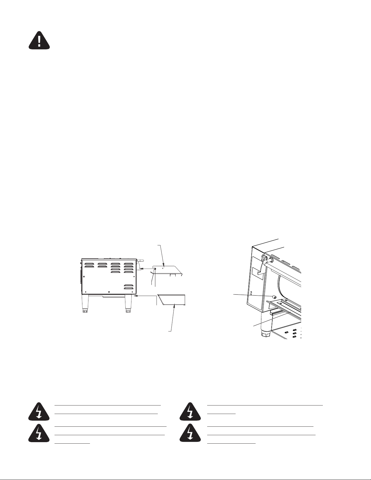
Before using the unit for the first time, make certain to clean it properly. Refer to the "Cleaning Procedure"
document for cleaning instructions. The inlet and outlet trays and scraper will also need to be placed on the
unit prior to use. The output tray slides on the lip under and in front of the drum area and the inlet tray sits
on a rod in the rear and the pins on its side sit on two brackets that protrude from the front. The scraper sits
on a bar on the bottom and must be installed so that the stop pin on the left side is above it to keep it from
rotating up and contacting the drum.
inlet tray
place here
place here
outlet tray
stop pin
scraper
ELECTRICAL CONNECTION
Before making any electrical connection to this unit, check that the power supply is adequate for the
voltage, amperage, and requirements stated on the rating plate. RTW14E units will require a NEMA
5-15R receptacle. RTW20E units will require a NEMA 6-15R receptacle. Make certain to disconnect the
unit from the power source before installing or removing any parts. Be absolutely sure that the ground
connection for the receptacle is properly wired. Do not connect equipment to power without proper
ground connections. Improper grounding may result in personal injury or fatality.
DO NOT CUT OR REMOVE THE PLUG OR DO NOT IMMERSE OR LET THE UNIT STAND
GROUNDING PRONG FROM THE PLUG. IN WATER.
CONNECT UNIT INTO DEDICATED AC LINE DO NOT HOSE DOWN THE UNIT OR THE
ONLY AS SPECIFIED ON THE DATA PLATE TABLE/COUNTER IF THE UNIT IS ON THE
OF THE UNIT. TABLE/COUNTER.
2
Page 7
DAILY OPERATION
CERTAIN SURFACES ARE EXTREMELY HOT DURING OPERATION AND
CARE SHOULD BE TAKEN WHILE USING THIS UNIT.
THIS UNIT IS DESIGNED TO WARM DRY, FLEXIBLE PRODUCTS ONLY.
DO NOT ATTEMPT TO RUN WET OR LOOSE MATERIAL THROUGH IT.
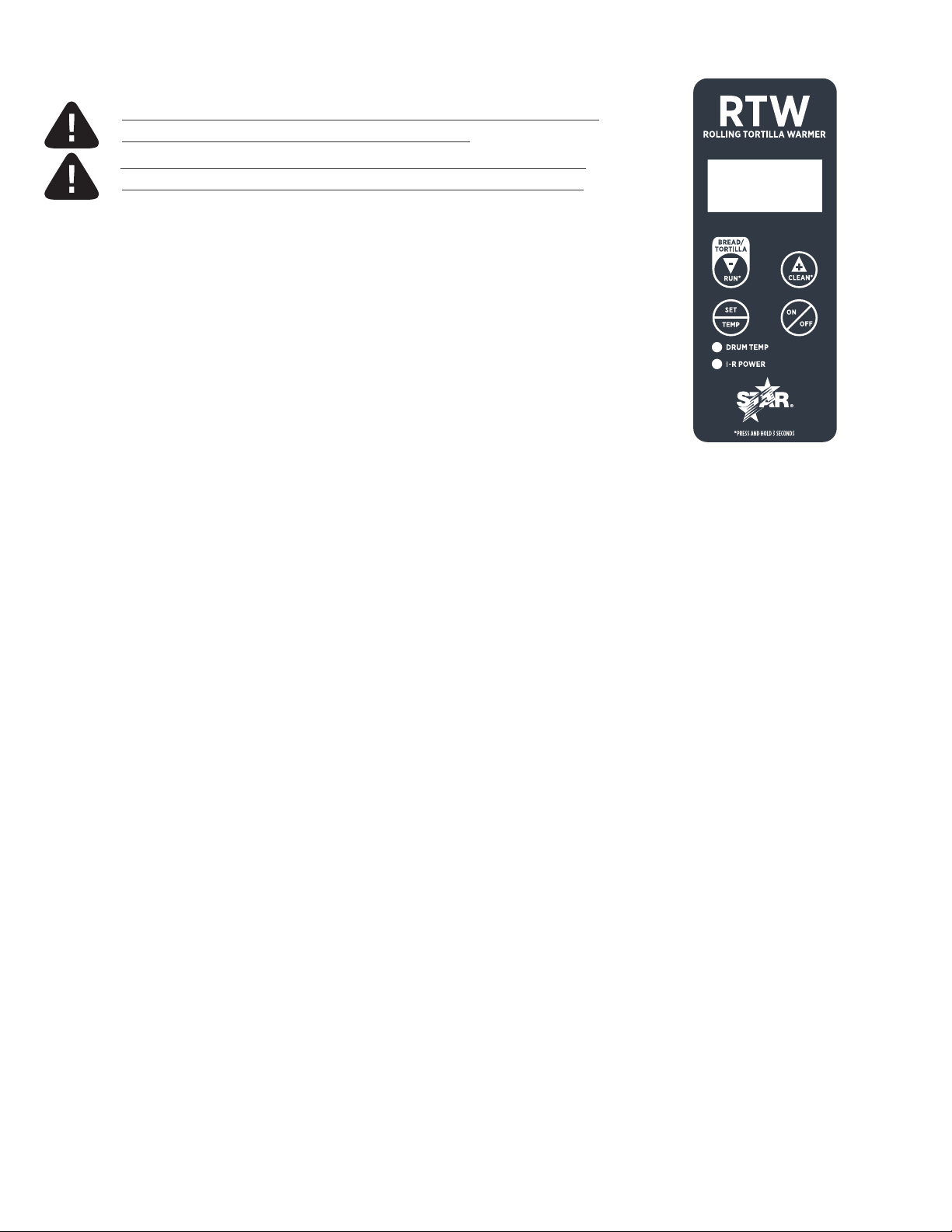
ELECTRONIC CONTROLS
BUTTONS (PRIMARY USES)
• ON/OFF—Turns power on or o to the electrical components of the unit.
• SET/TEMP—Allows adjustment of the roller heating element temperature
up to 450°F (232°C).
• ▲/CLEAN—Accesses “CLEAN” mode and adjusts settings upward in menus.
• ▼/RUN— Accesses “RUN” mode and adjusts settings downward in menus.
FUNCTIONS/MODES
• ON/OFF—All power is turned on, or removed from, the drum motor, heating
elements, and cooling fan. After powering down, the screen will
display “OFF” until the “ON/OFF” button is pressed again. Cooling
fan will be on in all modes other than when the unit is powered down.
• PREH E AT—Drum motor runs at the set “TORT” speed. Heaters bring the drum
temperature up to the set operating temperature.
• TORT—Drum motor runs at the set “TORT” speed. Heaters maintain the drum
temperature at the set operating temperature.
• BREAD—Drum motor runs at the set “BREAD” speed. Heaters maintain the
drum temperature at the set operating temperature. This mode only
lasts for 1–40 seconds before defaulting back to TORT mode.
• OPEN—Drum motor does not run. Heaters are o.
• COOL— Drum motor runs at the set “TORT” speed. Heaters are o.
• CLEAN— Drum motor does not run. Heaters are o.
1/2 scale RTW
control panel
START-UP
i. When the unit is initially plugged in, the display will read “OFF” for a brief time. No outputs will
receive power at this time.
ii. When “ON/OFF” is pressed, the drive motor, heating elements, and fan motor will be turned on.
The PREHEAT mode will start immediately and will take approximately twenty (20) minutes
to complete. During this time, “PREHT” will appear on the display. Do not attempt to adjust
temperature or speed settings until PREHEAT has completed.
iii. The temperature of the drum can be checked at any time in PREHEAT or TORT modes by pressing
the “SET/TEMP” button. If the temperature has not yet reached 100°F (38°C), the words “LOW”
and “TEMP” will flash on the screen.
iv. There will be a small dot on the lower right of the screen which will remain on whenever the heating
elements are on. When the PREHEAT mode has completed, “TORT” will be displayed on the screen.
3
2M-Z19213 Rev D - Owner's Manual for RTW Rolling Tortilla Warmer
Page 8

UNITS OF TEMPERATURE SELECTION
With the machine OFF hold the “SET/TEMP” and “▲/CLEAN” buttons. Once the menu pops up hit the
“SET/TEMP” button to scroll through until “SCALE” is displayed on the screen. At this point hit the
“▲/CLEAN” button to toggle between Fahrenheit and Celsius. Continue scrolling through using the
“SET/TEMP” button until the screen read “OFF” again. DO NOT MAKE ANY OTHER CHANGES WHILE
IN THIS MENU.
TEMPERATURE ADJUSTMENT
This can be performed in RUN (TORT or BREAD) and CLEAN modes.
i. Press and hold the “SET/TEMP” button for three (3) seconds. The display flashes the drum temperature
setting and the “DRUM TEMP” light on the front label illuminates as well.
ii. Use the ▲ and ▼ buttons to adjust the drum heat to the desired temperature. The display will stop
flashing while ▲ or ▼ are pressed and will indicate the temperature and units. The temperature can
be adjusted from 210°F–450°F (99°C–232°C). Adjustments of 10°F or 10°C at a time can be made
depending on which the unit is set to read at the time adjusted. The default setting is 430°F (221°C).
iii. Press the “SET/TEMP” button when you are satisfied with your adjustment and the screen will display
the top element power setting.
iv. Press the “SET/TEMP” button to exit this mode.
DRUM SPEED ADJUSTMENT
This can be performed in RUN mode (TORT or BREAD).
i. Press and hold the ▲ and ▼ buttons simultaneously for three (3) seconds. The display will sequence
through “TORT”, “SPEED”, and the current “TORT SPEED” speed setting number.
ii. Press the ▲ button to increase the set speed and the ▼ to decrease the set speed. The speed setting can
range from 1–99 and holding the ▲ or ▼ button will make the setting increase or decrease until a limit
is reached.
iii. Press “SET/TEMP” again to save the selected setting. The display will now sequence through “BREAD”,
“SPEED”, and the current “BREAD SPEED” setting number. This is adjusted using the same procedure
as the above “TORT SPEED” in the section above.
iv. Press the “SET/TEMP” again to save the selected setting. The display will now sequence through
“BREAD”, “TIME”, and the current time setting. Bread mode is only activated for a brief time determined
by this setting. Press the ▲ button to increase the set time and the ▼ to decrease the set time anywhere
from 1–40 seconds and holding the ▲ or ▼ button will make the setting increase or decrease until
a limit is reached.
v. Pressing “SET/TEMP” one more time will exit speed adjustment.
4
Page 9

CLEANING
DO NOT IMMERSE OR LET THE UNIT STAND
IN WATER.
DO NOT HOSE DOWN THE UNIT OR THE
TABLE/COUNTER IF THE UNIT IS ON THE
TABLE/COUNTER.
DO NOT USE CAUSTIC CLEANERS ON ANY
SURFACE OF THE UNIT.
Preventive maintenance for your unit consists of the following recommended cleaning procedures.
In order to keep your tortilla warmer in top operating condition, these steps should be performed
daily or weekly as indicated.
CLEAN MODE
CLEAN mode is a cool down notification feature alerting the user when the unit reaches a safe handling
temperature. Press the “▲/CLEAN” button for at least 3 seconds to activate CLEAN mode. The inlet and
outlet trays and scraper are removable for easy access for cleaning. The recommended cleaner to use is
Kay QSR heavy-duty degreaser.
CLEANING PROCEDURE
i. Press and hold the “▲/CLEAN” button to enter CLEAN mode. The screen will flash between “CLEAN”
and “WAIT” until the unit reaches a safe temperature at which time it will flash “CLEAN” and “READY ”.
ii. Remove the inner, top cover assembly and wipe it down with a damp cloth.
iii. Remove the inlet tray and wash using warm water and mild detergent.
iv. Wipe the drum using a damp cloth.
v. Reassemble the parts previously removed.
RTW14E
Wipe with damp cloth.
Clean using warm water
and detergent.
Clean using warm water
and detergent.
.
5
2M-Z19213 Rev D - Owner's Manual for RTW Rolling Tortilla Warmer
Page 10

MAINTENANCE
POWER MUST BE REMOVED FROM THE UNIT
BEFORE ATTEMPTING MAINTENANCE OR SERVICE.
CLEANING THE AIR INTAKE
DISCONNECT UNIT FROM POWER SOURCE
i. Use a vacuum or wipe down with a damp cloth to remove debris.
LUBRICATING THE CHAIN AND SPROCKETS (recommended every 6 months)
DISCONNECT UNIT FROM POWER SOURCE
i. Remove the screws holding the right side panel and remove the panel.
ii. Use an extreme pressure synthetic chain lubricant rated up to at least 400°F (204°C) [Star part number
1L-Z12397] and liberally lubricate the chain and sprockets.
iii. Reinstall the rear and side panels using the previously removed hardware.
§REPLACING THE FAN MOTOR
DISCONNECT UNIT FROM POWER SOURCE
i. Remove the screws holding the rear panel and lower the panel.
ii. Remove the four [4] screws holding the fan motor and fan guard in place.
iii. Unplug the power supply cord from the fan motor and remove the old motor.
iv. Place the replacement motor and existing fan guard in place and secure with previously removed hardware.
v. Reconnect the power supply cord to the fan motor.
vi. Secure the rear panel using the previously removed hardware.
REPLACING THE BELT DRIVE MOTOR
DISCONNECT UNIT FROM POWER SOURCE
i. Remove the screws holding the right side panel and remove the panel.
ii. Remove the drive motor sprocket and chain from drive motor.
iii. Remove the screws holding the rear panel and lower the panel.
iv. Disconnect the tachometer connection on the top of the drive motor.
v. Disconnect the drive motor wire connection from the control board.
vi. Remove the four [4] screws securing the drive motor and remove the drive motor out of the rear of the unit.
vii. Install the new drive motor using the previously removed hardware.
viii. Connect the new drive motor wire connection from the control board.
ix. Reconnect the tachometer to the top of the drive motor.
x. Connect the drive motor sprocket and chain, making sure to line it up with the driven sprocket. The two
sprockets should line up parallel with each other, so the chain does not twist any during operation.
xi. Reinstall the rear and side panels using the previously removed hardware.§
6
Page 11

WIRING DIAGRAM
POWER MUST BE REMOVED FROM THE UNIT BEFORE ATTEMPTING REPAIR OR SERVICE.
MAKE CERTAIN TO CHECK ALL CONNECTIONS THOROUGHLY BEFORE RESTORING POWER
TO THE UNIT. THE BELOW INFORMATION IS FROM WIRING DIAGRAM WD-Z20778.
Please review the following information before proceeding with any electrical diagnosis or repair.
i. Check for proper voltage jumper connection on power board.
ii. Fan cord, communication cable, IR sensor cable, and tachometer are not numbered.
iii. Hold back-up nut when tightening element terminals to prevent twisting the cold pin.
iv. Make certain that infrared sensor is supported when inserting connector.
IR ELEMENT:
POWER CONTROL
7-WIRE COMMUNICATION
4-WIRE IR SENSOR
LSS (LID SW)
3
LSS
1
CONTROL BOARD BACKSIDE
DRUM ELEMENT:
POWER CONTROL
CF
2
FC
L1 M1
OT2 L2 M2 F2 OT1 HB2 HT2
F1
HT1
HB1
120 V
240 V
240 V
120 V
4
POWER BOARD
I/O BOARD
T/C
YEL (+) RED(-)
WHT
POWER
SUPPLY
4-WIRES
5-WIRES
MOTOR
BLK
WHT
BLKGND
7
2M-Z19213 Rev D - Owner's Manual for RTW Rolling Tortilla Warmer
Page 12

CENTER DRUM, ROLLERS, AND ELEMENTS
RTW14E-120 pictured
4
81
2
41
67G
5
67B
67A
67B
67D
67E
28
25
67C
9
67F
31
30
38
39
12
43
30
48
3
3
74
78
14
38
75
68
66
SCRAPER ASSEMBLY
RTW14E-120 pictured
8
80
68
Page 13

RIGHT SIDE [CHAIN DRIVE]
RTW14E-120 pictured
50
33
29
49
32
59
76
44
21
45
77
26
10
65C
54
55
7
49
29
65B
52
16
65C
56
4
84
65A
65B
16
51
25
34
23
70
29
65A
59
13
29
10
83
10
56
11
9
2M-Z19213 Rev D - Owner's Manual for RTW Rolling Tortilla Warmer
Page 14

LEFT SIDE
RTW14E-120 pictured
19
10
4
10
17
15
4
1
79
8
64
22
78
10
10 6
18
10
10
Page 15

REAR [1]
RTW14E-120 pictured
62
63
4
37
69
72
10
10
11
2M-Z19213 Rev D - Owner's Manual for RTW Rolling Tortilla Warmer
Page 16

REAR [2]
RTW14E-120 pictured
82
4
53
73
46
85
6
57
61
10
60
58
40
5
24
24
12
71
10
Page 17

CENTER SECTION
RTW20E-208 pictured
81
31
14
41
67
66
38
69
3
80
1
13
2M-Z19213 Rev D - Owner's Manual for RTW Rolling Tortilla Warmer
Page 18

PARTS LIST
REF NO MODEL PART NUMBER QTY DESCRIPTION PAGE NO
RTW14E 2A-Z5942 4 leg, 4-inch 10
1
RTW20E 2A-307628 4 leg, 6-inch 13
2 ALL RTW 2A-Z10076 6 spacer, steel 8
RTW14E 2A-Z18673 2 scraper support rod, RTW14E
3
RTW20E 2A-Z18701 2 scraper support rod, RTW20E
RTW14E-120
4
RTW20E-208 25
5 ALL RTW 2A-Z20081 1 hinge wiring barrel 8, 12
6 ALL RTW 2C-20301-32 3 nut, #10-24 hex acorn 10
7 ALL RTW 2A-Z20193 2 stando, #10-32 x 0.625-inch 9
8 ALL RTW 2C-Z13630 2 halp clamp, 0.25-inch diameter 10
9 ALL RTW 2A-Z20247 1 drum insert, drive end 8
10
11 ALL RTW 2C-Z7165 9 nut, #8-24 keps 9
12 ALL RTW 2A-Z20248 1 drum insert, element end 8
13 ALL RTW 2K-Y2968 1 bushing, strain relief 9
14
15 ALL RTW 2K-Y8571 1 snap bushing, 2.125-inch OD 10
16 ALL RTW 2A-Z8017 4 bushing, idler 9
17 ALL RTW 2P-Z19925 2 bearing, idler 10
18 ALL RTW D6-Z20045 1 drum element support 10
19 ALL RTW D6-Z20538 1 panel, left side 10
20 ALL RTW 2C-1505 4 screw #10-32 x 0.375-inch NP
21
22 ALL RTW 2M-Z18246 1 label, electronic control 10
23 ALL RTW 2C-1827 4 lock washer, #10 star 9
24
25
26 ALL RTW 2C-6349 4 screw, #8 x 0.375-inch [phillips head] 9
27 ALL RTW 2C-Y6138 2 rivet, 0.125 x 0.25-inch NP
28 ALL RTW 2C-Z10075 2 screw, 1/4-20 x 0.375-inch 8
29 ALL RTW 2C-Z18418 23 burr washer, 0.1875-inch x 0.375-inch 9
30 ALL RTW 2C-Z20246 8 screw, 1/4-20 x 0.75-inch 8
31 ALL RTW 2C-Z20398 2 washer, #10 flanged 8, 13
32 ALL RTW 2C-Z20417 2 screw, #10-32 x 0.75-inch 9
RTW14E
RTW20E 32
RTW14E 2A-Z20527 1 top cover handle, RTW14E 8
RTW20E 2A-Z20397 1 top cover handle, RTW20E 13
RTW14E
RTW20E 6
RTW14E
RTW20E 14
RTW14E
RTW20E 11
2C-200004
2C-Z6929
2C-1810
2C-200006
2C-200067
23
screw, 6-32 x 0.375 [phillips head] 8, 9, 10, 11, 12RTW14E-230 27
30
8
2
18
screw, #6-32 x 0.25-inch [phillips head] 8, 9
nut, #10-24 keps 9, 10, 11, 12
washer, 0.1875-inch 9
screw, #6-32 x 1-inch [phillips head] 12
13
14
Page 19

REF NO MODEL PART NUMBER QTY DESCRIPTION PAGE NO
33
RTW14E
2C-Z2594
4
nut, #6-32 hex with lock 9
RTW20E 6
34 ALL RTW 2C-Z4063 4 screw, #10-24 x 0.5-inch 9
35 ALL RTW 2C-Z5192 4 rivet, 0.1875-inch NP
36 RTW20E 2A-Z19909 8 stando, 0.219 x 0.035 x 0.500 NP
37
RTW14E
2C-Z9632
4
screw, #10-32 x 0.5-inch 11
RTW20E 8
RTW14E 2D-Z20318 2 top roller, RTW14E 8
38
39
RTW20E 2D-Z19995 2 top roller, RTW20E 13
RTW14E 2D-Z20320 1 drum, RTW14E
8
RTW20E 2D-Z20250 1 drum, RTW20E
40 ALL RTW 2E-Z12427 1 switch, door 12
RTW14E 2H-Z20530 1 reflector spacer, RTW14E 8
41
RTW20E 2H-Z20233 1 reflector spacer, RTW20E 13
42 ALL RTW 2M-Z7207 1 sticker, ground symbol NP
RTW14E-120 2N-Z20831 1 drum element, RTW14E-120
43
8RTW14E-230 2N-Z21113 1 drum element, RTW14E-230
RTW20E-208 2N-Z18567 1 drum element, RTW20E-208
44 ALL RTW 2P-Z18417 1 flange bearing, 0.5-inch 9
45 ALL RTW 2P-Z18422 1 thrust washer 9
46 ALL RTW D6-Z20933 1 power supply bracket 12
47 ALL RTW 2P-Z18423 1 thrust washer NP
48 ALL RTW 2P-Z18568 1 bearing, terminal end 8
49 ALL RTW 2P-Z19824 2 sprocket, idler 9
50 ALL RTW 2P-Z19926 2 bearing, chain slide 9
51 RTW14E 2P-Z20245 2 bearing, drive end 9
51F RTW20E 2P-Z19923 1 bearing, drive stub front NP
51R RTW20E 2P-Z19923 1 bearing, drive stub rear NP
52 ALL RTW 2P-Z20539 1 chain, 25-inch 100 links 9
53 ALL RTW 2U-Z19838 1 gear motor, 24 V 12
54 ALL RTW 2P-Z19950 1 sprocket, double 9
55 ALL RTW 2P-Z18415 1 chain, 18.75-inch 50 links 9
56 ALL RTW 2P-Z20049 1 sprocket 9
57 ALL RTW D6-Z20718 1 IR sensor retainer 12
58 ALL RTW 2P-Z8478 2 hinge 12
59
RTW20E 3
2P-Z8779
RTW14E
2
sprocket 9
60 ALL RTW 2A-Z20443 1 sensor holder 12
61 ALL RTW 2E-Z20415 1 IR temp sensor 12
62 ALL RTW 2R-Z18593 1 fan guard 11
RTW14E-120 2U-Z18557 1 fan, 120V
63
2U-Z18558 1 fan, 230V
11RTW14E-230
RTW20E-208
15
2M-Z19213 Rev D - Owner's Manual for RTW Rolling Tortilla Warmer
Page 20

REF NO MODEL PART NUMBER QTY DESCRIPTION PAGE NO
64 ALL RTW 2J-Z20026 1 controller, IR temp 10
65 ALL RTW D6-RTW038 2 idler assembly 9
65A ALL RTW D6-Z20383 2 idler bracket 9
65B ALL RTW 2P-Z8392 2 sprocket, idler 9
65C
66
66A
66B
66C
67
67A
67B
67C ALL RTW 2A-Z20025 2 reflector endcap 8
67D
67E
67F
67H ALL RTW 2A-Z20065 1 guide, hinge wiring 8
68
69
70
71 ALL RTW D6-Z19997 1 plunger switch bracket 12
RTW14E
RTW20E 2
RTW14E D6-RTW041 1 inlet tray assembly, RTW14E 8
RTW20E D6-RTW035 1 inlet tray assembly, RTW20E 13
RTW14E D6-Z20496 1 inlet tray, RTW14E
RTW20E D6-Z20314 1 inlet tray, RTW20E
RTW14E D6-Z20497 1 shield, inlet tray RTW14E
RTW20E D6-Z20315 1 shield, inlet tray RTW20E
RTW14E D6-Z20498 1 brace, inlet tray RTW14E
RTW20E D6-Z20080 1 brace, inlet tray RTW20E
RTW14E-120 D6-RTW042 1 top reflector, RTW14E-120
RTW14E-230 D6-RTW047 1 top reflector, RTW14E-230
RTW20E-208 D6-RTW027 1 top reflector, RTW14E-208
THE BELOW PARTS [67A–67H] ARE LISTED FOR IDENTIFICATION AND DIAGNOSIS PURPOSES, BUT CAN ONLY BE REPLACED AS AN ASSEMBLY [67]
RTW14E D6-Z20529 1 cover, top reflector, RTW14E 8
RTW20E D6-Z20041 1 cover, top reflector, RTW20E NP
RTW14E-120
RTW14E-230 8
RTW14E 2H-Z20366 1 reflector insulator, RTW14E 8
RTW20E 2H-Z20365 1 reflector insulator, RTW20E NP
RTW14E-120 2N-Z20238-120 1 reflector element, RTW14E-120
RTW14E-230 2N-Z20238-240 1 reflector element, RTW14E-230
RTW20E-208 2N-Z19839-208 1 reflector element, RTW14E-240
RTW14E 2D-Z20528 1 top reflector, RTW14E 8
RTW20E 2D-Z20040 1 top reflector, RTW20E NP
RTW14E D6-RTW043 1 scraper assembly, RTW14E 8
RTW20E D6-RTW037 1 scraper assembly, RTW20E 9
RTW14E D6-Z18686 1 cover, rear control RTW14E
RTW20E D6-Z19061 1 cover, rear control RTW20E
RTW14E-120 D6-Z20672 1 nameplate, RTW14E-120 NP
RTW14E-230 D6-Z21120 1 nameplate, RTW14E-230
RTW20E-208 D6-Z18715 1 nameplate, RTW20E-208
2C-Z20417
2C-35487
4
12
screw, #10-32 x 0.75-inch 9
NP
NP
NP
8
8
13
screw, #8-32 x 0.3125-inch [phillips head] 8
8
NP
11, 13
16
Page 21

REF NO MODEL PART NUMBER QTY DESCRIPTION PAGE NO
72 ALL RTW 2E-Z17513 1 power board 11
73 ALL RTW 2E-Z20780 1 power supply, 24 V DC 12
74 ALL RTW D6-Z20046 1 bracket, inlet tray pin left 8
75 ALL RTW D6-Z20047 1 bracket, inlet tray pin right 8
76 ALL RTW D6-Z20048 2 bracket, chain slide 9
77
RTW14E
D6-Z20305
2
cover, access hole 9
RTW20E 1
78 ALL RTW D6-Z20311 1 slide support, right 10
79 ALL RTW D6-Z20312 1 slide support, left 10
RTW14E D6-Z20499 1 tortilla slide, RTW14E 8
80
81
RTW20E D6-Z20313 1 tortilla slide, RTW20E 13
RTW14E D6-Z20534 1 top cover, RTW14E 8
RTW20E D6-Z20308 1 top cover, RTW20E 13
RTW14E D6-Z20535 1 top cover, rear RTW14E 12
82
RTW20E D6-Z20309 1 top cover, rear RTW20E NP
83 ALL RTW D6-Z20536 1 mount, gear motor 9
84 ALL RTW D6-Z20537 1 cover panel, right side 9
85 ALL RTW 2C-Z20722 2 screw, #10-24 x 0.375-inch 12
86 ALL RTW 2C-Z14619 2 screw, #4-40 x 0.25-inch [phillips head] NP
RTW14E-120 2E-200375 1 cord set, RTW14E-120
87
NPRTW14E-230 2E-Y9251 1 cord set, RTW14E-230
RTW20E-208 2E-Z19137 1 cord set, RTW20E-208
88 ALL RTW 2E-Z20416 1 harness, IR sensor NP
89 ALL RTW 2E-Z20779 1 harness, main NP
90 RTW14E 2C-1493 1 screw, #8-32 x 0.375-inch NP
91 RTW14E 2C-1505 4 screw, #10-32 x 0.375-inch NP
92 RTW14E-230 2E-Y9253 1 hood, left side RTW14E-230 NP
93 RTW20E 2C-Z20027 1 nut, toggle switch RTW20E NP
94 RTW20E 2P-Z19908 8 spring, 0.3-inch x 0.026-inch x 1-inch RTW20E NP
95 RTW20E D6-RTW028 1 stub drive assembly, front RTW20E NP
96 RTW20E D6-RTW029 2 spring loaded bearing assembly, RTW20E NP
97 RTW20E D6-RTW048 1 stub drive assembly, rear RTW20E NP
98 RTW20E 2A-Z20134 2 roller drive stub, RTW20E NP
17
2M-Z19213 Rev D - Owner's Manual for RTW Rolling Tortilla Warmer
Page 22

WALL MOUNT INSTALLATION
LAG SCREWS MUST BE INSTALLED INTO STUDS FOR SUPPORT OF THE RTW UNIT. FAILURE TO INSTALL
IN STUDS COULD RESULT IN DAMAGE TO UNIT AND/OR HARM TO PERSONS OR PROPERTY. STAR IS NOT
RESPONSIBLE FOR DAMAGE RELATED TO INCORRECT INSTALLATION OR FAULTY CONSTRUCTION.
THESE INSTRUCTIONS REFERENCE INSTALLATION SHEET NUMBER
16" O.C.
wall
stud
Step One—Insert lag bolts into wall.
Locate and mark center of wall studs. Make certain marks are level.
Do not fully
tighten lag bolt
into wall.
keyway
Step Two—Hang wall mount bracket.
Slide the wall mount bracket over the lag bolts
and down into the keyway on each side.
18
Page 23

Step Three—Tighten mounting bolts.
Once the bracket is properly positioned, tighten
lag bolts down the rest of the way. Install truss
screws in lower holes and tighten fully.
truss screws
Step Four—Finish installation.
Place tortilla warmer into bracket as shown below.
Align mounting holes on the bottom of unit with
the holes in wall mount bracket. Screw in button
socket screw[s] and tighten to secure.
lag screws
button
socket screw
19
2M-Z19213 Rev D - Owner's Manual for RTW Rolling Tortilla Warmer
Page 24

SPECIFICATIONS
E
B
D
13.9 in.
353 mm
5.8 in.
147 mm
A
RTW14E is the model
used in the se drawings.
2.7 in.
(69 mm)
(25 4 mm)
(203 mm)
C
1 in.
(25 mm)
10 in.
8 in.
0.4 in.
(10 mm)
CLEARANCES
Please allow at least ten [10] inches
(254 mm) of space to open the top
for cleaning if the unit is to remain
stationary. There should be at least
one [1] inch (25 mm) of clearance on
each side and behind the unit as well.
F
1 in.
(25 mm)
MODEL HE I GHT
[A]
in.
(mm)
RTW14E 12
(302)
RTW20E 14
(356)
MODEL CORD DISTANCE FROM
RTW14E1 10.7 in.
RTW20E1 14.5 in.
1 patent pending
WIDTH
[B]
in.
(mm)
19.6
(49 8 )
25.2
(640)
CONTROL SIDE [D]
(272 mm)
(368 mm)
DEPTH
in .
(mm)
19.7
(500)
19.7
(500)
LEG HEIGHT
[C]
in .
(mm)
4
(102)
6
(152)
CORD DISTANCE FROM
CONTROL REAR
VOLTS AMPS WATTS POWER
120
230
208/
240
1.4 in
(36 mm)
1.4 in
(36 mm)
10.05
5.3
6.4/
7.4
1206
1206
1340/
1760
INLET TRAY
WIDTH [E]
PLUG
5-15P
CEE 7/ 7
6-15P 71 lb.
14.1 in.
(358 mm)
19.4 in.
(493 mm)
APPROX.
SHIP
WEIGHT
59 lb .
(26.8 kg)
(32.2 kg)
APPROX.
WEIGHT
INSTALLED
50 lb.
(22.7 kg)
62 lb.
(28.1 kg)
OUTPUT TRAY WIDTH
[F]
13.4 in.
(340 mm)
18.9 in.
(480 mm)
5-15P
CEE 7/ 7
6-15P
20
Page 25

21
2M-Z19213 Rev D - Owner's Manual for RTW Rolling Tortilla Warmer
Page 26

STAR MANUFACTURING INTERNATIONAL INC.
10 Sunnen Drive
Telephone 800 264 7827 • Fax 314 781 5445
www.star-mfg.com
•
Saint Louis, Missouri 63143
Printed in the U.S.A. • 2M-Z19213 • Rev D • 06.2016
Specifications are subjec t to change without notice.
 Loading...