

Page 1

Rolling Tortilla Warmer
Owner’s Manual
Models
RTW14EA and RTW19EA
patent no. 9,516,883
This manual includes material related to installation,
use , cleaning, and care. Exploded view[s], as well
as any available parts list[s] and wiring diagram[s]
pertaining to the unit[s] covered by this manual are also
included.
This manual must be read and understood by all
persons using or installing this appliance. Contact your
Star dealer if you have any questions concerning
installation, use, or maintenance of this equipment.
DO NOT DISCARD THIS MANUAL.
RTW19EA
2M-Z19213 - Rev. G - 08.2018
Page 2

LIMITED EQUIPMENT WARRANTY
Star Manufacturing [as well as its subsidiaries] warranties new products
to be free from defects in material and/or workmanship for a period
of one [1] year from the date of original installation, except as noted
below. Defects that occur as a result of normal use, within the time
period and limitations defined in this warranty, will at Star’s discretion
have the parts replaced or repaired by Star or a Star-authorized service
agency.
THIS WARRANTY IS SUBJECT TO ALL LISTED CONDITIONS.
Repairs performed under this warranty are to be performed by a Starauthorized service agency. Star will not be responsible for charges
incurred or service performed by non-authorized repair agencies.
In all cases, the nearest Star-authorized service agency must be used.
Star will be responsible for normal labor charges incurred in the repair
or replacement of a warrantied product within 50 miles (80.5 km) of
an authorized service agency. Time and expense charges for anything
beyond that distance will be the responsibility of the owner. All labor
will need to be performed during regular service hours. Any overtime
premium will be charged to the owner. For all shipments outside the
U.S.A. and Canada, please see the International Warranty for specific
details.
It is the responsibility of the owner to inspect and report any shipping
damage claims, hidden or otherwise, promptly following delivery.
No mileage or travel charges will be honored on any equipment that is
deemed portable. In general, equipment with a cord and plug weighing
less than 50 lb. (22.7 kg) is considered portable and should be taken or
shipped to the closest authorized service agen cy, transportation prepaid .
PORTABLE EQUIPMENT EXAMPLES
• 514LL fryer
• 15MC and 18MCP hot food
merchandisers
• QCS1, QCS2, and RCS2 toasters
• 16PD-A pretzel merchandisers
• condiment dispensers except
HPD- and SPD-series models
• all pop-up toasters
• all pastry display cabinets
• all heat lamps • all accessories
CONTACT
Should you require any assistance regarding the operation or
maintenance of any Star equipment; write, phone, fax or email
our service department. In all correspondence mention the
model number and the serial number of your unit, as well as
the voltage or type of gas you are using.
Business hours are 8:00 a.m. to 4:30 p.m. Central Standard Time
Telephone Star/Toasmaster 314.678.6306
Fax 314.781.2714
Email customerservice@star-mfg.com
www.star-mfg.com • www.toastmastercorp.com
• J4R popcorn machine
• 12NCPW and 15NCPW nacho
merchandisers
• nacho cheese warmers except
11WLA-series models
• specialty food warmers except
130R, 11RW, and 11WSA models
• all butter dispensers
• all nacho chip merchandisers
WARRANTY EXCLUSIONS
THE FOLLOWING WILL NOT BE COVERED UNDER WARRANTY.
• Any product which has not been used, cleaned, maintained,
or installed in accordance with the directions published in the
appropriate installation sheet and/or owner's manual as well
as national and local codes, including incorrect gas, electrical,
or water connection. Star is not liable for any unit which has
been mishandled, abused, misapplied, subjected to chlorides, harsh
chemicals, or caustic cleaners, damaged from exposure
to hard water, modified by unauthorized personnel, damaged
by flood, fire, or other acts of nature [or God], or which have
an altered or missing serial number.
• Installation, labor, and job checkouts, calibration of heat controls,
air and gas burner/bypass/pilot adjustments, gas or electrical
system checks, voltage and phase conversions, cleaning
of equipment, or seasoning of griddle surface.
• Replacement of fuses or resetting of circuit breakers, safety
controls, or reset buttons.
• Replacement of broken or damaged glass components, quartz
heating elements, and light bulbs.
• Labor charges for all removable parts in gas charbroilers and
hotplates, including but not limited to burners, grates, and
radiants.
• Any labor charges incurred by delays, waiting time, or operating
restrictions that hinder a service technician’s ability to perform
service.
• Parts that fail or are damaged due to normal wear or labor for
replacement of Items that can easily be replaced during a daily
cleaning routine. such as but not limited to silicone belts, PTFE
non-stick sheets, knobs, control labels, bulbs, fuses, quartz heating
elements, baskets, racks, and grease drawers.
• Components that should be replaced when damaged or worn,
but have been field-repaired instead [eg. field-welded fry pots]
• Any loss of business or profits.
ADDITIONAL WARRANTIES
Specialty/chain specific versions may also have additional
and/or extended warranties.
PRODUCTS PARTS LABOR
Star Ultra-Max® griddles,
charbroilers, and hotplates
Star-Max® fryers, griddles,
charbroilers, and hotplates
2 years 2 years
2 years 2 years
Jetstar® popcorn poppers 2 years 2 years
Staltek™ roller grill coatings 5 years
chrome griddle surfaces [against
peeling]
cast iron grates, burners,
and burner shields
5 years
180 days
original Star or Toastmaster parts
sold to repair Star or Toastmaster
90 days
equipment
Service First 1 year
The fore going warrant y is in lieu of any and a ll other warranti es expresse d or implied and c onstitutes the e ntire warranty. 2M-Z21647 • Rev C • 02.2018
i
Page 3

TABLE OF CONTENTS
Warranty i
General Information and Installation 1–2
Daily Operation 3–4
Cleaning 5
Maintenance 6
Wiring Diagram 7
Exploded Views 8–13
Parts List 14–17
Wall Mount Installation 18–19
Specifications 20
Factory Settings Adjustment 21
ii
Page 4

NOTES
iii
Page 5

2M-Z19213 Rev G - Owner's Manual for RTW Rolling Tortilla Warmer
SAFETY SYMBOLS
These symbols are intended to alert the user to the
presence of important operating and maintenance
instructions in the manual accompanying the appliance.
THOROUGHLY INSPECT YOUR UNIT ON ARRIVAL
This unit has been tested for proper operation before leaving our plant to ensure delivery of your unit
in perfect condition. However, there are instances in which the unit may be damaged in transit. In the
event you discover any type of damage to your product upon receipt, you must immediately contact
the transportation company who delivered the item to you and initiate your claim with that company.
If this procedure is not followed, it may a ect the warranty status of the unit. Please record the model
number, serial number, voltage, and purchase date in the area below at the time of receipt..
Model Number
Serial Number
Voltage
Purchase Date
NOTICE
Using any part other than genuine Star factory supplied parts relieves the manufacturer of all liability.
Due to periodic changes in designs, methods, procedures, policies, and regulations, the specifications
contained in this sheet are subject to change without notice. Star reserves the right to change product
specifications and design without notice. Such revisions do not entitle the buyer to corresponding
changes, improvements, additions or replacements for previously purchased equipment. While Star
International Holdings Inc. exercises good faith e orts to provide information that is accurate, we are
not responsible for errors or omissions in information provided or conclusions reached as a result
of using the specifications. By using the information provided, the user assumes all risks in connection
with such use.
PLEASE REFER TO THE WARRANTY PAGE FOR SPECIFIC WARRANTY INFORMATION.
MAINTENANCE AND REPAIRS
Contact your local authorized service agent for service or required maintenance. Please have the
information in the above fields ready when you call to ensure a faster service.
AUTHORIZED SERVICE AGENT LISTING
Reference the listing provided with the unit or for an updated listing go to the website or call customer
service to find an agent.
Business hours: 8:00 a.m. to 4:30 p.m. Central Standard Time
Telephone: 314-678-6303
Fax: 314-781-2714
Email: customerservice@star-mfg.com
Website: www.star-mfg.com
1
Page 6
GENERAL SAFETY INFORMATION
This equipment is designed and sold for commercial use only, and is intended for use by personnel
trained and experienced in its operation. This is not sold for consumer use in and around the home
nor for use directly by the general public in food service locations.
Before using yo
ur new equipment, read and understand all the instructions and labels associated
with the unit prior to putting it into operation. Make sure all people associated with its use understand
the units operation and safety before they use the unit.
GENERAL INSTALLATION INFORMATION
The unit is shipped fully assembled and ready to plug into a standard outlet specified for its voltage
and amp draw. If improper electrical supply can be determined through troubleshooting, contact
a qualified electrician prior to using the unit. Removal or replacement of the power cord or plug will
void the warranty. Should you require assistance, contact your local authorized service agent for any
service or required maintenance.
Level unit using the adjustable feet under the unit [there is approximately 0.5 (1/2) inch of adjustment].
Allow enough space around the unit for adequate ventilation. It is recommended that you leave a ten
(10) inch gap on the top for cleaning if the unit is to remain stationary. The sides and back of the unit
require no additional clearance.
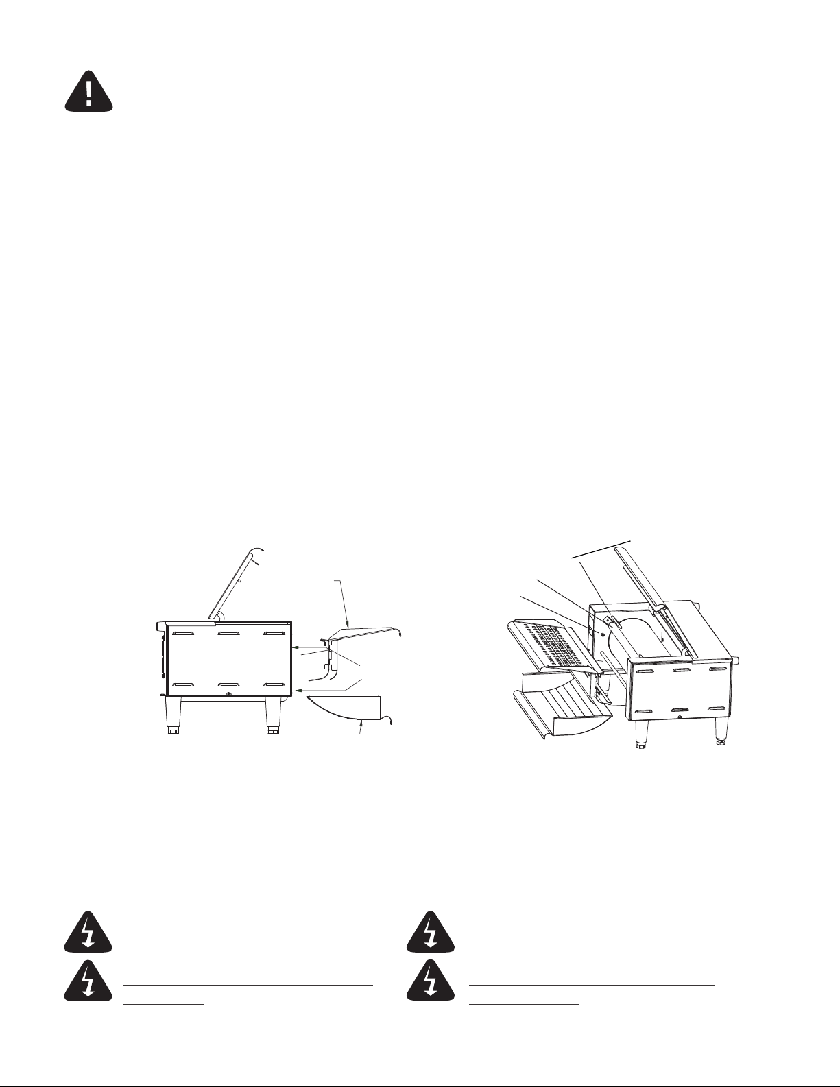
Before using the unit for the first time, make certain to clean it properly. Refer to the "Cleaning Procedure"
document for cleaning instructions. The inlet and outlet trays will also need to be placed on the unit prior to
use. The outlet tray slides on the lip under and in front of the drum area and the inlet tray sits on a rod,
resting against the stop pins.
belt guide
inlet tray
belt roller
stop pin
place here
outlet tray
ELECTRICAL CONNECTION
Before making any electrical connection to this unit, check that the power supply is adequate for the
voltage, amperage, and requirements stated on the rating plate. RTW14EA units will require a NEMA
5-20P receptacle. RTW19EA units will require a NEMA 6-15P receptacle. Make certain to disconnect the
unit from the power source before installing or removing any parts. Be absolutely sure that the ground
connection for the receptacle is properly wired. Do not connect equipment to power without proper
ground connections. Improper grounding may result in personal injury or fatality.
DO NOT CUT OR REMOVE THE PLUG OR DO NOT IMMERSE OR LET THE UNIT STAND
GROUNDING PRONG FROM THE PLUG. IN WATER .
CONNECT UNIT INTO DEDICATED AC LINE DO NOT HOSE DOWN THE UNIT OR THE
ONLY AS SPECIFIED ON THE DATA PLATE TABLE/COUNTER IF THE UNIT IS ON THE
OF THE UNIT. TABLE/COUNTER.
2
Page 7
2M-Z19213 Rev G - Owner's Manual for RTW Rolling Tortilla Warmer
DAILY OPERATION
CERTAIN SURFACES ARE EXTREMELY HOT DURING OPERATION AND
CARE SHOULD BE TAKEN WHILE USING THIS UNIT.
THIS UNIT IS DESIGNED TO WARM DRY, FLEXIBLE PRODUCTS ONLY.
DO NOT ATTEMPT TO RUN WET OR LOOSE MATERIAL THROUGH IT.
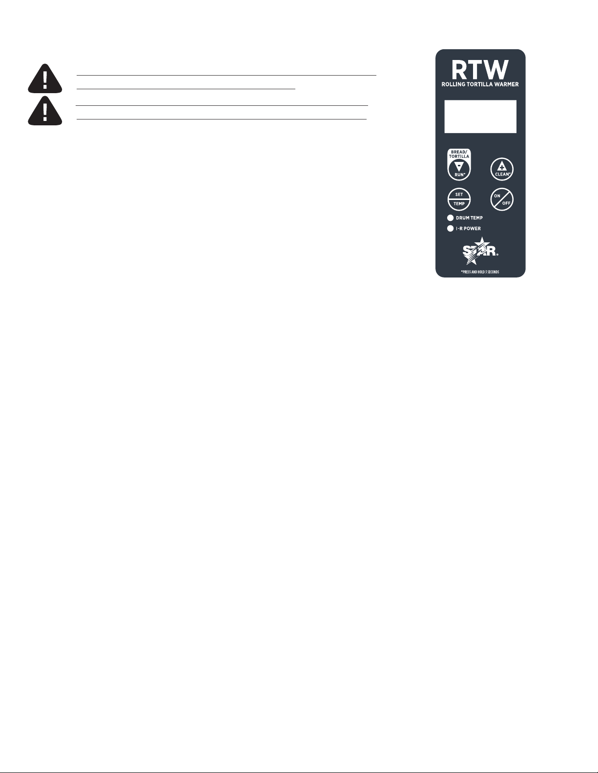
ELECTRONIC CONTROLS
BUTTONS (PRIMARY USES)
• ON/OFF—Turns power on or o to the electrical components of the unit.
• SET/TEMP—Allows adjustment of the roller heating element temperature
up to 480°F (249°C).
• ▲/CLEAN—Accesses “CLEAN” mode and adjusts settings upward in menus.
• ▼/RUN— Accesses “RUN” mode and adjusts settings downward in menus.
FUNCTIONS/MODES
• ON/OFF—All power is turned on, or removed from, the drum motor, heating
elements, and cooling fan. After powering down, the screen will
display “OFF” until the “ON/OFF” button is pressed again. Cooling
fan will be on in all modes other than when the unit is powered down.
• PREH EAT—Drum motor runs at the set “TORT” speed. Heaters bring the drum
temperature up to the set operating temperature.
• TORT—Drum motor runs at the set “TORT” speed. Heaters maintain the drum
temperature at the set operating temperature.
• BREAD—Drum motor runs at the set “BREAD” speed. Heaters maintain the
drum temperature at the set operating temperature. This mode only
lasts for 1–40 seconds before defaulting back to TORT mode.
• COOL— Drum motor runs at the set “TORT” speed. Heaters are off.
• CLEAN— Drum motor does not run. Heaters are off.
1/2 scale RTW
control panel
START-UP
i. When the unit is initially plugged in, the display will read “OFF” for a brief time. No outputs will
receive power at this time.
ii. When “ON/OFF” is pressed, the drive motor, heating elements, and fan motor will be turned on.
The PREHEAT mode will start immediately and will take approximately twenty (20) minutes
to complete. During this time, “PREHT” will appear on the display. Do not attempt to adjust
temperature or speed settings until PREHEAT has completed.
iii. The temperature of the drum can be checked at any time in PREHEAT or TORT modes by pressing
the “SET/TEMP” button. If the temperature has not yet reached 100°F (38°C), the words “LOW”
and “TEMP” will flash on the screen.
iv. There will be a small dot on the lower right of the screen which will remain on whenever the heating
elements are on. When the PREHE AT mode has completed, “TORT” will be displayed on the screen.
3
Page 8

TEMPERATURE ADJUSTMENT
This can be performed in RUN (TORT or BREAD) and CLEAN modes.
i. Press and hold the “SET/TEMP” button for three (3) seconds. The display flashes the drum temperature
setting and the “DRUM TEMP” light on the front label illuminates as well.
ii. Use the ▲ and ▼ buttons to adjust the drum heat to the desired temperature. The display will stop
flashing while ▲ or ▼
adjusted from 210°F–480°F (99°C–249°C). Adjustments of 10°F or 10°C at a time can be made
depending on which the unit is set to read at the time adjusted. The default setting is 480°F (249°C).
iii. Press the “SET/TEMP” button when you are satisfied with your adjustment and move on to a screen
which will allow you to toggle between Fahrenheit and Celsius.
iv. Press the “SET/TEMP” button again to save and exit this mode.
DRUM SPEED ADJUSTMENT
This can be performed in RUN mode (TORT or BREAD).
i. Press and hold the ▲ and ▼ buttons simultaneously for three (3) seconds. The display will sequence
through “TORT”, “SPEED”, and the current “TORT SPEED” speed setting number.
ii. Press the ▲ button to increase the set speed and the ▼ to decrease the set speed. The speed setting can
range from 1–99 and holding the ▲ or ▼ button will make the setting increase or decrease until a limit
is reached.
iii. Press “SET/TEMP” again to save the selected setting. The display will now sequence through “BREAD”,
“SPEED”, and the current “BREAD SPEED” setting number. This is adjusted using the same procedure
as the above “TORT SPEED” in the section above.
iv. Press the “SET/TEMP” again to save the selected setting. The display will now sequence through
“BREAD”, “TIME”, and the current time setting. Bread mode is only activated for a brief time determined
by this setting. Press the ▲ button to increase the set time and the ▼ to decrease the set time anywhere
from 1–40 seconds and holding the ▲ or ▼ button will make the setting increase or decrease until
a limit is reached.
v. Pressing “SET/TEMP” one more time will exit speed adjustment.
are pressed and will indicate the temperature and units. The temperature can be
4
Page 9

2M-Z19213 Rev G - Owner's Manual for RTW Rolling Tortilla Warmer
CLEANING
DO NOT IMMERSE OR LET THE UNIT STAND
IN WATER.
DO NOT HOSE DOWN THE UNIT OR THE
TABLE/COUNTER IF THE UNIT IS ON THE
TABLE/COUNTER.
DO NOT USE CAUSTIC CLEANERS ON ANY
SURFACE OF THE UNIT.
DO NOT USE ANY ABRASIVE CLEANING
UTENSILS ON ANY PART OF THE UNIT.
Preventive maintenance for your unit consists of the following recommended cleaning procedures.
In order to keep your tortilla warmer in top operating condition, these steps should be performed
daily or weekly as indicated.
CLEAN MODE
CLEAN mode is a cool down notification feature alerting the user when the unit reaches a safe handling
temperature. Press the “ON/OFF” button once to activate CLEAN mode. The inlet and outlet trays and
scraper are removable for easy access for cleaning. The recommended cleaner to use is Kay QSR
heavy-duty degreaser.
CLEANING PROCEDURE
i. Press and hold the “ON/OFF” button once to enter COOL DOWN mode. The screen will read “COOL”
until the unit reaches a safe temperature.
ii. Remove the silicone belt with the belt roller and wipe them down with a damp cloth.
iii. Remove the inlet and outlet tray. Wash using warm water and mild detergent.
iv. Wipe the drum using a damp cloth.
v. Reassemble the parts previously removed.
Wipe with damp cloth.
Belt Roller
Clean using warm water
and detergent.
Clean using warm water
and detergent.
RTW14EA
5
Page 10

MAINTENANCE
POWER MUST BE REMOVED FROM THE UNIT
BEFORE ATTEMPTING MAINTENANCE OR SERVICE.
CLEANING THE AIR INTAKE
DISCONNECT UNIT FROM POWER SOURCE
i. Use a vacuum or wipe down with a damp cloth to remove debris.
LUBRICATING THE CHAIN AND SPROCKETS (recommended every 6 months)
DISCONNECT UNIT FROM POWER SOURCE
i. Remove the screw holding the right side panel and remove the panel.
ii. Use an extreme pressure synthetic chain lubricant rated up to at least 400°F (204°C) [Star part number
1L-Z12397] and liberally lubricate the chain and sprockets.
iii. Reinstall the side panel using the previously removed hardware.
§REPLACING THE FAN MOTOR
DISCONNECT UNIT FROM POWER SOURCE
i. Remove the screws holding the rear panel and lower the panel.
ii. Remove the four [4] screws holding the fan motor and fan guard in place.
iii. Unplug the power supply cord from the fan motor and remove the old motor.
iv. Place the replacement motor and existing fan guard in place and secure with previously removed hardware.
v. Reconnect the power supply cord to the fan motor.
vi. Secure the rear panel using the previously removed hardware.
REPLACING THE BELT DRIVE MOTOR
DISCONNECT UNIT FROM POWER SOURCE
i. Remove the screws holding the right side panel and remove the panel.
ii. Remove the drive motor sprocket and chain from drive motor.
iii. Remove the screws holding the rear panel and lower the panel.
iv. Disconnect the tachometer connection on the top of the drive motor.
v. Disconnect the drive motor wire connection from the control board.
vi. Remove the four [4] screws securing the drive motor and remove the drive motor out of the rear of the unit.
vii. Install the new drive motor using the previously removed hardware.
viii. Connect the new drive motor wire connection from the control board.
ix. Reconnect the tachometer to the top of the drive motor.
x. Connect the drive motor sprocket and chain, making sure to line it up with the driven sprocket. The two
sprockets should line up parallel with each other, so the chain does not twist any during operation.
xi. Reinstall the rear and side panels using the previously removed hardware.§
6
Page 11

2M-Z19213 Rev G - Owner's Manual for RTW Rolling Tortilla Warmer
WIRING DIAGRAM
POWER MUST BE REMOVED FROM THE UNIT BEFORE ATTEMPTING REPAIR OR SERVICE.
MAKE CERTAIN TO CHECK ALL CONNECTIONS THOROUGHLY BEFORE RESTORING POWER
TO THE UNIT. THE BELOW INFORMATION IS FROM WIRING DIAGRAM 2M-Z22547.
Please review the following information before proceeding with any electrical diagnosis or repair.
DRUM ELEMENT:
TEMP CONTROL
CF
TSS
7
i. Check for proper voltage jumper connection on power board.
ii. Fan cord, communication cable, IR sensor cable, and tachometer are not numbered.
iii. Hold back-up nut when tightening element terminals to prevent twisting the cold pin.
iv. Make certain that infrared sensor is supported when inserting connector.
Page 12

CENTER DRUM, ROLLERS, AND ELEMENTS
RTW1 pictured
6
5
12
13
14
9
8
10
11
15
22
16
17
18
7
63
20
21
19
8
Page 13

RIGHT SIDE [CHAIN DRIVE]
RTW19EA pictured
30
29
31
32
29
33
28
27
26
28
24
23
25
18
41
52
9
2M-Z19213 Rev G - Owner's Manual for RTW Rolling Tortilla Warmer
Page 14

LEFT SIDE [PANEL]
RTW19EA pictured
36
34
35
37
39
38
17
40
10
Page 15

2M-Z19213 Rev G - Owner's Manual for RTW Rolling Tortilla Warmer
REAR [1]
RTW19EA pictured
35
43
49
44
22
45
36
42
48
60
61
29
46
47
51
50
64
53
54
55
56
22
59
34
18
41
58
50
51
57
11
Page 16

REAR [2]
RTW19EA pictured
51
50
50
12
51
53 39
64
54
Page 17

62
4
LOCTITE
3
1
2
LOCTITE
4
2M-Z19213 Rev G - Owner's Manual for RTW Rolling Tortilla Warmer
CENTER SECTION
RTW14EA pictured
13
Page 18

PARTS LIST
REF NO MODEL PART NUMBER DESCRIPTION QTY PAGE NO
RTW14EA 2D-Z20320 DRUM RTW14 1
RTW19EA 2D-Z22549 DRUM RTW19
2 ALL RTW 2A-Z20247 DRUM INSERT - DRIVE END 1 13
3 ALL RTW 2A-Z20248 DRUM INSERT - ELEMENT END 1 13
4 ALL RTW 2C-Z20246 1/4-20X3/4 LOW EHEAD SOC CAP SCREW 8 13
RTW14EA D6-RTW086 ASSY,TOP,FRONT, RTW-14 8
RTW19EA D6-RTW068 ASSY,TOP,FRONT, RTW-19 8
6 ALL RTW 2I-Z22463 BELT,SILCON,12"W 1 8
RTW14EA D6-RTW090 ASSY,ROLLER,IDLER,RTW-14 8
RTW19EA D6-RTW075 ASSY,ROLLER,IDLER,RTW-19 8
8 ALL RTW 2A-Z22577 BEARING,ROLLER,IDLER 2 8
9 ALL RTW 2C-70381 SCREW 1/4-20X3/4 SL TR MS 2 8
RTW14EA D6-RTW091 ASSY,ELEMENT,120V,1750W 8
10 1
11 ALL RTW 2P-Z21755 BEARING AND ELEMENT MOUNT 1 8
12 ALL RTW D6-Z22466 SUPPO RT,ELEMENT,DRUM 1 8
RTW14EA D6-RTW092 ASSY,ELEMENT,208-240V,1750W 8
RTW19EA D6-RTW074 ASSY,ELEMENT,208-240V,1750W 8
15
17
131
13 ALL RTW 2C-200121 WASHER #10 SPLIT SS 3 8
14 ALL RTW 2C-20301-32 NUT HEX ACORN 10-24 S/S 3 8
RTW14EA D6-Z22649 8
RTW19EA D6-Z22592 8
RTW14EA 2A-Z18673 INFEED SUPPORT ROD RTW14 8
16 1
RTW19EA 2A-Z22560 INFEED SUPPORT ROD RTW19 8
17 ALL RTW 2M-Z18246 LABEL, CONTROL TW ELEC 1 8
18 ALL RTW 2A-Z5942 FOOT, 1/2-13 X 4"L. 4 8
RTW14EA D6-Z22648-1 8
19 CATCH PAN WELDMENT 1
RTW19EA D6-Z22576-1 8
20 ALL RTW D6-Z22489-1 SU PPORT,BE ARING,PEM 2 8
RTW14EA D6-RTW089 ASSY,INFEED,RTW-14 8
21
RTW19EA D6-RTW067 ASSY,INFEED,RTW-19 8
RTW14EA D6-RTW083 ASSY,CHASSIS,RTW-14 8
22 1
RTW19EA D6-RTW065 ASSY,CHASSIS,RTW-19 8
23 ALL RTW D6-Z20933 POWER SUPPLY BRACKET 1 9
24 ALL RTW 2U-Z19838 GEARMOTOR 24V BLDC 15RPM 1 9
GUIDE,BELT 215
1
25 ALL RTW 2P-Z22457 SPROCKET,35BS11 .375ID 1 9
26 ALL RTW 2P-Z18415 CHAIN #35 18.75" 50 LINKS 1 9
14
Page 19

2M-Z19213 Rev G - Owner's Manual for RTW Rolling Tortilla Warmer
REF NO MODEL PART NUMBER DESCRIPTION QTY PAGE NO
27 ALL RTW 2P-Z22458 SPROCKET,35BS18 .500 ID 1 9
28 ALL RTW 2P-Z18423 THRUST WASHER HI-TEMP 4 9
29 ALL RTW 2C-Z6929 10-24 KEPS NUT S.S. 16 9
30 ALL RTW 2C-1810 WASHER 3/16 BURR STL NP
2
9
31 ALL RTW 2P-Z18417 FLANGE BEARING,1/2" 1 9
32 ALL RTW 2C-Z18418 BURR WASHER 3/16 X 3/8 SS 6 9
33 ALL RTW D6-Z22468-1 PLATE,DRUM,END 1 9
34 ALL RTW 2C-6349 SCREW #8X3/8 B THP STL NP 2 10
35 ALL RTW D6-Z22470 PANEL,SIDE 2 10
36 ALL RTW 2K-Y8571 BUSHING SNAP 2 1/8 1 10
37 ALL RTW 2C-31053 NUT 8-32 KEPS MS NICKEL 20 10
38 ALL RTW 2C-200467 CLAMP, NYLON WIRE 5/8 2 10
39 ALL RTW 2C-200067 SCREW 6-32X1/4 THP SS 9 10
40 ALL RTW 2J-Z20026 CONTROLLER, RTWE IR TEMP 1 10
RTW14EA 2E-200375 CORDSET, 14/3 5-15P TERMS
41
RTW14EA 2E-Z13852
ALL RTW
ALL RTW
2E-Z19137 CORDSET, 14/3 6-15P TERMS
2E-GR0411 CORDSET, 14/3 CH2-16P TERMS
CORDSET, 14/3 5-20P TERMS
1 11
42 ALL RTW 2K-Y6764 BUSHING - STRAIN RELIEF 1 11
RTW14EA D6-RTW087 ASSY,DEFLECTOR,AIR RTW14 11
43 1
RTW19EA D6-RTW072 ASSY,DEFLECTOR,AIR RTW19 11
44 ALL RTW 2T-Z22461 THERMOSTAT,HI-LIMIT 1 11
45 ALL RTW 2C-200200 NUT, 6-32 HEX 2 11
46 ALL RTW D6-Z20718 IR SENSOR RETAINER 1 11
47 ALL RTW 2A-Z20443 SENSOR HOLDER 1 11
48 ALL RTW 2E-Z20415 IR TEMP SENSOR 1 11
49 ALL RTW 2C-8833 SCREW 8-18X1/2 HEX STL NP 6 11
50 ALL RTW 2C-Z9632 10-32 X 1/2 SCREW FZA 6 11
51 ALL RTW 2R-200562 GUARD, FAN - WIRE 2 11
52 ALL RTW 2E-Z20780 POWER SUPPLY 24VDC 10W 1 11,12
RTW14EA 2U-200559 MOTOR,FAN 120V 23BTM
53 RTW14EA 1 11,12
2U-200561 MOTOR,FAN208-240V 23BTM
RTW19EA
54
RTW14EA
RTW19EA
D6-Z22634-1 COVER,TOP,REAR,PEM
D6-Z22567-1 1 11.12
COVER,TOP,REAR,PEM
1 11.12
55 ALL RTW 2I-Z0057 FOOT, RUBBER 2 11
56 ALL RTW 2C-3033 SCREW-MACH8-32X3/4 THP SS 2 11
57 ALL RTW 2C-Y6138 RIVET 1/8X.250 POP SS SM 14 11
15
Page 20

REF NO MODEL PART NUMBER DESCRIPTION QTY PAGE NO
58 ALL RTW 2M-Z18710 NAMEPLATE, BLANK RTW 1 11
59 ALL RTW 2P-Z8478 HINGE 2 11
60 ALL RTW 2M-Z7207 STICKER, GROUND SYMBOL 1 11
61 ALL RTW 2C-35736 NUT 8-32 HEX KEPS MS GREEN 1 11
62 1 13
RTW14EA D6-RTW093 ASSY,DRUM,RTW-14
RTW19EA D6-RTW071 ASSY,DRUM,RTW-19
RTW14EA D6-RTW085 ASSY,DRUM,SPROCKET,RTW-14
63 1 8
RTW19EA D6-RTW070 ASSY,DRUM,SPROCKET,RTW-19
64 ALL RTW 2E-Z17513 POWER BOARD 1 11
16
Page 21

WALL MOUNT INSTALLATION
LAG SCREWS MUST BE INSTALLED INTO STUDS FOR SUPPORT OF THE RTW UNIT. FAILURE TO INSTALL
IN STUDS COULD RESULT IN DAMAGE TO UNIT AND/OR HARM TO PERSONS OR PROPERTY. STAR IS NOT
RESPONSIBLE FOR DAMAGE RELATED TO INCORRECT INSTALLATION OR FAULTY CONSTRUCTION.
THESE INSTRUCTIONS REFERENCE INSTALLATION SHEET NUMBER 2M-Z21299.
16.000
O.C.
WOOD STUDS (BEHIND WALL)
STEP 1 - INSTALL LAG SCREWS (ITEM 1) INTO WALL
(SEE NOTE ON PAGE ***)
-!!!!DO NOT TIGHTEN LAG BOT FULLY INTO WALL!!!
-MARK AND LOCATE CENTER OF WALL STUDS
-STANDARD CONSTRUCTION IS 16" ON CENTER (O.C.)
REPRESENTATION WALL
A
REPRESENTATION
DETAIL A
SCALE 1 / 2
Do not fully
tighten lag bolt
into wall.
KEYWAY
DETAIL B
SCALE 1 / 2
4
STEP 2 - HANG RTW WALL MOUNT BRACKET(ITEM 4)
OVER LAG BOLTS-SLIDE DOWN INTO KEYWAY
17
2M-Z19213 Rev G - Owner's Manual for RTW Rolling Tortilla Warmer
Page 22

STEP 3 - FINISH TIGHTENING DOWN LAG BOLTS
AND INSTALL TRUSS SCREWS (ITEM 2)
AS SHOWN.
STEP 4 - PLACE TORTILLA WARMER INTO BRACKET
ALIGN MOUNTING HOLES ON BOTTOM OF UNIT
WITH HOLES IN WALL MOUNT BRACKET.
SCREW IN BUTTON SOCKET SCREW(S) (ITEM 3)
AND TIGHTEN TO SECURE.
1
2
BUTTON SOCKET SCREW
TIGHTEN WITH 5/16" ALLEN
WRENCH
ITEM
18
3
Wall Mount Parts List
P/N
2C-Z21298 HEX LAG SCREW, 2-5/16 X 2" X
1/2" HEX SIZE
2
2C-Z21297 K-LATH SCREW, TRUSS, #8, 1"
3
2C-Z19191 BOLT 1/2-13x1/2 BHSC SS
D6-Z226694
D6-Z22668
BRACKET,WALL MOUNT,RTW19EA
BRACKET,WALL MOUNT,RTW14EA
TITLE
SOCKET SCREW
INSTALLED
4X PLACES
QTY
21
2
4
1
Page 23

Rolling Tortilla Warmer
RTW14EA RTW19EA
E
D
MODEL HE I GHT
[A]
in .
(mm)
B
WIDTH
[B]
in .
(mm)
14.5 in.
370 mm
6.75
172 mm
A
DE P TH
in .
(mm)
CLEARANCES
Please allow at least ten [10] inches
RTW19EA is the model
used in these drawings.
in.
(254 mm) of space to open the top
for cleaning if the unit is to remain
stationary. There should be at least
one [1] inch (25 mm) of clearance on
each side and behind the unit as well.
8.1 in.
(206 mm)
C
5 in.
(76 mm)
LEG HEIG HT VOLTS AMPS WATTS POWER APPROX.
[C] PLUG SHIP
in . WEIGHT
(mm)
1 in.
(25 mm)
0.1 in.
(2.5 mm)
F
.5 in.
(12.7 mm)
5-15P
APPROX.
WEIGHT
INSTALLED
5-20P
RTW14EA
RTW19EA
MODEL CORD DISTANC E FR OM
RTW14EA 12.2 in. 2.1 in 14.1 in. 13 .0 in.
RTW19EA 14.0 in. 2.1 in 18.9 in. 18.0 in.
patent no. 9,516,883
Due to periodic changes in designs, methods, procedures, policies and regulations, the specifications contained in this sheet are subject to change
omissions in information provided or conclusions reached as a result of using the specifications. By using the information provided, the user assumes
all risks in connection with such use.
13
(305) (498) (541 ) ( 1 02)
13
(305) (610 ) (541 ) (102)
CONTROL SI
19.6 21.3
24.0 21.3
DE [D]
(310 mm) (53 mm) (358 m m) (330 mm)
(356 mm) (53 mm) (480 mm) (45 7 mm)
5
5
CORD DISTANCE FR OM
CONTR OL RE A R
120
208-240
208-240 1905-2537
STAR MANUFACTURING INTERNATIONAL INC.
Telephone 888 356 5362
•
Fax 314 781 5445
www.star-mfg.com
14.9
6.3-7.2
9.1-10.5
1,787 69 lb. 50 lb.
1,351-1787
5-15P
(31.4 kg) (22.7 kg)
P
6-15
P
6-15
IN LET TR AY OUTP UT TR AY WIDTH
77 lb. 62 lb.
(35.0 kg) (28.1 kg)
Printed in the U.S.A. • 2M-Z21286 • Rev E • 08.2018
Please refer to the owner’s manual for information
regard
ing installation or use.
[F]WI DTH [E]
r
19
CH2-16P
6-15P
Page 24

FACTORY SETTINGS ADJUSTMENT
i. With the machine OFF hold the “SET/TEMP” and “▲/CLEAN” buttons.
ii. While in this menu, the display alternately flashes a parameter and the current setting for that parameter.
iii. Use the ▲ and ▼ buttons to adjust the current parameter, then press the “SET/TEMP” button to move
to the next parameter. After moving through all parameters, "OFF" will once again appear on the screen.
DISPLAY D E FAULT DE S CRIPTI O N ADJUSTM E N T
READOUT SET TING
MOTOR BDC motor t ype [brushles s DC motor] -
DIR
PPM
RATIO
PREHT
OFFST
COOL
IRDRP
IRRCV
DIGIR
CCW drum rot ation d irec tion -
8250 m otor speed [pulse per minute] 0–1 5 ,000
10 turn down ratio of the drum speed 1–60
2 1–10
0
30 cool down timer setting [measu red in m inutes] 0–60
20 percent age of set po int tempe ratu re 1–99
180 tim er for IRDR P corre c tion 30 –300
YES digit al infra -red setting YES/ N O
time the heat system pau ses during prehe at cycle
[measure d in minutes]
oset adde d to raw d rum temp for disp lay
±2 00°F
(±93°C)
IRHPT
trigger s the IRRCV tim er when tem p erature is b elow this pe rce ntage of set point temper ature
if the I RDRP temper ature is bel ow the trigger point co ntinuously for th e en tire time, it will trigger
a "BAD PRO BE " fault condition
if the tempe ratu re is be low 300°F when tim e limit is reache d , a "BA D PR OBE " fau lt cond ition will be acti ve
STAR MANUFACTURING INTERNATIONAL INC.
Telephone 800 264 7827
18 pre heat mode tim er [measured in mi nute s] 1–30
Printed in the U.S.A. • 2M-Z19213 • Rev • 08.2018
Specifications are subject to change without notice.
•
Fax 314 781 5445
www.star-mfg.com
20
 Loading...