

Page 1
OPERATION MANUAL
Page 2

CONTENTS English
1 Introduction........................................................................................................2
1.1 Part specification..............................................................................................2
2 Installation.........................................................................................................3
2.1 Installing the instrument...................................................................................4
2.2 Electrical installation.........................................................................................4
3 Function overview............................................................................................5
3.1 How to use the push buttons ...........................................................................5
3.2 Position.............................................................................................................6
3.2.1 Time and date................................................................................................6
3.2.2 Battery voltage...............................................................................................6
3.3 Navigation functions.........................................................................................7
3.3.1 Cross track error (XTE).................................................................................7
3.3.2 Waypoint closure velocity (WCV).................................................................7
3.3.3 Time To Go (TTG).........................................................................................7
3.3.4 Select Waypoint.............................................................................................8
3.3.5 Man Over Board (MOB)................................................................................8
3.3.6 View the MOB position ..................................................................................8
3.3.7 Top arrows.....................................................................................................9
4 NMEA input .......................................................................................................9
5 Calibration.......................................................................................................10
5.1 Damping..........................................................................................................10
5.2 Unit for distance..............................................................................................11
5.3 Unit for speed .................................................................................................11
5.4 Seconds ON/OFF...........................................................................................11
5.5 Magnetic bearing ON/OFF.............................................................................11
5.6 Magnetic variation ..........................................................................................11
5.7 Circle alarm.....................................................................................................12
5.8 Cross track error alarm...................................................................................12
5.9 Road width ......................................................................................................12
6 Fault finding....................................................................................................13
7 Warranty ..........................................................................................................13
1
Page 3

1: INTRODUCTION English
1 Introduction
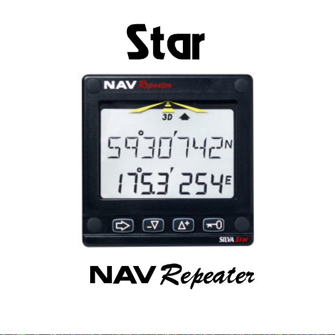
Thank you for choosing the Star NAV Repeater which will display all necessary
data from your NMEA navigator.
Power and NMEA data are connected on the reverse side of the instrument.
The colour coded 4-pole jack plug makes the installation easy.
1.1 Part specification
Star SEA Data is delivered with all mounting material. Make sure all these parts
are in the package.
QTY ITEM QTY ITEM
1 Instruction manual for use 1 Drill template
1 Warranty card 4 Mounting screws
1 Instrument SEA Data 4 Rubber plugs
11Instrument cover
Back cover
1 Screw connector
1 Bag with wire protectors and
silicon paste
2
Page 4

2: INSTALLATION English
2 Installation
• The installation includes 6 major steps:
1. Read the installation and operation manual.
2. Plan where to install the transducer and instrument.
3. Install the transducer, then the instrument.
4. Run the cables.
5. Take a break and admire your installation.
6. Learn the functions and calibrate your instrument.
• Before you begin drilling... think about how you can make the installation
as neat and simple as your boat will allow. Plan where to position the
instrument. Think about leaving space for additiona instruments in the
future.
• A few ”do not’s” you should consider:
- Do not cut cables too short. Allow extra cable length at the instrument so it
can be removed for inspection without having to disconnect attached
cables.
3
− Do not place sealant behind the instrument. The instrument gasket
eliminates the need for sealant.
− Do not run cables close to fluorescent light sources, engine or radio
transmitting equipment to avoid electrical disturbances.
− Do not rush, take your time. A neat installation is easy to do.
• The following material is needed:
Wire cutters and strippers.
Large Philips and small flat head screw driver.
Hole saw for the instrument clearance hole, 52 mm (2 1/16”).
2.8 mm (7/64 ”) drill for the mounting holes in wood.
3.2 mm (1/8 ”) drill for the mounting holes in fibre glass.
Plastic cable ties.
If you are doubtful about the installation, obtain the services of an
experienced technician.
Page 5
2: INSTALLATION English
2.1 Installing the instrument
• Place the adhesive drill template on the desired location for the instrument.
Drill the four screw holes using a 2.8 mm (7/64”) drill for wood or 3.2 mm (1/8”)
for fibre glass. Use a 52 mm (2 1/16”) hole saw to machine the clearance
hole for the instrument connection socket.
Note! Never drill through the instrument’s four mounting holes as the
gasket may be damaged and thus cause leakage. The warranty is not valid
for damage caused by drilling through the mounting holes.
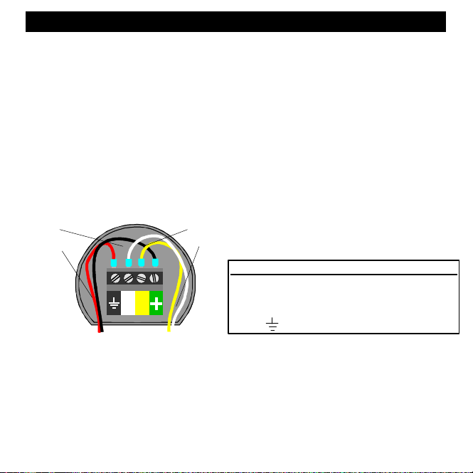
2.2 Electrical installation
The connector is attached to the four pins on the reversed side of the
instrument. The 4-pole jack plug is colour coded
BLACK
RED
WHITE
YELLOW
PLUG FUNCTION CABLE
Green: +12 V Own cable
Yellow: NMEA RETURN Own cable
White: NMEA IN Own cable
Ground : Ground (0 V) Own cable
Important! Always connect both NMEA in and NMEA return. Connect NMEA
return to ground if the GPS has no NMEA return.
Connect a 3 Ampere fast fuse between power
battery and instrument on the plus lead.
4
Page 6

3: FUNCTIONS English
3 Function overview
The display is divided in two function groups: Position and Navigation. To
change between them, press MODE. To scroll in function list, press UP or
DOWN.
3.1 How to use the push buttons
Mode / Light button
This button is used to change between Position mode and
Navigation mode. One short press changes between the two
modes. To select light levels, press mode for more than two
seconds.
Down button
This button is used to move down in the function list or to decrease
a value in set mode.
Up button
This button is used to move up in the function list or to increase a
value in set mode.
KEY button
This button is used to lock/unlock a value, to be able to change it.
Clear
To clear a value or reset trip distance, press UP and DOWN
together.
Man Over Board
To activate Man Over Board function, press MODE and KEY
together.
5
Page 7

3: FUNCTIONS English
3.2 Position
The position is displayed in latitude and longitude to three
decimal places. If the NMEA Navigator just sends two
decimals, the third will always read zero.
3.2.1 Time and date
To display date and time, press DOWN. Date and time is
displayed in month, day, hour, minute and second. Some
NMEA navigators does not send date. In that case, the
text TIME is written instead of the date. To set the local
time zone, press KEY. The ”underline” sign is flashing
(underline is the same as plus), change with UP or DOWN,
move to next character with MODE, change value with UP
or DOWN. When you have entered the correct time zone,
press KEY.
3.2.2 Battery voltage
To display battery voltage, press DOWN. Battery voltage is
measured in the instrument. It can therefore be different to
the voltage meter in your boat. That is due to voltage drop
in cables.
6
Page 8

3: FUNCTIONS English
3.3 Navigation functions
To change to combi steer, press MODE. The combi steer
window provides you with information of five values at a
time. The arrow at the top helps you to keep on track. This
function is explained in section 3.3.7. The functions
displayed are speed over ground, course over ground,
distance to Waypoint and course to Waypoint. If no
Waypoint is selected to navigate towards in the NMEA
navigator, the bottom row will display dashes.
3.3.1 Cross track error (XTE)
To display XTE, press DOWN. The XTE window displays
the XTE numerical on the top row. Bottom row displays
distance to and course to Waypoint. If no Waypoint is
selected to navigate towards in the NMEA navigator, the
bottom row will display dashes.
3.3.2 Waypoint closure velocity (WCV)
To display WCV, press DOWN. The WCV window displays
the WCV numerically on the top row. Bottom row displays
distance and course to Waypoint. If no Waypoint is
selected to navigate towards in the NMEA navigator, the
bottom row display dashes. If your boat is moving away
from the Waypoint, WCV will display dashes.
3.3.3 Time To Go (TTG)
To display TTG, press DOWN. The TTG window displays
the time to Waypoint. If no Waypoint is selected to navigate
to in the NMEA navigator or if your boat is moving away
from the Waypoint, TTG will display dashes.
7
Page 9

3: FUNCTIONS English
8
3.3.4 Select Waypoint
In the navigation mode you can at any time set a Waypoint
to go to. The NAV Repeater will then compute the distance
and bearing to Waypoint and all other functions.The
Waypoint is selected by pressing the KEY in any
navigation mode. When the KEY is pressed the NMEA
Waypoint number is displayed. To enter your Waypoint,
press UP or DOWN, the text Lat/Lon is displayed. Press
KEY and the present position is displyed, edit the
latitudecoordinate for your Waypoint. To increase/decrease
a value, press UP/DOWN, to move to next character, press
MODE. When ready with latitude, press KEY to lock. Edit the
longitude the same way as for the latitude and lock with KEY.
3.3.5 Man Over Board (MOB)
You can at any time press the MOB buttons, which will store
a Waypoint called MOB WP. The display will show course,
bearing and distance to MOB WP. To clear the MOB
function, press UP and DOWN together. The MOB WP is
stored in memory and can be selected again at any
time. It will be erased when a new MOB is pressed or at
power off.
3.3.6 View the MOB position
You can display the MOB position in latitude/longitude by
pressing KEY in navigation mode, press UP/DOWN until
MOB WP is displayed and press KEY again. The latitude
and longitude cannot be changed for safety reasons.
Page 10

mode
mode
3: FUNCTIONS English
3.3.7 Top arrows
At the top of the display there are four arrows and four text signs. The arrows
tell you if you are on the ”road” or not and the text displays the status of your
NMEA navigator .
You are off
the road, on
the left side
You are on
the left side
of the road
You are on the
right side of
the road
You are off
the road, on
the right side
The NMEA
navigator is in
2D or 3D
The NMEA
navigator is
in aqusition
The NMEA
navigator is in
differential
The width of the road can be adjusted, see calibration section 5.9. If you select
the road to be 0.050 Nm wide, the arrow will jump to the rightmost position
when the cross track error is greater than 0.050, Nm to the right. If the XTE is
less than 0.050 the arrow will jump to the second position from the right. If XTE
is zero, the two centre arrows will be displayed.
4 NMEA input
The NMEA is connected as explained in section 2.1. It is important to know that
the Star NAV Repeater only can repeat what is sent from the NMEA navigator it
is attatched to. Some NMEA navigators do not send all necessary data. It is
also important to know that some information is present only after selecting a
Waypoint in the NMEA navigator.
9
Page 11

5: CALIBRATION English
The following NMEA sentences are red for displaying different data. The
sentences are in priority order (i.e. if the NMEA navigater is sending more than
one sentence, the information in the first sentence is displayed.)
Position: 1. GGA, 2. RMC, 3. RMA, 4.GLL
Date and time: 1. ZDA, 2.RMC, 3.GGA, 4.GLL,
Speed Over Ground: 1. RMC, 2. RMA, 3. VTG
Course Over Ground: 1. RMC, 2. RMA, 3. VTG
Bearing To Waypoint: 1. BWC, 2. RMB, 3. BWR
Distance To Waypoint: 1. BWC, 2. RMB, 3. BWR
Time To Go: 1. Internally computed.
5 Calibration
To enter the calibration mode, press KEY for more than two
seconds. To scroll in the calibration list, press UP or DOWN.
To change a value or setting in the calibration, unlock with
KEY, change with UP/DOWN and lock the value with KEY
again.
5.1 Damping
The damping controls averaging time for computing speed
and course over ground. d0 is minimum damping and d9 is
maximum damping. Note! The minimum damping cannot be
faster than the NMEA navigators transmission.
5. BWC, 6.BWR
10
Page 12

5: CALIBRATION English
5.2 Unit for distance
The unit for distance can be selected as nautical miles (NM),
kilometres (KM) or miles (MI).
5.3 Unit for speed
The unit for speed can be selected as knots (KTS),
kilometres/hour (KMH) or miles/hour (MPH).
5.4 Seconds ON/OFF
Select the position to be displayed in seconds or hundreths of
minutes. If seconds is set to OFF, hundreths of minutes is
displayed.
5.5 Magnetic bearing ON/OFF
Select the bearing to display magnetic or true bearing. If
magnetic bearing is set to ON, all bearings will be computed to
magnetic using the magnetic variation set in 5.6.
5.6 Magnetic variation
Enter the local magnetic variation. The variation will be noted
in the sea chart. This function will have no effect if magnetic
bearings is set to OFF.
11
Page 13

5: CALIBRATION English
5.7 Circle alarm
The Star NAV Repeater has a built in arrival alarm. When
the boat is closer to the Waypoint than the setting in this
calibration mode, the alarm is activated. You can select the
radius of the circle. To turn off the alarm, set the value to
zero.
Note! Circle alarm limit is always in nautical miles.
5.8 Cross track error alarm
The Star NAV Repeater has a built in cross track error (XTE)
alarm. When the boats XTE is more than the setting in this
calibration mode, the alarm is activated. You can select the
XTE limit. To turn off the alarm, set the value to zero.
Note! XTE limit is always in nautical miles.
5.9 Road width
In this calibration mode you select the width of the road. This
is the setting for the arrows at the top.
Note! The road width is always in nautical miles
12
Page 14

6: FAULTFINDING English
6 Fault finding
The instrument has three fault messages. No INPUT, NO DATA and
UNKNOWN dATA.
Screen Cause Action
Blank
No input
No data
Unknown
data
GENERAL
All our products are designed and built to comply to the highest class industry standards. If the products
are correctly installed, maintained and operated, as described in the installation and operation manual,
they will provide long and reliable service. Our international network of distributors can provide you with the
information and assistance you may require virtually anywhere in the world.
Please read through and fill in this warranty card and send it to your national distributor for
product registration.
No power supply 1. Check fuse.
No signals are
registrated by the NAV
Repeater
Signals are recived but
non recognisable by
the NAV Repeater.
Wrong type of NMEA
are received
2. Check connections.
1. Check connections
2. Check if your NMEA
navigator is sending
data.
1.Check connections
2.Change polarity of
NMEA out A and B
3.Check baudrate
1.Check the manual
for NMEA output
settings.
WARRANTY
13
Page 15

WARRANTY English
LIMITED WARRANTY
The warranty covers repair of defective parts, due to faulty manufacture and includes labour when repaired
in the country of purchase. The warranty period is two years, and commences from the date of purchase.
The above warranty is the Manufacturers only warranty and no other terms, expressed or implied, will
apply. The Manufacturer specifically excludes the implied warranty of merchantability and fitness for a
particular purpose.
CONDITIONS
• The supplied warranty card and receipt with proof of purchase date, must be shown to validate any
warranty claim. Claims are to be made in accordance with the claims procedure outlined below.
• The warranty is non-transferrable and extends only to the original purchaser. The warranty does not
apply to Products from which serial numbers have been removed, faulty installation or incorrect fusing,
to conditions resulting from improper use, external causes, including service or modifications not
performed by the manufacturer or by its national distributors, or operation outside the environmental
parameters specified for the Product.
• The Manufacturer will not compensate for consequential damage caused directly or indirectly by the
malfunction of its equipment. The Manufacturer is not liable for any personal damage caused as a
consequence of using its equipment.
• The manufacturer, its national distributors or dealers are not liable for charges arising from sea trials,
installation surveys or visits to the boat to attend to the equipment, whether under warranty or not. The
right is reserved to charge for such services at an appropriate rate.
• The manufacturer reserves the right to replace any products returned for repair, within the warranty
period, with the nearest equivalent, if repair within a reasonable time period should not be possible.
• The terms and conditions of the warranty as described do not affect your statutory rights.
CLAIMS PROCEDURE
Equipment should be returned to the national distributor, or one of its appointed dealers, in the country
where it was originally purchased. Valid claims will then be serviced and returned to the sender free of
charge.
Alternatively, if the equipment is being used away from the country of purchase, it may be returned to the
national distributor, or one of its appointed dealers, in the country where it is being used. In this case valid
claims will cover parts only. Labour and return postage will be invoiced to the sender at an appropriate
rate.
DISCLAIMER
Common sense must be used at all times when navigating and the manufacturer’s navigation equipment
should only be considered as aids to navigation.
The manufacturers policy of continuous improvement may result in changes to product specification
without prior notice.
14
 Loading...