

Page 1
GAS
CHARBROILER
MODEL
OCB30, OCB30T, OCB30TH
OCB60, OCB60T, OCB60TH
& ACCESSORIES
Installation and
Operation
Instructions
2M-Z9210 Rev. B 8/26/11
OCB30TH
1
Page 2

2
These symbols are intended to alert the user to the presence of
important operating and maintenance instructions in the manual
accompanying the appliance.
RETAIN THIS MANUAL FOR FUTURE REFERENCE
NOTICE
Using any part other than genuine Star factory supplied parts relieves the
manufacturer of all liability.
Star reserves the right to change specications and product design without
notice. Such revisions do not entitle the buyer to corresponding changes,
improvements, additions or replacements for previously purchased
equipment.
Due to periodic changes in designs, methods, procedures, policies and
regulations, the specications contained in this sheet are subject to change
without notice. While Star International Holdings Inc., Company exercises
good faith efforts to provide information that is accurate, we are not
responsible for errors or omissions in information provided or conclusions
reached as a result of using the specications. By using the information
provided, the user assumes all risks in connection with such use.
MAINTENANCE AND REPAIRS
Contact your local authorized service agent for service or required maintenance.
Please record the model number, serial number, voltage and purchase date in the area below and have it ready when
you call to ensure a faster service.
SAFETY SYMBOL
Model No.
Serial No.
Voltage
Purchase Date
Business
8:00 am to 4:30 p.m. Central Standard Time
Hours:
Telephone: (314) 684-6303
Fax: (314) 781-2714
E-mail Parts@star-mfg.com
Service@star-mfg.com
Warranty@star-mfg.com
Website: www.star-mfg.com
Service Help Desk
Authorized Service Agent Listing
Reference the listing provided with the unit
or
for an updated listing go to:
Website: www.star-mfg.com
E-mail Service@star-mfg.com
Mailing Address: Star International Holdings Inc., Company
10 Sunnen Drive
St. Louis, MO 63143
U.S.A
2
Page 3

TABLE OF CONTENTS
SPECIFICATIONS . .. .. .. .. .. .. .. .. .. .. .. .. .. .. .. .. .. .. .. .. .. .. .. .. .. .. .. .. .. .. .. 1
GENERAL SAFTEY & WARNING INFORMATION . .. .. .. .. .. .. .. .. .. .. .. .. .. 2-3
GENERAL INSTALLATION DATA
Leg Caster Installation .. .. .. .. .. .. .. .. .. .. .. .. .. .. .. .. .. .. .. .. .. .. .. .. .. .. .. 4
Connecting Gas Supply . .. .. .. .. .. .. .. .. .. .. .. .. .. .. .. .. .. .. .. .. .. .. .. .. .. .. 5
Leveling the Unit .. .. .. .. .. .. .. .. .. .. .. .. .. .. .. .. .. .. .. .. .. .. .. .. .. .. .. .. .. .. 5
Checking for Gas Leaks - LP.. .. .. .. .. .. .. .. .. .. .. .. .. .. .. .. .. .. .. .. .. .. .. .. 5
Burner Adjustments . .. .. .. .. .. .. .. .. .. .. .. .. .. .. .. .. .. .. .. .. .. .. .. .. .. .. .. .. 5
DAILY OPERATION
Locating the grill . .. .. .. .. .. .. .. .. .. .. .. .. .. .. .. .. .. .. .. .. .. .. .. .. .. .. .. .. .. .. 6
Lighting Instructions . .. .. .. .. .. .. .. .. .. .. .. .. .. .. .. .. .. .. .. .. .. .. .. .. .. .. .. .. 6
Shutting Down Instructions .. .. .. .. .. .. .. .. .. .. .. .. .. .. .. .. .. .. .. .. .. .. .. .. .. 7
Cooking Grates & Radiants Cleaning & Inspecting . .. .. .. .. .. .. .. .. .. .. .. .. 7
Burner Removal & Cleaning .. .. .. .. .. .. .. .. .. .. .. .. .. .. .. .. .. .. .. .. .. .. .. .. 7
Cleaning . .. .. .. .. .. .. .. .. .. .. .. .. .. .. .. .. .. .. .. .. .. .. .. .. .. .. .. .. .. .. .. .. .. .. 8
Spiders Webs & Nest.. .. .. .. .. .. .. .. .. .. .. .. .. .. .. .. .. .. .. .. .. .. .. .. .. .. .. .. 8
Storage Daily & Long Term.. .. .. .. .. .. .. .. .. .. .. .. .. .. .. .. .. .. .. .. .. .. .. .. .. 8
ACCESSORIES
Hood & Wind Guard Installation .. .. .. .. .. .. .. .. .. .. .. .. .. .. .. .. .. .. .. .. .. .. 9
Removable Tank Caddy . .. .. .. .. .. .. .. .. .. .. .. .. .. .. .. .. .. .. .. .. .. .. .. .. .. .. 9
Installing LP Tank Cart Mounting Brackets .. .. .. .. .. .. .. .. .. .. .. .. .. .. .. .. .. 9
LP Tanks .. .. .. .. .. .. .. .. .. .. .. .. .. .. .. .. .. .. .. .. .. .. .. .. .. .. .. .. .. .. 10
Installing LP Tank to Caddy . .. .. .. .. .. .. .. .. .. .. .. .. .. .. .. .. .. .. .. .. 10
Mounting Caddy TO Charbroiler .. .. .. .. .. .. .. .. .. .. .. .. .. .. .. .. .. .. .11
Connecting Gas Supply Line . .. .. .. .. .. .. .. .. .. .. .. .. .. .. .. .. .. .. .. .11
Side Shelf Installation . .. .. .. .. .. .. .. .. .. .. .. .. .. .. .. .. .. .. .. .. .. .. .. .. .. .. .11
Steamer & Griddle Plate .. .. .. .. .. .. .. .. .. .. .. .. .. .. .. .. .. .. .. .. .. .. .. .. .. .11
Cleaning .. .. .. .. .. .. .. .. .. .. .. .. .. .. .. .. .. .. .. .. .. .. .. .. .. .. .. .. .. .. .11
Seasoning the Griddle Plate .. .. .. .. .. .. .. .. .. .. .. .. .. .. .. .. .. .. ..11-12
20# LP Tank Bracket Installation .. .. .. .. .. .. .. .. .. .. .. .. .. .. .. .. .. .. .. .. .. 12
Natural Gas Conversion .. .. .. .. .. .. .. .. .. .. .. .. .. .. .. .. .. .. .. .. .. .. .. .. .. 12
Checking for Leaks - NAT .. .. .. .. .. .. .. .. .. .. .. .. .. .. .. .. .. .. .. .. .. 12
WARRANTY . .. .. .. .. .. .. .. .. .. .. .. .. .. .. .. .. .. .. .. .. .. .. .. .. .. .. .. .. .. .. .. .. .. 13
OCB30 & OCB60 EXPLODED VIEW . .. .. .. .. .. .. .. .. .. .. .. .. .. .. .. .. .. .. .. .. 14
OCB30 & OCB60 PARTS LIST.. .. .. .. .. .. .. .. .. .. .. .. .. .. .. .. .. .. .. .. .. .. .. .. 15
OCB MANIFOLD EXPLODED VIEW .. .. .. .. .. .. .. .. .. .. .. .. .. .. .. .. .. .. .. .. .. 16
OCB MANIFOLD PARTS LIST .. .. .. .. .. .. .. .. .. .. .. .. .. .. .. .. .. .. .. .. .. .. .. .. 17
OCB ACCESSORIES.. .. .. .. .. .. .. .. .. .. .. .. .. .. .. .. .. .. .. .. .. .. .. .. .. .. .. .. .. 18
OCB ACCESSORIES PARTS LIST . .. .. .. .. .. .. .. .. .. .. .. .. .. .. .. .. .. .. .. .. .. 19
WARNING: Improper installation, adjustment,
alteration, service or maintenance can cause
property damage, injury or death. Read
the installation, operating and maintenance
instructions thoroughly before installing or
servicing this equipment.
FOR YOUR SAFETY: Do not store or use
gasoline or other ammable vapors or liquids
in the vicinity of this or any other appliance.
3
WARNING: This appliance shall be installed
in accordance with current regulations and
used only in well-ventilated space. Refer to
instructions before installing and using this
appliance.
In addition, there should be posted, in a
prominent location, detailed instructions to
be followed in the event the operator smells
gas. Obtain the instructions from the local
gas supplier.
Page 4

SPECIFICATIONS
Units are factory installed for LP gas and may be eld convertible to natural gas.
OCB30
Type: Radiant Style Manual Control
4 Controls for cooking burner; 70,000 BTUH Propane
1 Control for lighter tube
Cooking Surface 720 sq in (4645 sq. cm)
Approximate weight: Installed - 151 Lb (68.5 kg), Shipping - 200 Lb, (90.7 kg)
Dimensions: 32.5" - Width, 32.5" - Depth, 36" - Height
(82.5 cm - Width, 82.5 cm - Depth, 91.5 cm - Height)
OCB30T
Type: Radiant Style Manual Control
4 Controls for cooking burner; 70,000 BTUH Propane
1 Control for lighter tube
Tank Caddy 1-40lb. L.P. Cylinder and Tank Caddy
Cooking Surface 720 sq in (4645 sq. cm)
Approximate weight: Installed - 222 Lb (100.7 kg), Shipping - 279 Lb, (126.6 kg)
Dimensions: 32.5" - Width, 32.5" - Depth, 36" - Height
(82.5 cm - Width, 82.5 cm - Depth, 91.5 cm - Height)
OCB30TH
Type: Radiant Style Manual Control w/Hood
4 Controls for cooking burner; 70,000 BTUH Propane
1 Control for lighter tube
Tank Caddy 40lb. L.P. Cylinder and Tank Caddy
Cooking Surface 720 sq in (4645 sq. cm)
Approximate weight: Installed - 254 Lb (115.2 kg), Shipping - 321 Lb, (145.6 kg)
Dimensions: 32.5" - Width, 32.5" - Depth, 49" - Height
(82.5 cm - Width, 82.5 cm - Depth, 124.5 cm - Height)
OCB60
Type: Radiant Style Manual Control
8 Controls for cooking burner; 140,000 BTUH Propane
2 Control for lighter tube (1 for each cooking section)
Cooking Surface 1440 sq in (9290 sq. cm)
Approximate weight: Installed - 324 Lb (147 kg), Shipping - 398 Lb, (180.5 kg)
Dimensions: 65" - Width, 32.5" - Depth, 36" - Height
(165.1 cm - Width, 82.5 cm - Depth, 91.5 cm - Height)
OCB60T
Type: Radiant Style Manual Control
8 Controls for cooking burner; 140,000 BTUH Propane
2 Control for lighter tube (1 for each cooking section)
Tank Caddy 2-40lb. L.P. Cylinder and Tank Caddy
Cooking Surface 1440 sq in (9290 sq. cm)
Approximate weight: Installed - 437 Lb (198.2 kg), Shipping - 546 Lb, (247.7 kg)
Dimensions: 65" - Width, 32.5" - Depth, 36" - Height
(165.1 cm - Width, 82.5 cm - Depth, 91.5 cm - Height)
OCB60TH
Type: Radiant Style Manual Control w/Hood
8 Controls for cooking burner; 140,000 BTUH Propane
2 Control for lighter tube (1 for each cooking section)
Tank Caddy 2-40lb. L.P. Cylinder and Tank Caddy
Cooking Surface 1440 sq in (9290 sq. cm)
Approximate weight: Installed - 469 Lb (212.7 kg), Shipping - 588 Lb, (266.7 kg)
Dimensions: 65" - Width, 32.5" - Depth, 49" - Height
(165.1 cm - Width, 82.5 cm - Depth, 124.5 cm - Height)
1
Page 5
GENERAL SAFETY INFORMATION
CAUTION
This equipment is designed and sold for commercial use only by personnel trained and
experienced in its operation and is not sold for consumer use in and around the home nor
for use directly by the general public in food service locations.
Before using your new equipment, read and understand all the instructions & labels
associated with the unit prior to putting it into operation. Make sure all people associated
with its use understand the units operation & safety before they use the unit.
All shipping containers should be checked for freight damage both visible and concealed.
This unit has been tested and carefully packaged to insure delivery of your unit in perfect
condition. If equipment is received in damaged condition, either apparent or concealed, a
claim must be made with the delivering carrier.
Concealed damage or loss - if damage or loss is not apparent until after equipment is
unpacked, a request for inspection of concealed damage must be made with carrier within
15 days. Be certain to retain all contents plus external and internal packaging materials for
inspection. The carrier will make an inspection and will supply necessary claim forms.
The Star-Max™ series gas charbroiler is equipped for the type of gas indicated on the nameplate
mounted on the front panel. All units are shipped from the factory for use with LP. The unit can
easily be converted for use with Natural Gas, consult your dealer for more information.
-IMPORTANT-
OPERATE IN NON-COMBUSTIBLE OUTDOOR LOCATIONS ONLY!
The installation of the Appliance must conform to the NATIONAL FUEL GAS CODE
"ANSI Z223.1 - LATEST EDITION" AND ALL LOCAL GAS COMPANY RULES AND
REGULATIONS.
IN CANADA INSTALLATION SHALL BE IN ACCORDANCE WITH THE CURRENT
CAN/CGA-B149.1 NATURAL GAS INSTALLATION CODE OR CAN/CGA-B149.2
PROPANE INSTALLATION CODE AND LOCAL CODES WHERE APPLICABLE.
WARNING: Improper installation, adjustment, alteration, service or maintenance
can cause property damage, injury or death. Read the installation, operating
and maintenance instructions thoroughly before installing or servicing the
equipment.
FOR YOUR SAFETY
Do not store or use gasoline or other ammable vapors and liquids in the vicinity of this or any
other appliance. Keep the appliance area clear and free from combustibles.
WARNING
This appliance shall be installed in accordance with current regulations and used only in
well-ventilated space. Refer to instructions before installing and using this appliance.
In addition, there should be posted, in a prominent location, detailed instructions to be followed
in the event the operator smells gas. Obtain the instructions from the local gas supplier.
2
Page 6

GENERAL SAFETY INFORMATION (continued)
CAUTION - IMPORTANT SAFETY INFORMATION
• Always be sure gas is turned “off” at the burners and at the LP supply gas source when
unit is not in use.
• This unit shall be operated outdoors in a non-combustible location. Maintain 3 ft.
spacing around the unit for operation and servicing. DO NOT use on a recreational
vehicle or boat.
• Unit may be operated outdoors with “0” clearance to non-combustible materials in a noncombustible location. Do not operate under low hanging tree limbs or combustible roofs.
• Always provide adequate space around the unit for combustion air and ventilation air to
the unit. Do not operate the unit in a garage or other conned space.
• Unit can be very hot during operation and shall not be located in high trafc areas or
walk ways.
• Always lock the caster brakes on the wheels to prevent movement. Do not try to move
the unit during operation.
• Always inspect the exible gas hose(s) prior to use. Do not operate unit if there are
signs of abrasion or hose cracking.
WARNING: If damaged, replace hose/regulator prior to operating grill.
• Always use an approved horizontal LP tank secured in the supplied tank caddy. Be sure
the supply hose/regulator are securely attached to the tank valve. The fuel cylinder with
the tank caddy must be constructed and marked in accordance with the specications
for LP (propane) cylinder of the U.S. Department of Transportation or CAN/CSA B339.
The tank shall be a 40 lb. horizontal type, 12” in diameter and 29” in length with a safety
shut off valve and a type 1 QCC1 service outlet connection. It must be so designed to
provide ow-controlled vapor only in the horizontal position when mounted in the caddy.
Do not use a vertical tank in this caddy. Always turn tank supply valve on slowly when
operating grill.
• Unit may be stored indoors provided the LP (propane) cylinders are disconnected and
removed from the unit. Do not store cylinders in an area of high heat such as a
conned space in direct sunlight. Excessive pressure could develop inside of tanks.
Tanks shall be stored outdoors in a well-ventilated space and away from children. Tanks
shall always be secured in place during storage and when transported. Reference
NFPA58 storage and handling of LP gases or CAN/CGA B149.2. Propane gas
installation code.
• Propane gas is highly ammable and heavier than air. Always operate unit in a
well-ventilated space. Do not operate unit on LP at temperatures below 50°F (10°C) and
do not operate grill or locate unit in high wind locations.
• Periodically inspect burners and gas orices for blockage often caused by spiders build
ing webs in conned spaces. Do not operate grill if burner ashes back or is not
operating with an even burner ame. Allow unit to cool, inspect and clean suspect
burner and gas orice.
• Always inspect the front located pans and remove any grease and ash build up from
cooking operation. Do not restrict the ow of air into the bottom or front of the grill.
• This unit is shipped set up for LP propane gas operation. The unit can be converted
to Natural gas operation by changing out the burner and lighter tube orices. A natural
gas regulator should also be supplied (set for 5” water column pressure) or a regulated
gas supply provided to the unit manifold inlet. Do not expose the regulator to pressures
greater than 1/2 PSIG.
-
3
Page 7
GENERAL INSTALLATION DATA
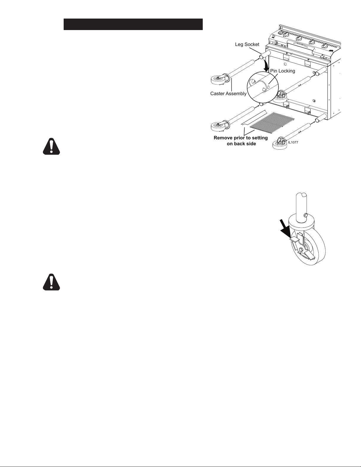
IL1077
Leg Socket
Caster Assembly
Pin Locking
Remove prior to setting
on back side
IL1080
LEG CASTER INSTALLATION
Remove all packing material from the unit.
Remove the cooking grates & radiants from the
unit and with the help of a second person set unit
on its back as shown in Fig. 1. Remove leg/caster
assembly from carton and attach in place on grill
leg sockets. Caster assemblies will slide into
the leg sockets and locks into position by the pin
lock snapping in place inside the socket hole.
After all 4 legs locks securely in position and with
the help of a second person, stand unit upright
and re-install the radiants & cooking grates.
CAUTION
THE GRILL MUST BE PLACED ON A
LEVEL SURFACE AND THE CASTERS
MUST BE LOCKED WHILE OPERATING
Fig. 1 (Above) Attaching leg casters to charbroiler
Fig. 2, (Left) Lock Wheel Casters when using grill
& before mounting tank caddy
THE GRILL TO PREVENT MOVEMENT.
ACCESSORIES INSTALLATION
Information regarding the installation of LP
Tanks and other accessories that are available
with this unit, See General Accessories
Installation Section starting on page 12.
CAUTION
Always use the tanks supplied with the tank caddy or a certied 40 lb. horizontal tank DOT
marked LP propane cylinders with mounting brackets. Never over ll tanks and always
use supported and secured in the horizontal position in the tank caddy. Once lled, the LP
(propane) tank caddy can be easily wheeled using the front handle provided on the cart.
Position the tank caddy in place under the grill (with previously installed hanger brackets)
with the tank valve end located to the front of the grill. Be sure grill caster wheels are locked
in place using wheel brakes provided so grill does not move. (See Figure 2).
4
Page 8
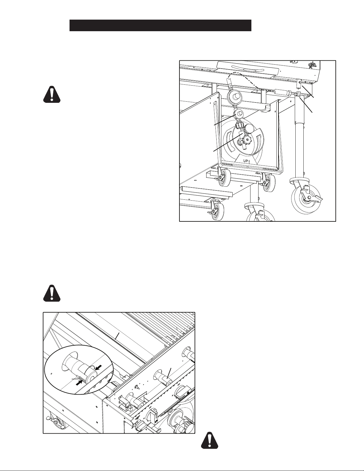
IL1091
Regulator Assy
Tank Outlet
Connector
Grill Inlet
90° Elbow
OCB30 only
Burner
Air Shutter
IL1092
Adj. Screw
air flow
air flow
GENERAL INSTALLATION DATA (continued)
CONNECTING GAS SUPPLY LINE
The grill regulator/hose assembly can then be attached to the 40 lb. tank outlet connector.
Remove the dust guard from the tank outlet connector and carefully screw the type 1
connector in place being careful not
to kink or damage the gas supply
line hose. Screw the connector to
the tank outlet connector hand tight,
DO NOT OVERTIGHTEN (Fig. 1).
Attach the other end to the Grill Inlet
using a wrench
On the 60 model, the left side hose
will mount to the left tank and the right
side hose to the right tank.
LEVELING THE UNIT
Before operating the unit, make sure
it is located on level ground. Units
performance can vary if it is on unlevel
surface
CHECKING FOR GAS LEAKS
Be sure all LP (propane) tanks are
OFF and all burners are in the “OFF”
position, pointing upward in the 12
o'clock position. Using a bubbly
water soap solution (or leak detection
solution), carefully brush all gas connections and slowly open the LP tank valve. Observe all
connections for bubbling to determine a gas leak. If a leak is found, immediately close the tank
valve and re-tighten the leaking gas connection, or call your local gas supplier or an authorized
dealer for service. DO NOT OPERATE GRILL WITH ANY GAS LEAK. If the gas connections
are leak free, the unit is now ready for operation.
Fig. 1, Connecting the Regulator Assembly from the LP Tank to the
Unit.
CAUTION
Matches, candle ame or other sources of ignition shall not be used for this
purpose.
Fig. 2, Adjusting the Burner Air Shutter to obtail proper ame.
5
BURNER ADJUSTMENT
This units Air Shutters were factory set and
should not need adjusting. If an adjustment is
needed follow these steps:
1. Light unit with cooking grills & radiants
removed, and set on High.
Note: it should look similar to Fig. 2.
2. If necessary, turn unit off, remove bullnose
to expose the Air Shutters, slowly decrease
openings of air shutters on burners to give
a soft blue ame having luminous tips, then
slowly increase openings to a point where
the yellow tips disappear and a hard blue
ame is obtained. Turn unit off and allow to
cool, when making these adjustments.
CAUTION
CHARBROILERS ARE HOT!
Page 9
DAILY OPERATION
2
1
IL1085
IL1114
LOCATING THE GRILL
When selecting a suitable location for your grill, take into account concerns such as wind exposure
and areas of high trafc. Do not locate the grill close to a home or any kind of combustible
construction. Do not locate overhead shading umbrellas or other combustible items near or
above the grill. Grill exhaust can be very hot and under extreme conditions can emit ames.
Maintain an open area around the grill and enclosure at all times, keeping the area free from
combustible materials, gasoline, and other ammable vapors and liquids. Be sure your grill is
located on a level surface.
LIGHTING INSTRUCTIONS
NOTE: It’s necessary to open the tank valves slowly to avoid an excess ow surge in the tank
connector safety tting which would cause the gas ow to the manifold to be reduced. This is
a safety feature designed to limit the ow of gas under an excessive ow condition and would
cause the burners to operate with a reduced ame. If this occurs, verify tanks are not empty
or running out of gas. Shut down the grill and “slowly” open the tank gas control valve. Follow
the lighting instructions outlines in steps 1 to 5.
NOTE: The rst time lighting of the appliance may take
longer because of the need to purge the air out of
the gas line and manifold.
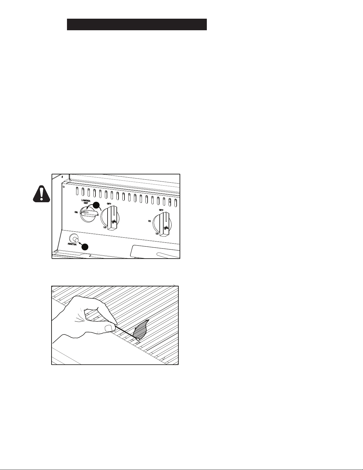
Fig. 1, Turn on Gas Supply and press the
igniter button to ignite the igniter tube.
Fig. 2, Use the lighter rod with a lit match to
ignite the igniter tube if the igniter button fails.
1. Be sure LP tank valves are turned “OFF” and are
secured in place. Be sure all knobs are turned
clockwise to “OFF”. If the unit has a hood, be sure
to open it.
2. Slowly open the LP tank gas valve counter clockwise
to allow gas ow to the side of the grill to be lit.
3. Turn the red knob counter clockwise to the “ON”
position and press in the igniter button on the side
to be lit. It may take several tries on the igniter
button to get the small igniter tube lit (Fig 1).
4. If the igniter button does not light the burner after
several tries, turn red knob to OFF position and
use the lighter rod supplied with the unit to hold a
match to light the igniter tube. Push and turn the
red knob counter clockwise to the “ON” position
and using a lit match attached to the lighter rod,
insert this down through the grates to light the 3/8”D
igniter tube. (Fig 2)
5. Verify that the entire length of the lighter tube is lit
and operating. If the lighter tube does not light,
turn off the gas supply, wait 5 minutes and attempt
to re-light the unit. Once the lighter tube is lit, the
burner knobs (black) can be pushed and turned
counter clockwise to the: “HI” position and the
burners should light.
6
Page 10
Burner
Radiants
Cooking Grates
IL1082
Burner
IL1084
Burner Slots
Compressed Air
3
Burner Inlet
IL1083
2
Ignitor Tube
Burner
Orifice
1
Rear Slot
DAILY OPERATION (continued)
SHUTTING DOWN INSTRUCTIONS
To shut down the unit, turn all knobs clockwise to the “OFF” position. Turn LP (propane) gas
cylinder control knob clockwise to the “OFF” position. If the unit is not to be used for a while,
disconnect LP (propane) gas supply lines from tank (s) for added safety.
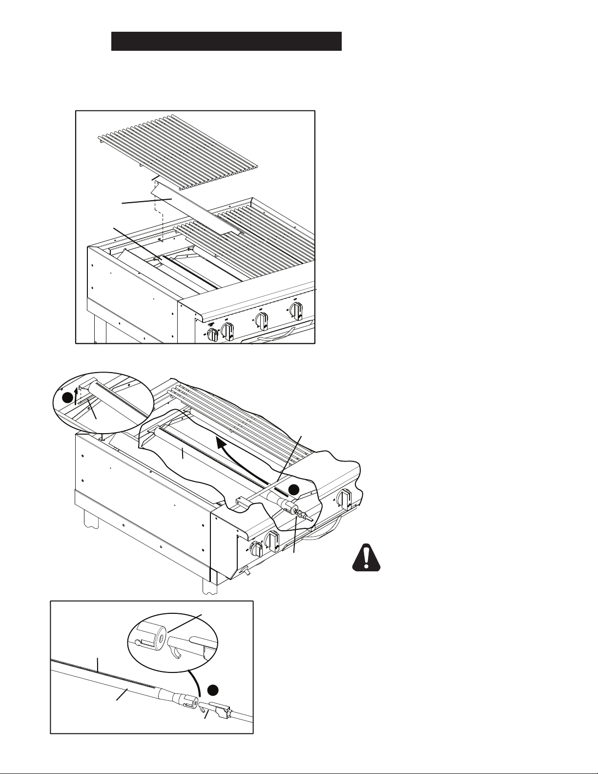
COOKING GRATES & RADIANTS
CLEANING AND INSPECTION
The cooking grates, stainless steel radiants
and the burner can be removed, inspected,
and cleaned as necessary. This is generally
recommended at least once every month of
normal use. The formed hook at the end of
the match lighter rod can be used to lift the
grates up from the grill. Using both hands, lift
up the grate and remove. The grate can be
cleaned with a wire brush and soap solution.
The radiants can be lifted out and inspected
(see illustration). When re-installing the radiants
insert tab into rear slot and place front down
on the alignment stud.
BURNER REMOVAL & CLEANING
Cooking Grates &Radiants can be easily removed for
CAUTION
When re-installing the burner, be sure the burner inlet end
aligns onto the orice as shown in the gure above. The
orice must t straight into the burner inlet hole as shown
and the burner locked in place at the rear with the tab in
the bracket slot. Burner must also sit just below the lighter
tube. Re-install the radiant and grill grates in place above
the burner. Also, at least once a day empty and clean out
the front removable grease pan.
Step 1: The burners can be lifted out by
lifting the end out of the rear slot,
Step 2: Turning to the side while pulling
toward the rear of the grill to remove from
the front orice.
Step 3: Inspect the burner slots, Inlets
& Orice and note their condition. They
can be cleaned using a compressed air
to blow out any debris. If burner slots
are deteriorating or falling apart, replace
burner.
-IMPORTANT-
DO NOT USE COMPRESSED AIR ON
BURNER ORIFICES OR GAS SUPPLY
CONNECTIONS.
Periodically inspect the fuel supply hoses and be sure the
hose is not kinked or wearing in spots. Inspect for cracks or
dried out sections of hose. If there are any cracks or worn
areas, do not operate grill and replace hose immediately.
7
Page 11

DAILY OPERATION (continued)
CLEANING
Clean regularly. Remove cooking grates section to sink for washing use mild detergent and
warm water. Brush out carbonize particles from cooking chamber. Remove and wash grease
pan with mild detergent. Wipe exterior surfaces with detergent and a cloth. A non-abrasive
cleaner can be used on caked areas.
See Accessories Section for any specic instructions on cleaning accessories.
SPIDER WEBS & NEST
Visually inspect the burners & ignitor tube once per year and be sure to visually inspect the inside
inlet venturi & orces for spiders or nests. A spider web in the venturi opening can cause the
following problems:
1. The inability of gas to ow properly into the venturi, resulting in a yellow ame,
no ame, or ashback.
2. The grill does not get up to full temperature. This can also be caused by the
sudden opening of the gas cylinder valve resulting in the actuation of the excess
ow device in the hose/regulator assembly. Turn OFF the gas cylinder valve and
turn the control knob OFF. Wait 15 seconds and slowly turn the LP cylinder valve
ON. Relight the same burner and see if the problem persists. If so, remove the
burner and inspect it for inlet venturi restriction. If there is no restriction, replace
the burner and repeat the lighting steps again by slowly turning on the cylinder
gas valve and lighting the burner. If the burner is still not burning correctly, call
the Star Parts Help Desk at 1-800-807-9054.
STORAGE
DAILY STORAGE
Turn off and disconnect the gas supply when nished using the unit. Once cooled, protect it
with the stainless steal grill grate cover that was provided with the unit or the Hood or Vinyl
Cover Accessory.
LONG TERM STORAGE
Use the following checklist to prepare your unit for long-term storage.
1. Disconnect the gas supply and remove any LP Tank or Tank Caddies that may be on
the unit.
2. Cover any supply hose connectors with caps or plastic bags and secure the ends with
rubber bands or tape, to prevent contamination from occurring.
3. Store LP cylinders outdoors out of reach of children, away from any sources of
heat and ignitors.
4. Clean the inside of your unit.
5. Clean the cooking grids & burners (refer to BURNER REMOVAL & CLEANING) and
lightly oil using cooking oil, and store indoors.
6. Cover the unit, regardless of being stored inside or outside.
8
Page 12
GENERAL ACCESSORY INSTALLATION
IL1100
SHORT BRACKET
LONG BRACKET
IL1086
INITIAL INSPECTION
Remove all packing material from your units accessory and all shipping containers should be checked
for freight damage both visible and concealed. This unit has been tested and carefully packaged to
insure delivery of your unit in perfect condition. If equipment is received in damaged condition, either
apparent or concealed, a claim must be made with the delivering carrier. Read and understand all the
instructions, warnings & labels associated with the unit prior to putting it into operation. Make sure all
individuals associated with its use understand the units operation & safety before they use the unit.
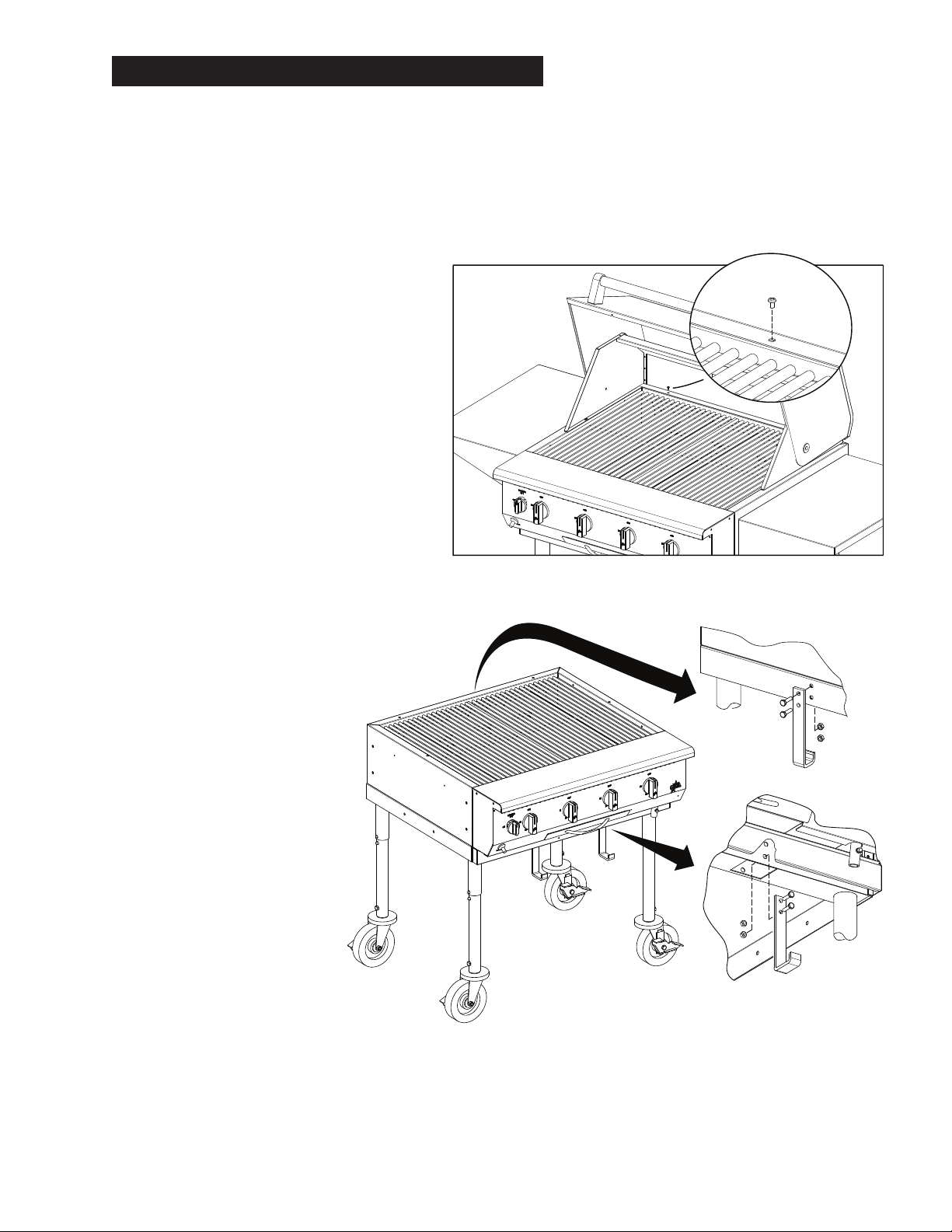
HOOD & WIND GUARD
INSTALLATION
Both the Hood and Wind Guard both install
similarly. Remove the 4 mounting screws
from the top of your grill and set them aside
(2 on the rear and one on each side. Set
the hood and/or wind guard in place and
secure with the mounting screws previously
removed.
REMOVABLE TANK CADDY
These two accessories come complete
and ready to use, once lled (by a qualied
propane gas distributor certied in this
procedure).
INSTALLING LP TANK CART
MOUNTING BRACKETS
The tank hardware package will
have 4 cart mounting brackets
that attaches directly to the grill
frame. The 2 “longer” spaced
brackets will attach to the front
of the grill frame in the mounting
holes provided. The 2 shorter
spaced brackets will attach to
the rear of the frame assembly.
See the illustration showing
bracket attachment. Once
the brackets are secured in
place, the tank caddy is ready
for mounting on the grill frame
brackets.
Hardware for the LP Tank Caddy Mounting Brackets is
supplied with the tank caddy accessory.
9
Page 13

Fill Valve
IL1087
Tank to Caddy
Mounting Bracket
Gas Valve
THUMBSCREW
IL1088
TANK CADDY
LP TANK
REAR SLOT
REAR TANK BRACKET
FRONT TANK BRACKET
GENERAL ACCESSORY INSTALLATION (continued)
LP TANKS
New LP (propane) tanks are supplied
empty in the tank cart and must be
purged of air and lled with propane
per NPGA (National Propane Gas
Association) recommendations prior
to initial use.
INSTALLING LP TANK CADDY
Open and remove the tank cart and hardware package from the carton. The 2-tank caddy (60) will
require 2 hose assemblies attached to the unit. One tank for each the left and right sides.
During use, tanks must be
mounted in the tank caddy and
secured in a horizontal position.
To remove tank from caddy,
remove the ¼-20 thumbscrew
securing the front tank bracket in
place. Tank can be slid out of the
front of the caddy. To reload the
tank into the caddy, slide the tank
back with the brackets located
down until the rear bracket slides
into the rear slot provided in the
tank cart and then position the front
tank bracket in place and secure
tightly using the thumbscrew
previously removed.
Fig. 1, LP Tank installation to Tank Caddy.
CAUTION
Always use the tanks supplied with the tank caddy or a certied 40 lb. horizontal tank DOT marked
LP propane cylinders with mounting brackets. Never over ll tanks and always use supported
and secured in the horizontal position in the tank caddy. Once lled, the LP (propane) tank caddy
can be easily wheeled using the front handle provided on the cart. Position the tank caddy in
place under the grill (with previously installed hanger brackets) with the tank valve end located to
the front of the grill. Be sure grill caster wheels are locked in place using wheel brakes provided
so grill does not move. (See Figure 2).
10
Page 14

IL1089
FRONT
SUPPORT
BRACKET
FRONT
HANGING
BRACKET
IL1080
IL1101
GENERAL ACCESSORY INSTALLATION (continued)
MOUNTING CADDY TO CHARBROILER
Using the cart handles, lift up the front of the tank cart and place the front hanging bracket
on the front support brackets (Fig 3). Move to the back of the grill and using the rear
cart handle, lift up the cart and slide it back into position on the rear hanging brackets.
Hanging brackets will then support the cart rails of the caddy in place on the grill.
Fig. 2, (Above) Lock Wheel
Casters when using grill &
before mounting tank caddy
Fig. 3 (Left) Mounting Tank
Caddy to Front & Rear Mounting Brackets.
CONNECTING GAS SUPPLY LINE
Refer to General Installation Information section for procedures regarding connecting gas
supply and checking for leaks, as well as other important information.
SIDE SHELF INSTALLATION
The side shelf may be installed to either side of
the grill. Remove two of the screws either left
or right, and back off the other two, but do not
remove. Slide the side shelf between the screw
head and grill. Install the two screws previously
removed and tighten all 4 to secure the shelf in
place.
STEAMER & GRIDDLE PLATE
Fig. 4, (Above) Typical Side Shelf Installation.
The steamer and griddle plate can be easily installed by removing one grate section on the
grill and setting the steamer support or griddle in place on the front and rear grate supports.
Never leave water sitting in the steamer, empty any water when nished cooking and clean.
CLEANING
All sections of the steamer can be cleaned using mild detergent and warm water.
SEASONING THE GRIDDLE COOKING SURFACES
FIRST TIME SEASONING
Light Burners under the griddle plate, set the burner setting halfway between low & high.
Depending on the environmental conditions it may take 20 minutes for the plate to reach the
necessary temperature in order to properly season.
1. Bring the grill to necessary temperature and leave it on while doing the next three steps.
2. Brush the cooking surfaces with a release agent. If using an aerosol agent,
rst apply into a cup and then brush onto cooking surface.
3. Let sit for 20 minutes, and then wipe clean using a warm damp cloth.
11
Page 15

20# TANK BRACKET
IL1102
GENERAL ACCESSORY INSTALLATION (continued)
DAILY SEASONING
The griddle plate should not require much
seasoning while in use. In most cases, brush a
light coating of the baking release agent in the
morning and occasionally throughout the day
will be enough to prevent any sticking. It is not
necessary to coat before grilling each item.
20# LP TANK BRACKET
As shown here the 20# LP Tank Bracket can be
easily installed on the side of the unit. Using the
hardware that was provided with the bracket. It
is recommended to place this on the same side
as the manifold connection. On OCB60 models,
there are separate gas connections for the left &
right sides, and this bracket can be mounted on
each end.
NATURAL GAS - CONVERSION KIT
This charbroiler is equipped with xed orice hoods and is shipped from the factory for use with
propane gas. To convert to natural gas, install the burner orice hoods, provided with accessory.
Use the 5” water column natural gas regulator supplied with accessory. A natural gas supply
line can then be attached to the inlet side of the regulator. Supply pressure must be between
5” and 12” water column. Be sure the installation is made by a qualied service technician
knowledgeable in all local codes and the National Fuel Gas Code ANSI Z223.1/NFPA 54.
1. Remove grates, radiants, burners & bullnose.
2. Remove the burner & ignitor tube orice hoods and install the orice hoods supplied.
3. Replace the bullnose, burners, radiants, and grates.
4. Install the Pressure Regulator to the manifold inlet, being sure that the arrow is pointed
in correct location. Attach the conversion label, supplied with the unit, close to the
nameplate.
CHECKING FOR GAS LEAKS - NAT
Check entire piping system for leaks. Soap and water solution or other material acceptable for
the purpose, shall be used in locating gas leakage.
CAUTION
Matches, candle ame or other sources of ignition shall not be used for locating
gas leaks.
12
Page 16

2M-4497-2 10/2010
The foregoing warranty is in lieu of any and all other warranties expressed or implied and constitutes the entire warranty.
FOR ASSISTANCE
Should you need any assistance regarding the Operation or Maintenance of any Star equipment; write, phone, fax or email our Service Department.
In all correspondence mention the Model number and the Serial number of your unit, and the voltage or type of gas you are using.
ALL:
* Pop-Up Toasters
* Butter Dispensers
* Pretzel Merchandisers
(Model 16PD-A Only)
* Pastry Display Cabinets
* Nacho Chip Merchandisers
* Accessories of any kind
* Sneeze Guards
* Pizza Ovens
(Model PO12 Only)
* Heat Lamps
* Pumps-Manual
Visit our Website at: www.star-mfg.com Email: service@star-mfg.com
THOROUGHLY INSPECT YOUR UNIT ON ARRIVAL
This unit has been tested for proper operation before leaving our plant to insure delivery of your unit in perfect condition. However, there are instances in
which the unit may be damaged in transit. In the event you discover any type of damage to your product upon receipt, you must immediately contact the
transportation company who delivered the item to you and initiate your claim with same. If this procedure is not followed, it may affect the warranty status of
the unit.
LIMITED EQUIPMENT WARRANTY
All workmanship and material in Star products have a one (1) year limited warranty on parts & labor in the United States and Canada. Such warranty is limited
to the original purchaser only and shall be effective from the date the equipment is placed in service. Star's obligation under this warranty is limited to the repair
of defects without charge, by the factory authorized service agency or one of its sub-agencies. Models that are considered portable (see below) should be taken
to the closest Star service agency, transportation prepaid.
> Star will not assume any responsibility for loss of revenue.
> On all shipments outside the United States and Canada, see International Warranty.
* The warranty period for the JetStar six (6) ounce & Super JetStar eight (8) ounce series popcorn machines is two (2) years.
* The warranty period for the Chrome-Max Griddles is ve (5) years on the griddle surface. See detailed warranty provided with unit.
* The warranty period for Teon/Dura-Tec coatings is one year under normal use and reasonable care. This warranty does not apply if damage occurs to
Teon/Dura-Tec coatings from improper cleaning, maintenance, use of metallic utensils, or abrasive cleaners, abrasive pads, product identiers and
point-of-sale attachments, or any other non-food object tha comes in continuous contact with the roller coating. This warranty does not apply to the
“non-stick” properties of such materials.
> This warranty does not apply to "Special Products" but to regular catalog items only. Star's warranty on "Special Products" is six (6) months on parts
and ninety (90) days on labor.
> This warranty does not apply to any item that is disassembled or tampered with for any purpose other than repair by a Star Authorized Service Center or
the Service Center's sub-agency.
> This warranty does not apply if damage occurs from improper installation, misuse, wrong voltage, wrong gas or operated contrary to the Installation and
Operating instructions.
> This warranty is not valid on Conveyor Ovens unless a "start-up/check-out" has been performed by a Factory Authorized Technician.
PARTS WARRANTY
Parts that are sold to repair out of warranty equipment are warranted for ninety (90) days. The part only is warranted. Labor to replace the part is chargeable to
the customer.
SERVICES NOT COVERED BY WARRANTY
PORTABLE EQUIPMENT
Star will not honor service bills that include travel time and mileage charges for servicing any products considered "Portable" including items listed below.
These products should be taken to the Service Agency for repair:
1. Travel time and mileage rendered beyond the 50 mile radius limit
2. Mileage and travel time on portable equipment (see below)
3. Labor to replace such items that can be replaced easily during a daily cleaning
routine, ie; removable kettles on fryers, knobs, grease drawers on griddles, etc.
4. Installation of equipment
5. Damages due to improper installation
6. Damages from abuse or misuse
7. Operated contrary to the Operating and Installation Instructions
8. Cleaning of equipment
9. Seasoning of griddle plates
10. Voltage conversions
11. Gas conversions
12. Pilot light adjustment
13. Miscellaneous adjustments
14. Thermostat calibration and by-pass adjustment
15. Resetting of circuit breakers or safety controls or reset buttons
16. Replacement of bulbs
17. Replacement of fuses
18. Repair of damage created during transit, delivery, &
installation OR created by acts of God
* The Model 510FD Fryer.
* The Model 526TOA Toaster Oven.
* The Model J4R, 4 oz. Popcorn Machine.
* The Model 518CMA & 526CMA Cheese Melter.
* The Model 12MC & 15MC & 18MCP Hot Food Merchandisers.
* The Model 12NCPW & 15NCPW Nacho Chip/Popcorn Warmer.
* All Hot Dog Equipment except Roller Grills & Drawer Bun Warmers.
* All Nacho Cheese Warmers except Model 11WLA Series Nacho Cheese Warmer.
* All Condiment Dispensers except the Model HPD & SPD Series Dispenser.
* All Specialty Food Warmers except Model 130R, 11RW Series, and 11WSA Series.
* All QCS/RCS Series Toasters except Model QCS3 & RCS3 Series.
* All Fast Steamer Models except Direct Connect Series.
13
Page 17

20
21
22
23
24
21
thru
24
Are sold with Accessories:
30” & 60” Removable Tank Caddies
A
1
2
3
4
5
6
7
8
9
10
11
12
13
14
15
15
16
17
18
25
26
27
19
STAR MANUFACTURING INTERNATIONAL, INC.
CERTAIN INSTANCES MAY NOT BE AVAILABLE
ILLUSTRATIVE PURPOSES ONLY AND IN
SOME ITEMS ARE INCLUDED FOR
MODEL: OCB
SK2163 REV. -
2/13/06
No reproduction or disclosure of its
to Star Manufacturing International, Inc.
This drawing contains information confidential
contents is permitted.
14
Page 18

PARTS LIST August 16, 2011, Rev. A
MODEL
Fig No Part No QTY Desc Model
1 2B-Z9213
2 H5-Z9237
3 H5-Z9240
4 H5-Z9256
6 H5-OCG0008 1 WRAPPER ASSY OCB30
7 H5-OCG0005 1 BOTTOM FRAME ASSY. OCB30
8 H5-OCG0007 1 FRONT GRATE SUPPORT ASSY OCB30
9 H5-Z9242
10 H5-Z9241
11 H5-Z9236 1 ORFICE BRACKET OCB30
12 H5-OCG0003 1 BULLNOSE ASSY, OCB30
13
14
15 H5-Z9245
16 H5-Z9235
17 H5-Z9234
18 2R-Z6726
19 2C-Z6744
20 2V-Z9214 1 SET CASTER LEG (SET OF 4)
21 2C-Z5555 8 BOLT, 1/4-20 X .75” HEX S.S. included in Caddy Accessory
22 2A-Z9255 2 CADDY HANGING BRKT LONG-FRONT included in Caddy Accessory
23 2C-T1009 8 NUT, 1/4-20 HEX STL NP included in Caddy Accessory
24 2A-Z9254 2 CADDY HANGING BRKT SHORT-REAR included in Caddy Accessory
25 2R-Z6726 1 HANDLE, GRILL GRATE COVER
26 H5-Z9275
27 2J-Z9289
H5-Z9238
H5-Z9239 OCB60
H5-Z9278
H5-Z9279 OCB60
2
4 OCB60
4
8 OCB60
1
2 OCB60
1
2 OCB60
2
4 OCB60
1
2 OCB60
1 FRONT PANEL
1 LOWER FRONT APPEARANCE BRKT.
2
4 OCB60
1
2 OCB60
1
2 OCB60
1
2 OCB60
2
4 OCB60
1
2 OCB60
1
2 OCB60
OUTDOOR CHARBROILER GRILL, OCB30 & OCB60
GRILL GRATE
RADIANT
REAR BURNER SUPPORT BRACKET
PAN SHIELD
SUPPORT BRACKET, IGNITOR TUBE
IGNITOR - BOX
PAN SUPPORT BRKT
PAN - GREASE
PAN - FACEPLATE
HANDLE, PAN
SCREW, 8-32 X 5/16 RHP SS
GRILL GRATE COVER
HOSE-REGULATOR ASSY
OCB30
OCB30
OCB30
OCB30
OCB30
OCB30
OCB30
OCB30
OCB30
OCB30
OCB30
OCB30
OCB30
OCB30
OCB30
1
IMPORTANT: WHEN ORDERING, SPECIFY VOLTAGE OR TYPE GAS DESIRED PAGE
1
INCLUDE MODEL AND SERIAL NUMBER OF
Some items are included for illustrative purposes only and in certain instances may not be available.
Star Manufacturing International, Inc.
15
Page 19

1
2
3
4
5
6
7
8
9
11
10
12
13
14
15
STAR MANUFACTURING INTERNATIONAL, INC.
CERTAIN INSTANCES MAY NOT BE AVAILABLE
ILLUSTRATIVE PURPOSES ONLY AND IN
SOME ITEMS ARE INCLUDED FOR
MODEL: OCB-MANIFOLD
SK2161 REV. A
6/8/06
No reproduction or disclosure of its
to Star Manufacturing International, Inc.
This drawing contains information confidential
contents is permitted.
16
Page 20

PARTS LIST August 16, 2011, Rev. A
MODEL
Fig No Part No QTY Desc Model
1 2F-Z9200
2 2J-Z5671
3 2V-Z6939
4 2K-Z9221 1 MANIFOLD OCB30
6 2R-Z4997
7 2R-Z9212
8 2J-Z7195
9 2K-Z6942
10 2J-Z9208
11 2K-Z6941
12
13 2J-Z6908
14 2K-Z6943
OUTDOOR CHARBROILER GRILL MANIFOLD, OCB30 & OCB60
4
8 OCB60
4
8 OCB60
5
10 OCB60
4
8 OCB60
1
2 OCB60
1
2 OCB60
1
2 OCB60
1
2 OCB60
1
2 OCB60
2F-Z9201
2F-Z9202 IGNITOR TUBE, 3/8” LT OCB60
1
1
2 OCB60
1
2 OCB60
BURNER 1 1/4” Dia.
ORIFICE # 56
VALVE HI-LO
KNOB
KNOB, IGNITOR TUBE RED
SWITCH, IGNITOR
FITTING 3/8-27 MALE X 1/4
ORFICE, IGNITOR
FITTING 3/8-27 FEMALE X 1/4
IGNITOR TUBE, 3/8” RT OCB30
IGNITOR - STRAIGHT
GAS LINE 1/4”DIA X 8”L
OCB30
OCB30
OCB30
OCB30
OCB30
OCB30
OCB30
OCB30
OCB30
OCB30
OCB30
1
IMPORTANT: WHEN ORDERING, SPECIFY VOLTAGE OR TYPE GAS DESIRED PAGE
1
INCLUDE MODEL AND SERIAL NUMBER OF
Some items are included for illustrative purposes only and in certain instances may not be available.
Star Manufacturing International, Inc.
17
Page 21

OCB-WG30
OCB-H30
OCB-S15
OCB-G15
OCB-SHELF
OCB-TB20
OCB-TC60
OCB-CKNAT
STAR MANUFACTURING INTERNATIONAL, INC.
CERTAIN INSTANCES MAY NOT BE AVAILABLE
ILLUSTRATIVE PURPOSES ONLY AND IN
SOME ITEMS ARE INCLUDED FOR
MODEL: OCB-ACCESSORIES
SK2167 Rev. A
6/07/06
No reproduction or disclosure of its
to Star Manufacturing International, Inc.
This drawing contains information confidential
contents is permitted.
18
Page 22

PARTS LIST August 16, 2011, Rev. A
MODEL
ACCESSORIES FOR OUTDOOR CHARBROILER GRILL
Number
Key
Number
OCB-CKNAT NATURAL GAS CONVERION KIT
2J-Z9207 2 PRESSURE REGULATOR RV47
2J-Z9209 2 ORFICE IGNITOR TUBE # 59
2J-Z9288 8 ORFICE #49
2M-Z7528 1 LABEL “CONVERTED TO NAT”
OCB-G15 GRIDDLE PLATE
H5-OCG0012 1 GRIDDLE PLATE ASSY. 15” W
OCB-H30 HOOD
2C-Z6932 2 ACORN NUT 3/8”
2C-Z6933 4 HEX BOLT, 1/4-20X1”
2C-Z9244 2 PIVOT BOLT, HOOD
2I-Z6924 2 HANDLE INSULATOR
2P-Z6922 2 HANDLE END CAP
2R-Z6988 1 HANDLE
2T-Z9247 1 TEMPERATURE GAUGE
H5-OCG0009 1 HOOD ASSY
H5-Z9251 1 BACK, HOOD SUPPORT
H5-Z9252 1 RIGHT SIDE HOOD SUPPORT
H5-Z9253 1 LEFT SIDE, HOOD SUPPORT
OCB-S15 STEAMER
2D-Z9282 1 WATER PAN FULL SIZE 4”
2D-Z9283 1 PERFORATED PAN F.S. 2 1/2”
2D-Z9284 1 PAN COVER FULL SIZE, NO HANDLE
H5-Z9281 1 STEAMER BODY 15” W
OCB-SHELF SIDE SHELF
H5-Z9273 1 SIDE SHELF
OCB-TB20 20# TANK BRACKET
2C-T1009 2 NUT 1/4-20 HEX STL NP
2C-Z6927 2 1/4-20X1/2”L PH PAN HD
H5-Z9292 1 TANK BRACKET, 20# LP
OCB-TC30 TANK CADDY 30"
2A-Z9254 2 CADDY HANGING BRKT. SHORT
2A-Z9255 2 CADDY HANGING BRKT. LONG
2A-Z9265 2 HANDLE CADDY
2C-Z0280 1 THUMB SCREW
2P-Z6770 2 CASTER RIGID 3 1/2”
2P-Z6771 2 CASTER SWIVEL 3 1/2”
2V-Z9259 1 40# HORIZONTAL LP TANK
H5-OCG0010 1 TANK CADDY BODY ASSY
H5-Z9266 2 CADDY SUPPORT BRKT
H5-Z9269 1 REAR TANK HOLD DOWN BRKT
OCB-TC60 TANK CADDY 60"
2A-Z9254 2 CADDY HANGING BRKT. SHORT
2A-Z9255 2 CADDY HANGING BRKT. LONG
2A-Z9258 2 HANDLE CADDY
2C-Z0280 2 THUMB SCREW
2P-Z6770 2 CASTER RIGID 3 1/2”
2P-Z6771 2 CASTER SWIVEL 3 1/2”
2V-Z9259 2 40# HORIZONTAL LP TANK
H5-OCG0011 1 TANK CADDY BODY ASSY
H5-Z9260 2 CADDY SUPPORT BRKT
H5-Z9263 1 REAR TANK HOLD DOWN BRKT
OCB-WG30 WIND GUARD
H5-Z9276 1 WIND GUARD
Part
Number
Per
Unit
Description and Model Designation
Some items are included for illustrative purposes only and in certain instances may not be available.
Star Manufacturing International, Inc.
19
PAGE
OF
1
1
Page 23

Page 24

Page 25

Page 26

12
20 livres crochet
du réservoir
IL1136
d’inammation pour effectuer un essai d’étanchéité
N’utilisez pas les allumettes, la amme d’une bougie, ou d’autres sources
MISE EN GARDE
acceptable pour cet essai, peut être utiliser pour effectuer un essai d’étanchéité.
Vérier le circuit de tuyauteries entier pour les fuites. Une solution savonneuse or d’autre matériel
Pour effectuer un essai d’étanchéité – gaz naturel
plaque-marque.
vers la zone correcte. Afchez l’étiquette à conversion, fourni avec l’appareil, près de la
4. Installez le régulateur de pression à l’entrée du collecteur, soyez sûr que la èche vise
3. Remplacez le bouchon de conduite, les brûleurs, les radiants et les grilles.
2. Enlevez le brûleur et l’accessoire GPL et montez l’accessoire fourni.
1. Enlevez tous les grilles, les radiants, les brûleurs et le bouchon de conduite.
combustibles ANSI Z223.1/NFPA 54.
est effectuée par un technicien qui connaît tous les codes locaux et le Code national des gaz
d’alimentation doit être entre 5 po et 12 po de colonne d’eau. Assurez-vous que l’installation
l’accessoire. Une conduite du gaz naturel peut être attachée à l’entrée du régulateur. La pression
avec les accessoires. Utilisez le 5 po de colonne d’eau régulateur du gaz naturel fourni avec
avec du gaz propane. Pour convertir au gaz naturel, montez les accessoires du brûleur, fourni
Ce charbroiler est équipé avec un accessoire GPL et il est transporté de l’usine pour l’utilisation
GAZ NATUREL – JEU DE CONVERSION
chaque côté.
et à gauche, et ce crochet peut être monté sur
raccords de gaz différents pour les côtés à droit
connecteur. Sur les modèles OCB60 il y a les
de le placer sur le même côté du raccord du
fourni avec le crochet. Il est recommandé
le côté de l’appareil. Utilisez le jeu de pièces
GPL 20# (9.1kg) peut être facilement monté sur
Comme le démontre ici le crochet du réservoir
GPL
20# (9.1 kg) CROCHET DU RÉSERVOIR
pas nécessaire de napper avant chaque grillage.
pendant la journée de temps en temps. Il n’est
une couche douce d’un antiadhésif au matin et
Généralement, pour prévenir le collage, brossez
d’assaisonnement pendant l’utilisation.
Le gril ne doit pas requérir beaucoup
ASSAISONNEMENT JOURNALIER
INSTALLATION GENERALE DES ACCESSOIRES (SUITE)
Page 27

IL1135
Crochet
avant
Support
d’accrochage
avant
IL1080
IL1101
tablette latérale
11
Fig. 4(Au-dessus) Installation typique de la
3. Laissez pour vingt minutes, ensuite essuyez avec un chiffon chaud et humide.
agent d’aérosol, mettez dans une tasse et puis brossez sur la surface de cuisson.
2. Brossez les surfaces de cuisson avec un agent antiadhésif. Si vous utilisez un
étapes suivantes.
1. Chauffez la grille à la température nécessaire et laissez pendant que vous faites les
température nécessaire an d’assaisonner correctement.
Selon les conditions d’ambiance, il peut prendre vingt minutes pour le gril d’atteindre la
Allumez les brûleurs sous le gril, réglez le réglage du brûleur entre bas et haut (low et high).
ASSAISONNEMENT INITIAL
ASSAISONNEMENT LES SURFACES DE CUISSON DU GRIL
chaude.
Toutes les sections du four à vapeur peuvent être nettoyées avec un détergent doux et de l’eau
NETTOYAGE
vapeur, videz l’eau lorsque vous nissez de cuire et nettoyez.
gril en place sur les supports de grille arrière et avant. Ne laissez jamais d’eau dans le four à
Enlevez une section de la grille sur le barbecue et en mettant le support du four à vapeur ou le
Le four à vapeur et le gril peut être facilement montés.
FOUR À VAPEUR ET GRIL
serrez toutes les 4 vis pour xer le panneau en place.
de la vis et le barbecue. Vissez les 2 vis déjà enlevées et
démontez pas. Glissez le panneau latéral entre la tête
droit, et dévissez un peu les autres 2 vis, mais ne les
barbecue. Démontez deux des vis soit à gauche soit à
Le panneau latéral peut être monté de chaque côté du
INSTALLATION DU PANNEAU LATÉRAL
d’alimentation de gaz et les essais d’étanchéité et d’autres renseignements importants.
Voir la section d’Information Générale d’Installation pour les procédures concernant le branchement
BRANCHER LA CONDUITE DE GAZ
avant et arrière
iot aux supports d’accrochage
Fig. 3 (A gauche) Monter le char-
chariot
barbecue et avant de monter le
roulettes pendant l’utilisation du
Fig 2. (Au-dessus) Verrouillez les
Les supports d’accrochage supporteront les tringles du chariot en place sur le barbecue.
poignée arrière, levez le chariot et glissez-le en position sur les support d’accrochage arrières.
avant sur les crochets de support avant (Fig. 3) Bougez à l’arrière du barbecue et en utilisant la
En utilisant les poignées du chariot, soulevez l’avant du chariot et placez le support d’accrochage
MONTER LE CHARIOT AU CHARBROILER
INSTALLATION GÉNÉRALE (LA SUITE)
Page 28

10
Soupape
d’alimentation
IL1133
Crochet pour
monter le
réservoir au chariot
Soupape
à gaz
Vis à serrage
à main
IL1134
Chariot
Réservoir GPL
Ouverture arrière
Crochet du réservoir arrière
Crochet du réservoir avant
les roulettes et pour prévenir tout mouvement. (Voir la gure 2)
située vers l’avant du barbecue. Assurez-vous d’utiliser les freins de roue fournis pour verrouiller
barbecue (avec les supports d’accrochage déjà installés)avec le bout de la soupape de réservoir
(propane) avec la poignée fournie avec le chariot. Placez le chariot de réservoir au-dessous le
dans le chariot. Une fois remplie, vous pouvez facilement pousser le chariot de réservoir GPL
Ne remplissez jamais excessivement les réservoirs et utilisez toujours en position horizontale
spécications des bouteilles de gaz GPL du département des Transports des États-Unis (DOT)..
certié de 40 lbs (18.1 kg). La bouteille de gaz GPL utilisée doit être identiée conformément aux
Utilisez toujours les réservoirs fournis avec le chariot de réservoir ou un réservoir horizontal
AVERTISSEMENT
avez déjà devisée.
la vis à serrage à main que vous
Fig 1. Installation du réservoir GPL au chariot
place et xez étroitement avec
le crochet du réservoir avant en
dans le chariot, puis positionnez
dedans l’ouverture arrière fournie
que les crochets arrières glissent
crochets situés en bas jusqu’à ce
le réservoir en arrière avec les
le réservoir dans le chariot, glissez
le devant du chariot. Pour remettre
réservoir peut être glissé dehors
le crochet du réservoir avant. Le
¼-20 vis à serrage à main qui xe
réservoir du chariot, devissez la
horizontale. Pour démonter le
chariot et fixés en position
doivent être montés dans le
Pendant l’utilisation les réservoirs
pour le côté gauche.
requerra 2 ensembles de tuyau attachés à l’appareil. Un réservoir pour le côté droit et un réservoir
Ouvrez et enlevez le chariot de réservoir et le jeu de pièces de la caisse. Le chariot à 2 réservoirs
INSTALLATION DU CHARIOT DE RÉSERVOIR GPL
l’utilisation.
propane) les recommandations avant
(Association Nationale du gaz
NPGA
le réservoir avec du propane suite
vider le réservoir d’air et remplissez
chariot de réservoir et vous devez
(propane) sont fournis vides dans le
Les nouveaux réservoirs GPL
RESERVOIRS GPL
INSTALLATION GENERALE DES ACCESSOIRES (SUITE)
Page 29

9
IL1100
crochet court
crochet long
IL1132
fourni avec l’accessoire du chariot.
Le jeu de pièces pour les Crochets du Chariot du Réservoir GPL est
supports de l’encadrement.
est prêt pour monter sur les
en place, le chariot du réservoir
fois que les supports sont xés
l’attachement du support. Une
Voir l’illustration qui démontre
l’ensemble de l’encadrement.
plus courts xeront à l’arrière de
fournis. Les 2 supports qui sont
dans les trous de montage
l’encadrement du barbecue
longs fixeront à l’avant de
Les 2 supports qui sont plus
encadrement du barbecue.
qui fix ent directem ent au
aura 4 supports de montage
Le jeu de pièces du réservoir
LP
DU CHARIOT DU RÉSERVOIR
SUPPORTS DE MONTAGE
I N S T A L L AT I O N D E S
certié du gaz propane).
à utiliser une fois rempli, (par un distributeur
Ces 2 accessoires viennent complets et prêts
DÉMONTABLE
CHARIOT DU RÉSERVOIR
que vous avez enlevées.
et/ou la garde en place et xez avec les vis
il y a une sur chaque côté. Mettez le couvercle
dessus du barbecue (2 se trouve à l’arrière et
pareillement. Enlevez les 4 vis de montage du
Vous installez le couvercle et la garde
DE LA GARDE-VENT
INSTALLATION DU COUVERCLE ET
utilisent l’appareil.
les personnes qui utilisent l’appareil comprennent l’utilisation et la sécurité de l’appareil avant qu’ils
avertissements et les étiquettes associés à l’appareil avant d’utiliser l’appareil. Assurez-vous que toutes
devez réclamer une demande avec le transporteur. Lisez et comprenez tous les renseignements, les
d’un appareil à l’état neuf. Si vous recevez l’appareil endommagé – apparent ou non apparent, vous
dommage de transport soit apparent ou non apparent. L’appareil a été essayé pour assurer une livraison
Enlevez tout matériel d’emballage des accessoires et assurez-vous de vérier les caisses pour le
VERIFICATION INITIALE
INSTALLATION GENERALE DES ACCESSOIRES
Page 30

8
6. Couvrez l’appareil bien que vous le reposiez à l’intérieur ou à l’extérieur.
BRÛLEURS) et lubriez avec de l’huile de cuisson et reposez à l’intérieur.
5. Nettoyez les grilles de cuisson et les brûleurs (voir ENLEVER ET NETTOYER LES
4. Nettoyez l’intérieur de l’appareil.
loin des sources d’inammation ou de chaleur.
3. Entreposez les bouteilles de propane à l’extérieur hors de la portée des enfants,
prévenir la contamination.
plastique et xer les bouts avec des rubans élastiques ou des rubans adhésifs pour
2. Couvrez des raccords des tuyaux d’alimentation avec les couvercles ou les sacs en
réservoir qui sont sur l’appareil.
1. Débranchez l’alimentation en gaz et enlevez tout réservoir GPL ou chariot de
terme.
Utilisez la liste de vérication suivante pour préparer l’appareil pour l’entreposage à long
ENTREPOSAGE A LONG TERME
l’appareil et protégez-le avec la couverture fournie avec l’appareil.
Fermez et coupez l’alimentation en gaz lorsque vous nissez d’utiliser l’appareil. Laissez refroidir
ENTREPOSAGE JOURNALIER
ENTREPOSAGE
pas correctement, appelez Star Parts Help Desk à 1-800-807-9054.
lentement le robinet de la bouteille de gaz et en allumant le brûleur. Si le brûleur ne brûle
n’y a aucune obstruction, remontez le brûleur et reprenez les étapes d’allumage en ouvrant
problème persiste. Si oui, démontez le brûleur et vériez si le tube de venturi est obstrué. Sil
lentement le robinet de la bouteille de gaz GPL. Rallumez le même brûleur et vériez si le
le bouton de commande sur la position OFF (arrêt). Attendez 15 secondes et OUVREZ
bit dans l’ensemble tuyau/régulateur. FERMEZ le robinet de la bouteille de gaz et tournez
une ouverture soudaine de robinet de la bouteille de gaz, ce qui enclenche le limiteur de
2.Le barbecue n’atteint pas sa température maximale. Cela peut également être causé par
jaune, une absence de amme ou un retour de amme.
1. L’obstruction de la circulation de gaz dans le tube de venturi, ce qui produit une amme
à l’intérieur du tube de venturi peut caser les problèmes suivants :
présence d’araignées ou de nids à l’intérieur du tube de venturi et les orices. Une toile d’araignée
Vériez visuellement les brûleurs et l’allumeur une fois par an en vous assurant de vérier la
Les Toiles d’Araignées et les Nids
Les Toiles d’Araignées et les Nids
nettoyage.
Voir la section d’accessoires pour les instructions spéciques pour les accessoires de
Un nettoyeur non abrasif peut être utilise sur les sections très sales.
le plateau d’eau avec un détergent doux. Essuyez les parois avec du détergent et un chiffon.
doux et de l’eau chaude. Brossez les particules de la chambre de cuisson. Enlevez et nettoyez
Nettoyez régulièrement. Enlevez la section des grilles de cuisson et nettoyez avec un détergent
NETTOYAGE
UTILISATION JOURNALIERE (SUITE)
Page 31

Brûleur
Radiants
Grilles de cuisson
IL1129
brûleur
IL1131
Ouvertures
du brûleur
Air comprimé
3
Entrée du brûleur
IL1130
2
Tube de l’allumeur
Brûleur
Orifice
1
Ouverture arrière
MISE EN GARDE
RACCORDS DES CONDUITES DE GAZ
LES ORFICES DES BRÛLEURS OU LES
N’UTILISEZ PAS D’AIR COMPRIME SUR
-IMPORTANT-
brûleur.
du brûleur sont dégénérés, remplacez le
pour soufer aucun résidu. Si les orices
les nettoyer en utilisant l’air comprimé
remarquez leur condition. Vous pouvez
brûleurs, les entrées et les orices et
Étape 3 : Vériez les ouvertures des
7
le barbecue et remplacez le tuyau immédiatement.
trouvez des ssures ou des sections desséchées, n’utilisez pas
pour les ssures ou les sections desséchées du tuyau. Si vous
assurez-vous que le tuyau n’est pas tortillé ou usé. Vériez
Vériez régulièrement les tuyaux de l’alimentation du gaz et
nettoyez le plateau de graisse au moins une fois par jour.
et les grilles en place au-dessus le brûleur. D’ailleurs, videz et
doit rester juste au-dessous le tube éclair. Remontez le radiant
à l’arrière avec l’onglet dans l’ouverture du crochet. Le brûleur
brûleur comme montré et le brûleur doit être verrouillé en place
dans la gure au-dessus. L’orice doit entré dans l’entrée du
de l’entrée du brûleur aligne sur l’orice comme le démontre
Lorsque vous remontez le brûleur, assurez-vous que l’extrémité
enlever de l’orice avant.
tirez vers l’arrière du barbecue pour
Étape 2: Balancez pendant que vous
Les grilles de cuisson et les radiants peuvent être facilement enlever pour le nettoyage.
levant l’extrémité hors de l’ouverture arrière.
Étape 1: Les brûleurs peuvent être soulevés en
ENLEVER ET NETTOYER LES BRÛLEURS
et mettez l’avant sur le goujon d’alignement.
remontez les radiants, insérez dans l’ouverture arrière
radiants et les vérier (voir l’illustration). Lorsque vous
solution d’eau savonneuse. Vous pouvez soulever les
Nettoyez la grille avec une brosse métallique et une
les deux mains, soulevez la grille et déplacez-le.
utilisé pour soulever les grilles du barbecue. En utilisant
Le crochet à l’extrémité du tige d’allumage peut être
moins une fois chaque mois pour l’utilisation normale.
le cas échéant. En général, cela est recommandé au
et le brûleur peuvent être enlevés, vériés et nettoyés
Les grilles de cuisson, les radiants d’acier inoxydable
NETTOYAGE ET VERIFICATION
LES GRILLES DE CUISSON ET LES RADIANTS
pour la sécurité.
l’appareil pour quelque temps, débranchez les conduites de gaz GPL (propane) du réservoir
contraire aux aiguilles d’une montre à la position OFF. Si vous prévoyez de ne pas utiliser
Pour fermer l’appareil tournez tous les boutons des brûleurs et le bouton rouge dans le sens
FERMER L’APPAREIL
UTILISATION JOURNALIERE (SUITE)
Page 32

6
2
1
IL1085
IL1114
(Fig. 2)
pour allumer le tube d’allumeur de 3/8 po D.
attachée à la baguette, l’insérez entre les grilles
(marche) et en utilisant la amme d’une allumette
aux aiguilles d’une montre à la position « ON »
et tournez le bouton rouge dans le sens contraire
allumette pour allumer le tube d’allumeur. Enfoncez
d’allumage fournie avec l’appareil pour tenir une
position « OFF » (arrêt) et utilisez la baguette
plusieurs essais, tournez le bouton rouge à la
4. 4. Si l’allumeur n’allume pas le brûleur après
d’allumeur (Figure 1).
l’allumeur plusieurs fois pour allumer le petit tube
voulez allumer. Il peut être nécessaire d’enfoncer
(marche) et enfoncez l’allumeur sur le côté vous
aux aiguilles d’une montre à la position « ON »
3. Tournez le bouton rouge dans le sens contraire
vous voulez allumer.
laisser la circulation de gaz au côté du barbecue
le sens contraire aux aiguilles d’une montre pour
2. Ouvrez lentement le robinet du réservoir GPL dans
les brûleurs devraient allumer.
et tournés dans le sens contraire aux aiguilles d’une montre à la position « HI » (feu vif) et
l’appareil. Lorsque le tube éclair est allumé, les boutons de brûleur (noir) peuvent être enfoncés
n’allume pas, coupez l’alimentation en gaz, attendez 5 minutes et essayez d’allumer encore
5. Vériez que la longueur entière du tube éclair est allumé et qu’il fonctionne. Si le tube éclair
pas.
allumer le tube si le bouton de l’allumeur ne marche
Fig.2 Utilisez la baguette avec une allumette pour
de l’allumeur.
appuyez sur le bouton de l’allumeur pour allumer le tube
Fig. 1 Tournez le bouton à la position ON (marche) et
l’ouvrir.
Si l’appareil a un couvercle, assurez-vous de
robinets du réservoir GPL (en position «OFF»).
1. Assurez-vous de fermer et xer en place les
dehors la conduite de gaz et le collecteur.
prendre plus de temps parce qu’il faut vider l’air
Remarque : Le premier allumage de l’appareil peut
étapes d’allumage 1 à 5 au-dessus.
le barbecue et « lentement » ouvrez la soupape de commande de réservoir de gaz. Suivez les
amme réduite. Si cela arrive, vériez que les réservoirs ne sont pas vides ou hors gaz. Fermez
une condition d’une circulation excessive et causerait les brûleurs de fonctionner avec une
de réduire. C’est une caractéristique de sécurité conçu pour limiter la circulation de gaz sous
excessif du gaz dans le raccord du réservoir qui peut causer la circulation de gaz au collecteur
Remarque : Il est nécessaire d’ouvrir les robinets du réservoir lentement pour prévenir un débit
ALLUMAGE DU BARBECUE
barbecue repose sur une surface plate.
inammables, d’essence ou d’autres vapeurs ou liquides inammables. Assurez-vous que le
zone ouverte autour du barbecue et de son enceinte, et gardez l’espace exempt de matériaux
et elle peut émettre des ammes dans des conditions extrêmes. Maintenez en tout temps une
inammable à proximité ou au-dessus du barbecue. La sortie de ventilation peut être très chaude
maison ni de toute autre structure inammable. Ne placez pas de parasols ni tout autre article
comme l’exposition au vent et le niveau de circulation. Ne placez pas le barbecue près d’une
Au moment de choisir l’emplacement qui convient à votre barbecue, tenez compte de facteurs
CHOIX DE L’EMPLACEMENT
UTILISATION JOURNALIERE
Page 33

IL1127
90°
OCB30
Ensemble du
régulateur
Orifice de
sortie
L’entrée du
barbecue
LES CHARBROILERS SONT CHAUDS!DAILY
Brûleur
Obturateur
d’air
IL1128
Vis
Débit d’air
Débit d’air
5
MISE EN GARDE
refroidir, lorsque vous faites ces réglages.
et dure paraît. Fermez l’appareil et laissez
jaunes disparaissent et une amme bleue
lentement les entrées à tel point que les bouts
avec les bouts lumineux, ensuite augmentez
pour donner une amme bleue et douce
entrées des obturateurs d’air sur les brûleurs
obturateurs d’air, diminuez lentement les
le bouchon de conduite pour exposer les
2. Si nécessaire, fermez l’appareil, enlevez
: comme le démontre dans la gure 2.
Allumez l’appareil et réglez sur HIGH. Remarque
1. Enlevez les grilles de cuisson et les radiants.
un réglage est requis, suivez ces étapes:
à l’usine et ne devraient pas exigés une réglage. Si
Les obturateurs d’air de cet appareil ont été réglés
amme correcte.
Fig. 2 : Régler l’obturateur d’air du brûleur pour atteindre une
l’appareil
Réglage du brûleur
Fig 1. Brancher l’ensemble du régulateur du réservoir GPL à
essai.
N’utilisez pas les allumettes, les bougies ou d’autre source of ignition pour cet
MISE EN GARDE
l’utilisation.
PAS LE BARBECUE AVEC AUCUNE FUITE. S’il n’y a pas de fuites, l’appareil est prêt pour
ou appelez votre compagnie de gaz locale ou votre détaillant pour le service. N’UTILISEZ
S’il y a une fuite, fermez immédiatement le robinet de gaz et resserrez le raccord avec la fuite,
Observez tous les raccords pour les bulles pour déterminer s’il y a une fuite.
d’étanchéité) et brossez tous les raccords de gaz. Ouvrez lentement le robinet de réservoir GPL.
d’eau savonneuse (ou une solution d’essai
et tous les brûleurs. Utilisez une solution
OFF) tous les réservoirs GPL (propane)
Assurez-vous de fermer (mettre en position
ESSAI D’ÉTANCHÉITÉ
inégale.
varier si vous le reposez sur une surface
Le fonctionnement de l’appareil peut
vous de le reposer sur une surface plate.
Avant l’utilisation de l’appareil, assurez-
NIVELER L’APPAREIL
de coté droit au réservoir droit.
montera au réservoir gauche et le tuyau
Sur le modèle 60, le tuyau de coté gauche
du barbecue avec une clé.
TROP. (Fig. 1) Fixez l’autre bout à l’entrée
l’orice de sortie à main. NE SERREZ
la conduite de gaz. Serrez le raccord à
pas tortiller ou endommager le tuyau de
de type 1 en place. Assurez-vous de ne
(18.1Kg). Enlevez le garde de poussière de l’orice de sortie et vissez soigneusement le raccord
L’ensemble régulateur/tuyau du barbecue peut être xé à l’orice de sortie du réservoir 40 lbs
BRANCHER LA CONDUITE DE GAZ
INSTALLATION GENERALE (suite)
Page 34

4
IL1126
Douille du pied
Ensemble de
la roulette
Verrouillage
Enlever avant de placer
sur le côté arrière
IL1080
prévenir tout mouvement. (Voir la gure 2).
Assurez-vous d’utiliser les freins de roue fournis pour verrouiller les roulettes et pour
installés)avec le bout de la soupape de réservoir située vers l’avant du barbecue.
Placez le chariot de réservoir au-dessous le barbecue (avec les supports d’accrochage déjà
facilement pousser le chariot de réservoir de GPL avec la poignée fournie sur le chariot.
horizontale dans le chariot de réservoir. Après avoir rempli les réservoirs, vous pouvez
(DOT). Ne remplissez jamais excessivement les réservoirs et utilisez toujours en position
aux spécications des bouteilles de gaz GPL du département des Transports des États-Unis
certié de 40 lbs (18.1 kg). La bouteille de gaz GPL utilisée doit être identiée conformément
Utilisez toujours les réservoirs fournis avec le chariot de réservoir ou un réservoir horizontal
MISE EN GARDE
à la page 12.
section d’Installation d’Accessoires Générales
sont disponibles avec cet appareil, voir la
réservoirs GPL et d’autres accessoires qui
Pour les renseignements de l’installation de
INSTALLATION DES ACCESSOIRES
MOUVEMENT.
L’UTILISATION POUR PREVENIR LE
du réservoir.
l’utilisation du barbecue et avant de monter le chariot
Fig. 2 (A gauche) Verrouiller les roulettes pendant
Fig. 1 (Au-dessus) Fixer les roulettes au charbroiler
ÊTRE VERROUILLÉES PENDANT
ET LES ROULETTES DOIVENT
SUR UNE SURFACE PLATE
LE BARBECUE DOIT ÊTRE PLACÉ
MISE EN GARDE
de cuisson.
personne. Remontez les radiants et les grilles
en position verticale avec l’aide d’une autre
Fixez tous les pieds en place et placez l’appareil
douilles de pied et verrouillera en position.
L’ensemble de pied/roulette glissera dans les
caisse et attachez-le dans les douilles du pied.
1. Enlevez l’ensemble de pied/roulette de la
sur le dos comme le démontre dans la gure
à l’aide d’une autre personne. Placez l’appareil
les grilles de cuisson et les radiants de l’appareil
Enlevez tout l’emballage de l’appareil. Enlevez
INSTALLATION DE ROULETTE
INSTALLATION GENERALE
Page 35

3
PSIG.
en gaz fourni à l’entrée du collecteur. N’exposez pas le régulateur aux pressions plus de ½
du gaz naturel doit être fourni (réglé pour une pression d’eau de 5 po) ou une alimentation
l’utilisation du gaz naturel, change out le brûleur et les orices du tube éclair. Un régulateur
• Cet appareil est réglé pour l’utilisation du gaz propane GPL. Pour convertir l’appareil à
circulation d’air dans le bas ou l’avant du barbecue.
• Vériez toujours les plateaux avant et enlevez aucune graisse et résidu. Ne limitez pas la
amme égale. Laissez refroidir l’appareil, vériez et nettoyez tel brûleur et orice de gaz.
N’utilisez pas la grille s’il y a un retour de amme ou le brûleur ne marche pas avec une
• Vériez régulièrement les brûleurs et les orices de gaz pour les nids des araignées.
(10°C) et n’utilisez pas le barbecue ou placez l’appareil dans un endroit venteux.
dans une zone ouverte. N’utilisez pas l’appareil avec GPL aux températures moins de 50°F
• Le gaz propane est hautement inammable et plus lourd que l’air. Utilisez toujours l’appareil
ou CAN/CGA B149.2 code d’installation du gaz propane.
l’entreposage et le transport. Voyez NFPA58 la manipulation et l’entreposage des gaz GPL
dans une zone ouverte hors de portée des enfants. Fixez toujours les réservoirs pendant
• La surpression peut développer dedans les réservoirs. Entreposez les réservoirs à l’intérieur
chaleur vive tel qu’un espace fermé en lumière du soleil directe.
chées et enlevées de l’appareil. N’entreposez pas les bouteilles GPL dans une zone de
-
• L’appareil peut être entreposé à l’intérieur pourvu que les bouteilles GPL soient débran
l’utilisation du barbecue.
pas un réservoir vertical dans ce chariot. Tournez le robinet du réservoir lentement pendant
du vapeur seulement en position horizontale quand il est monté dans le chariot. N’utilisez
pape de sûreté et un QCC1 type 1 raccord de sortie. Il doit être conçu pour régler le débit
40 lb (18.1 kg) de type horizontal, 12 po de diamètre et 29 po de longueur avec une souGPL normalisée de Ministère des Transports des E.U. ou CAN/CSA B339. Le réservoir sera
le chariot doit être fabriqué et inscrit conformément aux spécications pour une bouteille de
ni. Assurez-vous d’attacher le tuyau/régulateur au robinet du réservoir. Le carburant avec
-
-
-
• Utilisez toujours une bouteille GPL horizontale agréée xée dans le chariot du réservoir four
l’utilisation du barbecue.
AVERTISSEMENT : Si le tuyau est endommagé, remplacez le tuyau/régulateur avant
signes d’abrasion ou d’usage.
• Vériez toujours le tuyau du gaz exible avant l’utilisation. N’utilisez pas l’appareil s’il y a des
N’essayez pas de déplacer l’appareil pendant l’utilisation.
• Verrouillez toujours les freins de roulette sur les roues an d’empêcher le déplacement.
et tenez compte le niveau de circulation.
• L’appareil peut être très chaud pendant l’utilisation, ne placez pas l’appareil dans une allée
bustion ou de ventilation. N’utilisez pas l’appareil dans un garage ni tout autre espace fermé.
• Assurez-vous d’avoir en tout temps une zone ouverte. N’obstruez pas le débit d’air de com
branches d’arbre ou les toits combustibles.
combustibles dans un endroit incombustible. N’utilisez pas l’appareil directement sous des
• L’appareil peut être utilisé à l’extérieur avec un dégagement de « 0 » aux matériaux in
récréatif ni sur un bateau.
cm) autour l’appareil pour l’utilisation et l’entretien. NE L’UTILISEZ PAS sur un véhicule
• L’appareil doit être utilisé à l’extérieur dans un endroit incombustible. Maintenez 3 ft (91.44
vous n’utilisez pas l’appareil.
• Assurez-vous de toujours fermer tous les brûleurs et de couper l’alimentation en gaz quand
MISE EN GARDE - DÉCLARATIONS DE SÉCURITÉ IMPORTANTES
DÉCLARATIONS DE SÉCURITÉ (SUITE)
Page 36

2
à suivre de votre compagnie de gaz locale.
gaz locale ainsi que la marche à suivre si vous sentez une odeur de gaz. Obtenez la marche
Afchez dans un endroit bien visible le numéro de téléphone d’urgence de votre compagnie de
un endroit bien aéré. Voyez les instructions avant l’installation et l’utilisation de cet appareil.
Cet appareil doit être installé conformément aux régulations actuelles et utilisé uniquement dans
AVERTISSEMENT
ouvert et libre de tout combustibles.
le voisinage de l’appareil, ni de tout autre appareil. Assurez-vous que l’endroit de l’appareil est
Ne pas entreposer ni utiliser de l’essence ni d’autres vapeurs ou liquides inammables dans
POUR VOTRE SÉCURITÉ
ou d’entretenir cet appareil.
blessures ou la mort. Lisez en entier toutes les instructions avant d’installer
la maintenance inappropriés peut entraîner des dommages matériels, des
AVERTISSEMENT : L’installation, le réglage, la modication, l’entretien ou
INCOMBUSTIBLES
-IMPORTANT-
D’INSTALLATION DU PROPANE ET LES CODES LOCAUX OÙ APPLICABLE.
D’INSTALLATION DU GAZ NATUREL ACTUEL OU CAN/CGA-B149.2 CODE
AU CANADA L’INSTALLATION CONFORME AVEC CAN/CGA-B149.1 CODE
de gaz local.
Z223.1 – EDITION RECENT » et tous les règles et régulations de la compagnie
Cet appareil doit être installé conformément au Code national du gaz « ANSI
UTILISEZ A L’EXTERIEUR SEULEMENT DANS LES ENDROITS
le gaz naturel. Contactez votre détaillent pour plus d’information.
pour l’utilisation avec gaz GPL. L’appareil peut être facilement converti pour l’utilisation avec
signalétique qui se trouve sur le panneau avant. Tous les appareils sont transportés de l’usine
Le charbroiler du gaz séries Star st conçu pour être utilisé avec le gaz spécié sur la plaque
en moins de 15 jours. Le transporteur le vériera et fournira toutes les ches nécessaires.
que l’équipement soit déballé, il faut faire une demande pour une vérication des dommages
Le dommage non apparent ou la perte – si le dommage ou la perte n’est pas visible jusqu’à ce
apparent ou non apparent, il faut faire une demande avec le transporteur.
de votre appareil dans un état parfait. Si l’équipement est reçu dans un état endommagé soit
apparents. Cet appareil a été testé et soigneusement préemballé pour assurer une livraison
Toutes les caisses doivent être vériées pour les dommages de transport apparents ou non
fonctionnement et la sécurité de l’appareil avant de l’utiliser.
l’appareil. Assurez-vous que toutes les personnes associées avec l’appareil comprennent le
Avant d’utiliser votre appareil, lisez et comprenez tous les renseignements et étiquettes avec
maison ni l’utilisation directe par le grand public dans les endroits de service alimentaire.
dans l’utilisation. Cet appareil n’est pas vendu pour l’utilisation du consommateur dans une
Cet appareil est conçu et vendu pour l’utilisation commerciale par personnel instruit et expérimenté
MISE EN GARDE
DECLARATION DE SECURITE
Page 37

1
(165.1 cm – Largeur, 82.5 cm – Profondeur, 124.5 cm – Hauteur)
Dimensions : 65 po – Largeur, 32.5 po – Profondeur, 49 po - Hauteur
Poids approximatif : Installé – 469 livres (212.7 kg), l’expédition – 588 livres, (266.7 kg)
Surface de Cuisson 1440 po carré (9290 cm carré)
Chariot du réservoir : 2 Bouteille GPL de 40 livres et chariot du réservoir
2 Commandes pour le tube éclair (1 pour chaque section de cuisson)
8 Commandes pour le brûleur ; 140 000 Btu/h propane
Type : Commande Manuelle Style Radiant avec couvercle
OCB60TH
(165.1 cm – Largeur, 82.5 cm – Profondeur, 91.5 cm – Hauteur)
Dimensions : 65 po – Largeur, 32.5 po – Profondeur, 36 po - Hauteur
Poids approximatif : Installé – 437 livres (198.2 kg), l’expédition – 546 livres, (247.7 kg)
Surface de Cuisson 1440 po carré (9290 cm carré)
Chariot du réservoir : 2 -Bouteille GPL de 40 livres et chariot du réservoir
2 Commandes pour le tube éclair (1 pour chaque section de cuisson)
8 Commandes pour le brûleur ; 140 000 Btu/h propane
Type : Commande Manuelle Style Radiant
OCB60T
(165.1 cm – Largeur, 82.5 cm – Profondeur, 91.5 cm – Hauteur)
Dimensions : 65 po – Largeur, 32.5 po – Profondeur, 36 po - Hauteur
Poids approximatif : Installé – 324 livres (147 kg), l’expédition – 398 livres, (180.5kg)
Surface de Cuisson 1440 po carré (9290 cm carré)
2 Commandes pour le tube éclair (1 pour chaque section de cuisson)
8 Commandes pour le brûleur ; 140 000 Btu/h propane
Type : Commande Manuelle Style Radiant
OCB60
(82.5 cm – Largeur, 82.5 cm – Profondeur, 124.5 cm – Hauteur)
Dimensions : 32.5 po – Largeur, 32.5 po – Profondeur, 49 po - Hauteur
Poids approximatif : Installé – 254 livres (115.2 kg), l’expédition – 321 livres, (145.6kg)
Surface de Cuisson 720 po carré (4645 cm carré)
Chariot du réservoir : 1 -Bouteille GPL de 40 livres et chariot du réservoir
1 Commande pour le tube éclair
4 Commandes pour le brûleur ; 70 000 Btu/h propane
Type : Commande Manuelle Style Radiant avec couvercle
OCB30TH
(82.5 cm – Largeur, 82.5 cm – Profondeur, 91.5 cm – Hauteur)
Dimensions : 32.5 po – Largeur, 32.5 po – Profondeur, 36 po - Hauteur
Poids approximatif : Installé – 222 livres (100.7 kg), l’expédition – 279 livres, (126.6kg)
Surface de Cuisson 720 po carré (4645 cm carré)
Chariot du réservoir : 1 Bouteille GPL de 40 livres et chariot du réservoir
1 Commande pour le tube éclair
4 Commandes pour le brûleur ; 70 000 Btu/h propane
Type : Commande Manuelle Style Radiant
OCB30T
(82.5 cm – Largeur, 82.5 cm – Profondeur, 91.5 cm – Hauteur)
Dimensions : 32.5 po – Largeur, 32.5 po – Profondeur, 36 po - Hauteur
Poids approximatif : Installé – 151 livres (68.5 kg), l’expédition – 200 livres, (90.7kg)
Surface de Cuisson 720 po carré (4645 cm carré)
1 Commande pour le tube éclair
4 Commandes pour le brûleur ; 70 000 Btu/h propane
Type : Commande Manuelle Style Radiant
OCB30
Les appareils sont installés en usine pour le gaz GPL et ils peuvent être convertis au gaz naturel.
SPECIFICATIONS
Page 38

3
de gaz locale.
Obtenez les instructions de votre compagnie
à suivre si l’utilisateur sent une odeur de gaz.
Afchez dans un endroit bien visible la marche
d’utiliser.
Voir les instructions avant d’installer ou
actuelles et utilisé dans les zones bien aérés.
installé conformément aux régulations
AVERTISSEMENT : Cet appareil doit être
l’appareil, ni de tout autre appareil.
ou liquides inammable dans le voisinage de
ni utiliser de l’essence ni d’autres vapeurs
POUR VOTRE SECURITE : Ne pas entreposer
ou d’entretenir cet appareil.
entier toutes les instructions avant d’installer
matériels, des blessures ou la mort. Lisez en
inapproprié peuvent entraîner des dommages
la modication, l’entretien ou la maintenance
AVERTISSEMENT : L’installation, le réglage,
LISTE DES PIÈCES DES ACCESSOIRES OCB.. .. .. .. .. .. .. .. .. .. .. .. .. .. .. 22
ACCESSOIRES OCB . .. .. .. .. .. .. .. .. .. .. .. .. .. .. .. .. .. .. .. .. .. .. .. .. .. .. .. .. 21
LISTE DES PIÈCES DU COLLECTEUR OCB .. .. .. .. .. .. .. .. .. .. .. .. .. .. .. .. 20
COLLECTEUR OCB VUE ECLATÉE.. .. .. .. .. .. .. .. .. .. .. .. .. .. .. .. .. .. .. .. .. 19
OCB30 & OCB60 LISTE DES PIÈCES.. .. .. .. .. .. .. .. .. .. .. .. .. .. .. .. .. .. .. .. 18
OCB30 & OCB60 VUE ECLATÉE . .. .. .. .. .. .. .. .. .. .. .. .. .. .. .. .. .. .. .. .. .. .. 17
GARANTIE .. .. .. .. .. .. .. .. .. .. .. .. .. .. .. .. .. .. .. .. .. .. .. .. .. .. .. .. .. .. .. .. .. .. 16
Pour effectuer un essai d’étanchéité – gaz naturel .. .. .. .. .. .. .. .. .. .. .. .. 15
Conversion du gaz naturel .. .. .. .. .. .. .. .. .. .. .. .. .. .. .. .. .. .. .. .. .. .. .. .. .. 15
Installation du crochet du réservoir GPL de 20 livres . .. .. .. .. .. .. .. .. .. .. .. 15
Assaisonnement de la plaque chauffante. .. .. .. .. .. .. .. .. .. .. .. .. .. .. .. .. 14
Nettoyage . .. .. .. .. .. .. .. .. .. .. .. .. .. .. .. .. .. .. .. .. .. .. .. .. .. .. .. .. .. .. .. .. 14
Four à vapeur et plaque chauffante . .. .. .. .. .. .. .. .. .. .. .. .. .. .. .. .. .. .. .. .. 14
Installation de la tablette latérale .. .. .. .. .. .. .. .. .. .. .. .. .. .. .. .. .. .. .. .. .. .. 14
Brancher la conduite de gaz .. .. .. .. .. .. .. .. .. .. .. .. .. .. .. .. .. .. .. .. .. .. .. 14
Monter le chariot au charbroiler . .. .. .. .. .. .. .. .. .. .. .. .. .. .. .. .. .. .. .. .. .. 14
Installation du réservoir GPL au chariot . .. .. .. .. .. .. .. .. .. .. .. .. .. .. .. .. .. 13
Réservoirs GPL.. .. .. .. .. .. .. .. .. .. .. .. .. .. .. .. .. .. .. .. .. .. .. .. .. .. .. .. .. .. 13
Monter les supports de xation du chariot de réservoir GPL .. .. .. .. .. .. .. .. 12
Chariot de réservoir démontable .. .. .. .. .. .. .. .. .. .. .. .. .. .. .. .. .. .. .. .. .. .. 12
Installation du couvercle et garde-vent .. .. .. .. .. .. .. .. .. .. .. .. .. .. .. .. .. .. .. 12
ACCESSOIRES
Entreposage journalier et à long terme .. .. .. .. .. .. .. .. .. .. .. .. .. .. .. .. .. .. .. .11
Toiles d’araignées et des nids . .. .. .. .. .. .. .. .. .. .. .. .. .. .. .. .. .. .. .. .. .. .. .. .11
Nettoyage.. .. .. .. .. .. .. .. .. .. .. .. .. .. .. .. .. .. .. .. .. .. .. .. .. .. .. .. .. .. .. .. .. .. .11
Enlever et nettoyer les brûleurs . .. .. .. .. .. .. .. .. .. .. .. .. .. .. .. .. .. .. .. .. .. .. 10
Nettoyage et vérication des grilles de cuisson et des radiants . .. .. .. .. .. .. 10
Eteindre . .. .. .. .. .. .. .. .. .. .. .. .. .. .. .. .. .. .. .. .. .. .. .. .. .. .. .. .. .. .. .. .. .. .. 10
Allumage du barbecue .. .. .. .. .. .. .. .. .. .. .. .. .. .. .. .. .. .. .. .. .. .. .. .. .. .. .. .. 9
Choix de l’emplacement . .. .. .. .. .. .. .. .. .. .. .. .. .. .. .. .. .. .. .. .. .. .. .. .. .. .. .. 9
FONCTIONNEMENT JOURNALIER .. .. .. .. .. .. .. .. .. .. .. .. .. .. .. .. .. .. .. .. .. .. 9
Réglage des brûleurs .. .. .. .. .. .. .. .. .. .. .. .. .. .. .. .. .. .. .. .. .. .. .. .. .. .. .. .. .. 9
Pour effectuer un essai d’étanchéité – GPL . .. .. .. .. .. .. .. .. .. .. .. .. .. .. .. .. .. 8
Niveler l’appareil . .. .. .. .. .. .. .. .. .. .. .. .. .. .. .. .. .. .. .. .. .. .. .. .. .. .. .. .. .. .. .. 8
Installation du gaz . .. .. .. .. .. .. .. .. .. .. .. .. .. .. .. .. .. .. .. .. .. .. .. .. .. .. .. .. .. .. 8
Installation de la roulette .. .. .. .. .. .. .. .. .. .. .. .. .. .. .. .. .. .. .. .. .. .. .. .. .. .. .. 7
INSTALLATION GENERALE .. .. .. .. .. .. .. .. .. .. .. .. .. .. .. .. .. .. .. .. .. .. .. .. .. .. 7
DECLARATIONS DE SECURITE . .. .. .. .. .. .. .. .. .. .. .. .. .. .. .. .. .. .. .. .. .. .. 5-6
SPECIFICATIONS . .. .. .. .. .. .. .. .. .. .. .. .. .. .. .. .. .. .. .. .. .. .. .. .. .. .. .. .. .. .. .. 4
TABLE DES MATIÈRES
Page 39

2
Date d’achat
Voltage
AVIS
N° de série
N° de modèle .
assurez-vous d’inscrire le numéro de modèle, le numéro de série, le voltage et la date d’achat ci-dessous.
Contactez votre détaillant local pour le service ou l’entretien nécessaire. Pour un service plus rapide,
ENTRETIEN ET RÉPARATIONS
l’utilisateur assume tous les risques en relation avec telle utilisation.
suite de l’utilisation des spécications. En utilisant le renseignement pourvu,
ou les omissions dans le renseignement pourvu ou les conclusions tirées à la
fournir le renseignement correct, STAR n’est pas responsable pour les erreurs
de changer sans préavis. Quoique STAR Manufacturing exerce la bonne foi de
et régulations, les spécications contenues dans ce manuel sont susceptibles
Dû aux modications périodiques de dessins, méthodes, procédures, règles
l’équipement acheté préalablement.
les changements, améliorations, ajouts ou remplacements correspondants pour
sans préavis. Ces changements ne donnent pas le droit à l’acheteur d’obtenir
Star se réserve le droit de changer les spécications et la conception du produit
ricant de toute responsabilité.
L’utilisation de toute pièce autre que les pièces d’origine STAR dégage le fab-
CONSERVEZ CE MANUEL POUR RÉFÉRENCE FUTURE
dans le manuel qui accompagne l’appareil.
instructions d’utilisation ou d’entretien importantes contenues
Ces symboles sont utilisés pour souligner à l’utilisateur les
SYMBOLE DE SÉCURITÉ
Page 40

1
OCB30TH
2M-Z9210 Rev. B 8/25/11
d’utilisation
d’installation et
LES ACCESSOIRES
MODÈLE
AU GAZ
GRILLIOR
OCB60, OCB60T, OCB60TH
OCB30, OCB30T, OCB30TH
 Loading...