

Page 1

INSTALLATION AND INSTRUCTION MANUAL
LCS880-008 & LCS881-8
SIREN AMPLIFIER & HAND-HELD LIGHT CONTROLLER
PLITSTR309 REV. L 5/13/14
Page 2

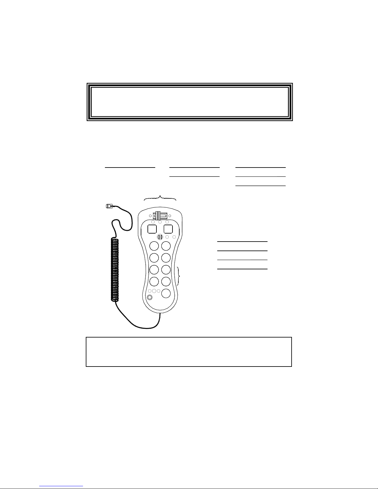
Installation Information
MODEL: LCS______________________
PURCHASE DATE: _______________
DEALER: __________________________
INSTALLER: _______________________
INSTALLATION DATE: ____________
AMPLIFIER SERIAL #: _______________
CONTROL HEAD SERIAL #:________________
ARROWSTICK BOX SERIAL #:______________
SIREN OPTION DIP SWITCHES
_____ Negative Auxiliary Switching
_____ Negative Park Kill Switching
_____ Two-Tone Enabled
_____ Phaser Disabled
_____ Slide Switch Pursuit Disable
CONTROL HEAD OPTION JUMPERS
_____ Audible Beep disable
_____ S4 Activates S1+S2+S3
_____ Momentary S3
_____ 8 sec. gun lock (S4)
_____ Auxiliary = Manual
_____ Wail Tone Auto-Activate
_____ TD WARN Auto-Activate (LCS881 only)
ARROW STICK OPTION JUMPERS
(LCS881 ONLY)
_____ Phantom Mode
_____ Fast rate arrow
_____ Low power (Dim)
_____ 6 head arrow (1 & 8 flash)
_____ 8 head arrow
_____ Group 2 Traveling arrow
_____ Double blink end arrow
Please Note: These instructions are provided as a general guideline only. Some
vehicles may require special mounting, wiring, and/or weather-sealing. This is the
sole responsibility of the installer. Star Headlight & Lantern Co., Inc. assumes no
responsibility for the integrity of the installation for this or any of its products.
-i-
Page 3
(Installation Information CONT’D)
IMPORTANT: Please read all of the following instructions before installing
your new light. Failure to follow these safety precautions
may result in damage to your light or vehicle and may result
in serious injury or death to you and your passengers.
Use this chart to label the function of your switches.
SLIDE SWITCH FUNCTIONS
POSITION 1 POSITION 3
L1 L1
SLIDE SWITCH
OFF L1 L2 L3
S1 S2
S4S3
POSITION 2
SAME AS IN POSITION 1 SAME AS IN POSITION 1 & 2
L1
L2
L2
L3
PUSH BUTTON SWITCH FUNCTIONS
S1
S2
S3
PUSH
BUTTON
SWITCHES
S4
SAME AS IN POSITION 2
Important
: This product is used to warn traffic. Improper use may result in vehicular
collision, personal injury and/or death. Star Headlight & Lantern Co., Inc., and its
subsidiaries shall not be held responsible for damages directly or indirectly caused by
improper use of this product.
Due to continuous product improvements, we must reserve the right to change any specifications and
information, contained in this manual at any time without notice. Star Headlight & Lantern Co., Inc. makes no
warranty of any kind with regard to this manual, including, but not limited to, the implied warranties of
merchantability and fitness for a particular purpose. Star Headlight & Lantern Co., Inc. shall not be liable for
errors contained herein or for incidental or consequential damages in connection with the furnishing,
performance, or use of this manual.
NOTICE
-ii-
Page 4

Table of Contents
INSTALLER INFORMATION i-ii
GENERAL DESCRIPTION 1
INSTALLATION NOTES 2
INSTALLER SELECTABLE OPTIONS 2-8
Siren Option DIP Switches 3-5
Control Head Option Jumpers 6-8
MOUNTING 9-10
Siren Amp & Relay Control Box 9
Cradle Mounting 9
Arrow Stick Control Box 10
ELECTRICAL CONNECTIONS 11-17
Wire Size And Termination 11
Siren Amplifier 11-14
Siren Wiring Diagram 13
Horn Ring Transfer Wiring Diagram 14
RFI Reduction and RFI Choke Installation 15
Input Power and Switch Output Connections 16-17
Light Wiring Diagram 17
ARROW STICK SETTINGS AND CONNECTIONS 18-22
Arrow Stick Option Jumpers 18-19
Arrow Stick Wiring 20-22
LABEL INSERTION 22
OPERATION 23-26
General 23
Slide Switch 23
Push Button Switches 23
Siren Mode Buttons 24
Microphone 25
PA Volume 25
Arrow Stick Controls 25
Speaker Diagnostics 25
Radio Repeat Volume 26
Auxiliary Input 26
Park Kill 26
Fuses 26
SERVICE 27-30
Troubleshooting 27
Parts 28
Specifications 28
Warranty 29
Returned Materials Authorization (RMA) Form 30
FLANGED CONTROL HEAD TEMPLATE 31
-iii-
Page 5

General Description
The LCS880 series is a premium remote system that combines the siren amplifier, the
siren controls, and light controls all in one system. A single slim-line hand-held remote
control head combines the noise-canceling microphone with a built in siren, as well
as many of the switch and light controls for the vehicle. The control head contains
illuminated buttons that change color to indicate status. The face of the hand-held
controller is sealed around every push button to help prevent liquid from entering
the electronics. The amplifier is a 200W siren amplifier unit designed for single or dual
100W speaker use. The LCS881 model adds an additional button for full arrow stick
control.
The hand-held controller contains several distinct controls for operation of vehicle
devices. The slide switch allows quick pursuit mode operation. The far right slide
position can be set up to activate maximum lights and siren for pursuit mode. There
are six push buttons to operate the siren and four push buttons to control four
different lighting or auxiliary functions. The LCS881 also adds an additional button for
control of an arrow stick.
The LCS880 series is designed to allow maximum versatility in mounting. The handheld controller is remote from the siren amplifier and light relay control box, creating
a compact user interface that can be mounted onto the dashboard, overhead, or
in the center console. The hand-held controller comes with a cradle for mounting.
The amplifier box and arrow stick control box can then be mounted remotely in the
trunk, under the dashboard, under the seat, or wherever convenient.
Siren operating modes include Wail, Yelp, Phaser, and Radio. A Noise Canceling PA
Override is available in all modes. A Manual button allows tone toggle operation
and manual siren control. The Air Horn button will override any siren tone. The
vehicle horn switch may also perform the Manual push button function via an
auxiliary input. Ten option jumpers allow the unit to be fully customized to the
operators' needs. Options include: Phaser vs. Two-Tone, Phaser disable, 8 second
timed gunlock release, and momentary vs. lock-on/lock-off switch operation. A Park
Kill option is provided for connection to a door switch, etc. to disable the siren when
exiting the vehicle. Both a PA volume and a Radio volume are provided.
The LCS880 series has been designed with several protection features to provide
exceptional field service. Excessive high or low voltage detection will disable the
siren output, protecting both the amplifier and the speaker. Fused inputs provide
safety against reverse polarity. Speaker diagnostics provides user feedback as well
as shutdown protection against speaker opens and shorts. The first four light output
functions are individually protected with 20A fuses, while the Horn Ring Transfer (HRT)
output function is protected with a 2A in-line fuse. CAUTION: These protection
features will not guard against overloading the outputs.
The LCS880 series is available in the following different versions:
LCS880-008 Standard version with slide switch, full siren controls, and light
LCS881-008 Enhanced version with all the standard controls plus arrow stick
controls. Includes a remote hand-held controller with microphone
and a siren amplifier/switch relay box.
controls. Also includes the arrow stick control box.
-1-
Page 6

Installation Notes
Proper installation of the unit is essential for years of safe, reliable operation. Please
read all instructions before installing the unit. Failure to follow these instructions can
cause serious damage to the unit or vehicle and may void warranties.
Qualifications - The installer must have a firm knowledge of basic electricity, vehicle
Keep These Instructions - Keep these instructions in a safe place for future reference.
Contents should include:
electrical systems, and emergency equipment.
Advise the vehicle operator of the location.
1 - Hand Held Controller
1 - Amplifier and Light Control Box
1 - Amplifier Wire Harness with Connector
1 - 25’ Amplifier Communication Cable (6-wire telephone style cable)
1 - Extended Cable Adapter
1 - Mounting Hardware
1 - Label Set
1 – RFI Filter
1 - Installation and Operating Instructions
1 – TDC850 Arrow Stick Control Box (LCS881 models only)
1 - Arrow Stick Communication Cable (telephone style cable) (LCS881 models only)
1 - Communication Cable Splitter (LCS881 models only)
1 – 12” Communication Cable (LCS881 models only)
Installer Selectable Options
The LCS880 and LCS881 have several options that can be selected during
installation. Jumpers and DIP switches on the printed circuit board inside the
amplifier case, inside the control head, and inside the arrow stick control box
(LCS881 only) allow the installer to select these various options. These options should
be set before installation of the unit.
Siren Option DIP Switches (located in the amplifier case):
Control Head Option Jumpers (located inside the control head)
• Auxiliary input polarity
• Park Kill input polarity
• Two-tone replacement of Phaser tone
• Phaser Disable
• Slide Switch Pursuit Disable
• Audible beep disable
• Button S4=S3+S2+S1
• S3 = Momentary switch
• 8 second timed gun lock release (S4)
• Auxiliary control (Manual vs. Horn)
• WAIL Tone Auto Activate on Position L3 of Slide Switch
• Arrow Stick WARN Auto Activate on Position L3 of Slide Switch
-2-
Page 7
(Installer Selectable Options CONT’D)
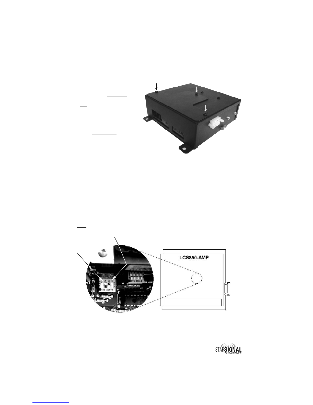
SIREN OPTION DIP SWITCHES
Amplifier Cover Removal
Loosen the three protruding
Philips head screws located on
the top of the amplifier unit. Slide
the cover off.
CAUTION:
DO NOT OVER
TIGHTEN SCREWS!
Auxiliary Input Polarity
Applying a positive voltage to the green wire normally activates the auxiliary
function (Air Horn standard/MANUAL function optional).
The wiring diagram on page 13 shows both connection examples.
To instead have the AUX function activate when the green wire is connected to
ground (negative) .
1. Turn “AUX POS” DIP switch off.
2. Turn “AUX NEG” DIP switch on.
Diagram showing NEG AUX set up
-3-
Page 8
(Installer Selectable Options CONT’D)
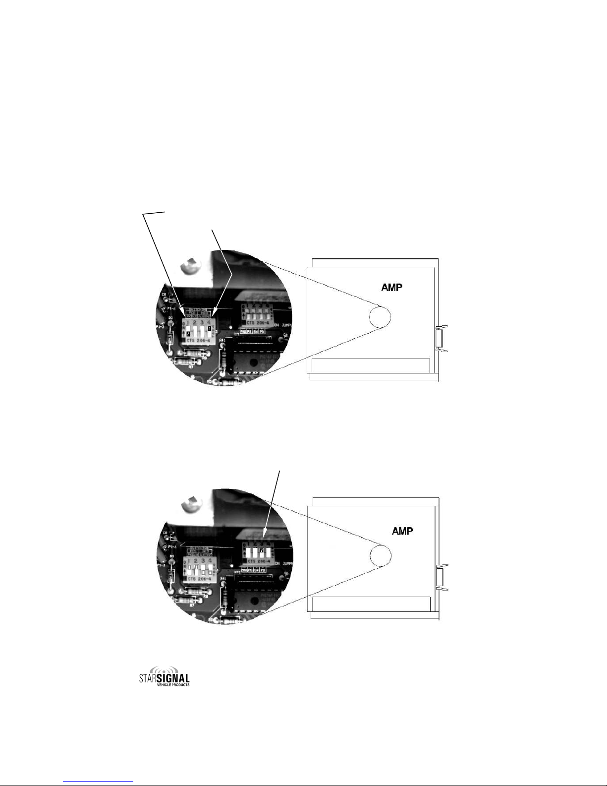
Park Kill Input Polarity
The Park Kill (Cutout) Input turns off any siren tone output when activated, and
remains off until a control is activated or changed. The wiring diagram on page 13
shows two connection examples.
Connecting the white wire to positive (+12 VDC) normally activates the Park Kill
input. To instead have it activate when the white wire is connected to ground
(negative):
1. Turn “PK POS” DIP switch off.
2. Turn “PK NEG” DIP switch on.
Two-Tone
If desired, the Phaser sound can be replaced with a Two-Tone sound. This can be
done by turning on (up position) DIP switch #3 in the amplifier (labeled SW).
-4-
Page 9
(Installer Selectable Options CONT’D)
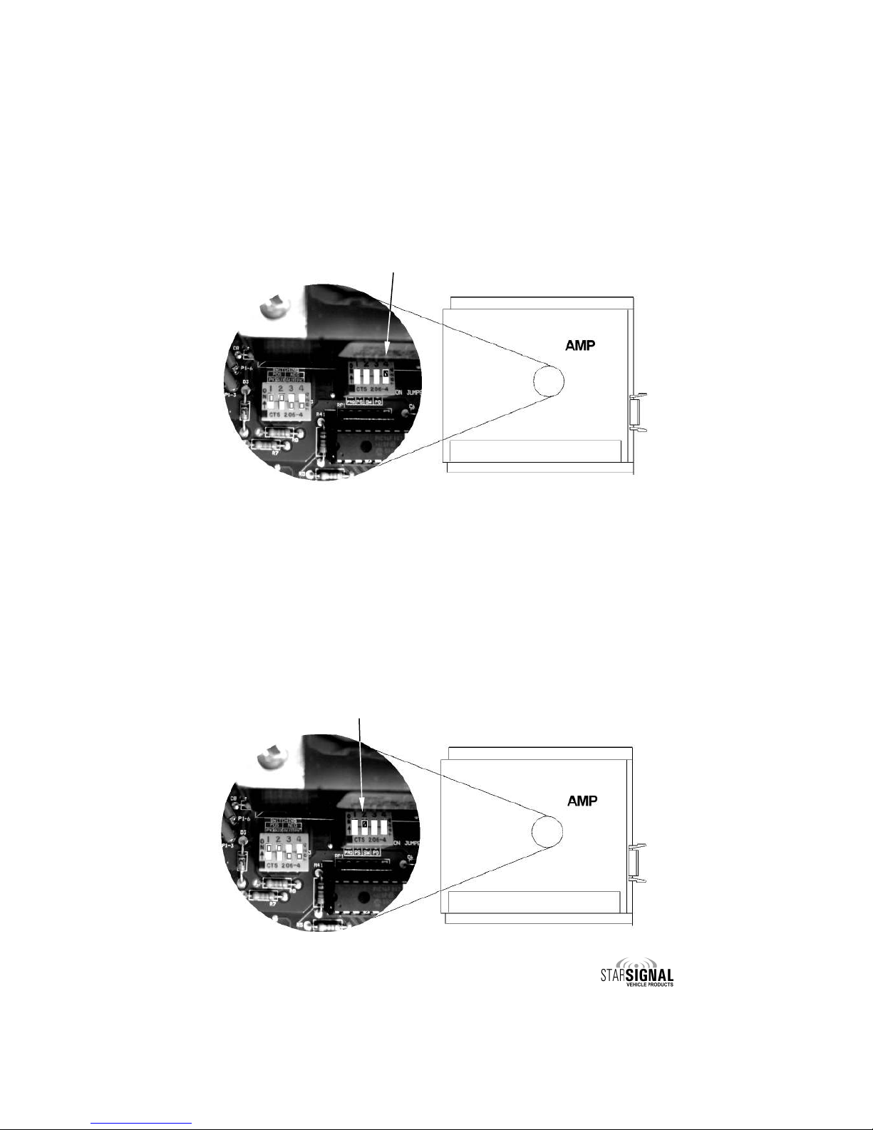
Phaser Disable
The Phaser function can be completely disabled by turning on (up position) DIP
switch #4 in the amplifier (labeled PD). This will also disable the MAN button while
the siren is in Phaser mode (which normally would produce a Two-Tone sound).
Pursuit Disable
Slide switch position 3 normally activates:
• All three light functions (L1, L2, & L3)
• The siren (into the Wail mode)
• Warn pattern on the Arrow Stick (LCS881 series only)
To disable the automatic activation of the siren and Arrow Stick, move DIP switch #2
in the amplifier (labeled PS) to the “UP” position.
-5-
Page 10

(Installer Selectable Options CONT’D)
CONTROL HEAD OPTION JUMPERS
Five jumpers located inside the hand held controller can be used to select various
options. Review the chart below to determine if you want to change any of the
default settings.
Jumper Controlled Options
Jumper
Audible Beep
Disable
S4=S3+S2+S1
(LCS880 ONLY)
Momentary (S3)
S4 Timer
Auxiliary Control
(Horn vs. Manual)
Standard Setting
(jumper on both pins)
An audible beep is heard when
the buttons in the control head
are pressed.
S4 is an independent switch
controlling output S4.
Push button S3 is a standard
ON/OFF button.
Push button S4 is a standard
ON/OFF button.
The green auxiliary (AUX) wire in
the siren amplifier harness is
connected to the vehicle horn
ring, and activates the siren’s AIR
HORN for all siren modes except
RADIO.
Optional Setting
(jumper only on one pin)
No beep when the buttons in the
control head are pressed.
When pressed, S4 automatically
activates S3, S2, and S1 buttons.
S3 becomes a momentary switch,
thus only being active while being
held in.
S4 used for Gun Lock - Stays
activated for only 8 seconds when
pressed.
AUX wire duplicates the function of
the MAN push button instead of the
HORN.
Programmable Options (LCS881 ONLY)
Jumper
WAIL Tone
Auto-Activation With
Standard Setting
WAIL tone auto-activated in slide
switch position 3 (L3)
Slide Switch
Traffic Director
WARN Pattern
Auto-Activation With
The WARN pattern on your Traffic
Director will auto-activate in slide
switch position 3 (L3)
Slide Switch
S4=S3+S2+S1
(LCS881 ONLY)
S4 is an independent switch
controlling output S4.
-6-
Optional Settings
(Programmed with PROGRAM
jumper removed)
WAIL tone auto-activated in L1 or L2,
WAIL tone NOT activated in L3
TD WARN pattern auto-activated in
L1 or L2.
TD WARN pattern NOT activated in
L3
When pressed, S4 automatically
activates S3, S2, and S1 buttons.
Page 11
(Installer Selectable Options CONT’D)
If you are NOT changing any of the options described on the
previous page, skip this section.
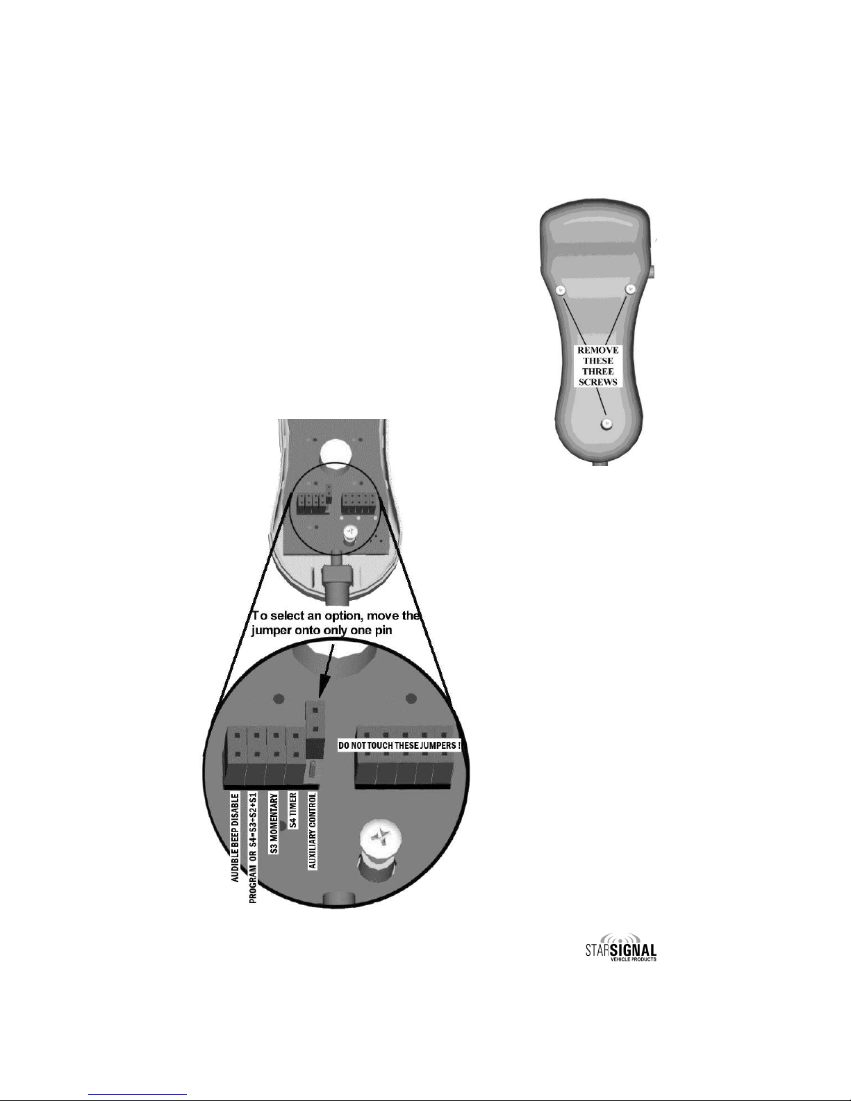
Control Head Cover Removal
• Remove the three Philip head screws recessed in the
back of the hand held controller.
• CAREFULLY remove rear cover using caution so as not to
lift circuit board and membrane switch away from front
faceplate.
• Locate the 10 jumpers located near the microphone coil
cord strain relief.
• DO NOT REMOVE ANY OF THE FIVE JUMPERS ON THE RIGHT
SIDE !!!
• By default, the five jumpers on the left side come installed
across both pins.
Jumper Controlled Options
To change any of these options, move
the corresponding jumper from both
pins to only the top pin as shown in the
diagram to the left.
•
Audible Beep Disable
•
S4=S3+S2+S1 (LCS880 only)
•
S3 Momentary
•
S4 Timer
•
Auxiliary Control
-7-
Page 12

(Installer Selectable Options CONT’D)
Programmable Options (LCS881 ONLY)
•
S4=S3+S2+S1
•
WAIL Tone Auto-Activate By Slide Switch
•
TD WARN Auto-Activate By Slide Switch
The LCS881 has a number of additional programmable option that are NOT
available in the LCS880. To program these options:
• Power up the unit and remove the PROGRAM jumper.
• With the slide switch in the OFF position, toggle PB4.
Green: S4= Standard On Off Switch
Red : S4=S3+S2+S1
• Move the slide switch to positions L1, L2, and L3.
• Toggle the WAIL button to program whether or not you want the WAIL tone to
auto-activate whenever the slide switch is in each of those positions during
normal operation.
• Toggle the LRCO button to program whether or not you want the Traffic
Director to auto-activate into a WARN pattern whenever the slide switch is in
each of those positions during normal operation.
Green: Disabled
Red : Enabled
-8-
Page 13

Mounting
SAFETY PRECAUTIONS
For the safety of the installer, vehicle operator, passengers, and the community
please observe the following safety precautions. Failure to follow all safety
precautions and instructions may result in property damage, injury or death.
DO NOT mount in air bag deployment area.
Devices should be mounted only in locations listed in SAE standard J1849.
Controls should be placed within convenient reach of the driver.
Assure clearances before drilling in vehicle.
Sound levels produced by attached speakers can cause permanent hearing loss.
Never operate this unit without adequate hearing protection for you and others in
the area.
SIREN AMPLIFIER & RELAY CONTROL BOX
• The amplifier should be mounted in a location such as the driver compartment
firewall, under the seat, or in the trunk.
• Do not mount the amplifier in the engine compartment or in an area that would
be allowed direct exposure to weather elements.
• Choose a mounting location away from any air
bag deployment areas.
• Assure adequate ventilation to prevent
overheating.
Mount the amplifier unit through the
four 1/4” holes located in the flanges
(two visible and two not shown in the
picture to the right).
(OSHA 1910.95)
CRADLE MOUNTING
•
The LCS880 and LCS881 both include a cradle for
storing the hand-held controller when it is not in use.
•
Select a location so that the cable does not interfere
with the vision of the driver or the operation of any
controls, including, but not limited to, the steering
wheel, gear shifter, and/or airbag.
•
The cradle comes with four mounting holes predrilled
in it. Only two screws are normally necessary to
secure the cradle to the dash. Once you have
selected a location, use the cradle as a template
and mark the two mounting holes you will be using.
•
Carefully drill two 1/16" pilot holes for your screws. Be
sure to check for wiring and/or any other obstructions
behind the mounting hole locations.
•
Once the holes are drilled, use the two self-tapping
Phillip head screws to secure your cradle.
-9-
Page 14

(Mounting CONT’D)
ARROW STICK CONTROL BOX MOUNTING
(MODEL LCS881 only)
• Review the Arrow Stick Settings and Connections (pages 18-22) section for
details on any option jumper settings prior to installing this control box.
• The TDC850 arrow stick control box is usually mounted near the siren amplifier
and relay control box in a location such as the driver compartment firewall,
under the seat, or in the trunk.
• Do not mount the amplifier in the engine compartment or in an area that would
be allowed direct exposure to weather elements.
• Choose a mounting location away from any air bag deployment areas.
• Assure adequate ventilation to prevent overheating.
• The arrow stick controller comes with a 7-foot communication cable that must
be plugged into the siren amplifier.
• A “U” bracket is provided for mounting. The “U” bracket may be used as a
template when locating and drilling mounting holes.
-10-
Page 15

Electrical Connections
WIRE SIZE AND TERMINATION
• The wiring diagrams on pages 13 and 17 show the minimum wire size used for
each connection, along with recommended lead color.
• If the wire is longer than 10 ft., use the next larger wire size.
• Use only high quality crimp connectors.
• Make sure all connections are tight.
• Route wiring to prevent wear, overheating and interference with air bag
deployment.
• Use grommets and sealant when passing through compartment walls.
• Minimize the number of splices to reduce voltage drop.
• Ground connections should be made directly to the negative of the vehicle
battery. If not possible, connect only to substantial chassis components.
• Install and check all wiring before connection to vehicle battery. SEE TABLE
BELOW FOR CORRECT WIRE SIZING!
• All conductors should be constructed of stranded copper with thermoplastic
insulation.
CAUTION: All wires should be rated for at least 125% of their maximum current load.
All wires connected to the positive terminal of the battery should be fused at the
battery for their rated load. The load can be calculated by adding all lamp
wattages and dividing by 13. Load (Amps) = Total Watts / 13 volts. Do not use 1/4"
diameter glass fuses, as they are not suitable for continuous duty above 20 amps.
RECOMMENDED WIRE SIZE, AMP CAPACITY & CONSTRUCTION
Ampacity Range SAE Wire Size Gauge/No. of Strands
5A - 10A #16 29/19
10A - 15A #14 27/19
15A - 30A #12 25/19
30A - 40A #10 23/19
40A - 50A #8 21/19
SIREN AMPLIFIER
Communication between the control
head and the amplifier is made via a
communications cable using an RJ11
jack located on the opposite side of
the power connector. CAUTION:
Please note that the cable used IS NOT
a standard telephone cord and
CANNOT be replaced with one.
Make all electrical connections to the power connector before installing the
connector on the unit.
If the unit needs service, both the communication cable and the power connector
can be easily removed without unwiring the connector.
-11-
Page 16

(Electrical Connections: Siren Amplifier CONT’D)
Siren electrical power connections to
the amplifier are made using a
removable connector located on the
back of the amplifier case.
The power supply to the siren unit must
be capable of delivering peak currents up to
50 amps for adequate short circuit protection
and reliable operation. The preferred source
is directly at the vehicle battery. The unit is
internally fused. The wiring diagram on the next page shows detail of how to wire
the connector on the amplifier to the vehicle.
Make all electrical connections to the power connector before installing the
connector on the unit.
Mandatory Siren Wiring Connections:
BLACK LEADS:
RED LEADS:
BROWN LEADS:
PINK LEAD:
Optional Siren Wiring Connections:
BLUE LEADS:
GREEN LEAD:
Optionally this may be used to mimic the Manual button function when
WHITE LEAD:
NOTE: If not used, cut lead short and insulate with electrical tape.
ORANGE LEAD:
(GROUND) - Connect BOTH black wires to the nega tive of the battery, or
to a good chassis ground. Be sure to use minimum size #14 AWG wire.
(POWER/+12VDC) - Connect BOTH red wires to the positive of the
battery, or to a high current power buss. Be sure to use minimum size
#14 AWG wire.
(SPEAKER) - Connect one lead to each terminal or lead of the speaker.
If connecting a second speaker in parallel, you must observe the polarity
of the speakers (phasing). Be sure that the positive terminals of both
speakers are connected together to the same brown wire from the siren.
(IGNITION SWITCHED POWER) - Connect the pink wire to your ignition-
controlled power (or other switched power source). This will turn the
power to your unit on and off.
(RADIO REPEAT) - Connect one blue lead to each terminal of the two-
way radio speaker or output connector of the radio. Use #18 AWG wire.
(AUX) - Use if you would like to activate the siren’s AIR HORN when the
vehicle horn is pressed. Connect to horn ring circuit or other remote
switch. Circuit may be positive or negative with proper jumper selection.
See Auxiliary Input Polarity section on page 3 for jumper details. NOTE:
Cut lead short if not used & insulate with electrical tape.
the vehicle’s horn is pressed. See Auxiliary Control on pages 6-7 for
Control Head jumper setting.
(PARK-KILL) - Connect to dome light or added door switch. Circuit may
be positive or negative with proper jumper selection. See Park Kill Input
Polarity section (page 4) for jumper details.
(HORN RING TRANSFER or LOW CURRENT OUTPUT) - You only need to
connect this wire if you will also be connecting the green AUX wire to
your horn ring circuit, thus enabling the driver to control the siren
functions by using the vehicle horn. This output is enabled whenever
the handset is activated with the recessed On/Off switch on the side
and it temporarily deactivates the vehicle’s horn. This allows the use
of the horn ring switch without actually sounding the vehicle’s horn.
Connect the Orange wire to the Horn Ring Transfer Relay as shown the
HRT Wiring Diagram on page 14.
NOTE: If not used, cut lead short and insulate with electrical tape.
-12-
Page 17

(Electrical Connections: Siren Amplifier CONT’D)
+12 VDC
Light
Dome
Switch
To High Current Device
11 OHMS
(OPTIONAL)
SPEAKER 2
Added Door
+
Siren Wiring Diagram
Switch is Turned On)
Device (Activated When
Hand-Held Controller Power
Optional Relay For Horn Ring
Transfer or Other High Current
Horn
HORN
VEHICLE
Horn Jumper Selected
Negative Switching AUX
+12 VDC
Positive Switching AUX
OR
HORN
VEHICLE
Horn Jumper Selected
Switch/Relay
AUX
Switching
Negative
AUX
Positive
11 OHMS
SPEAKER 1
2 Amp fuse
Switching
OR
9 - Green (#18 AWG)
8 - White (#18 AWG)
12 - Brown (#14 AWG)
11 - Pink (#18 AWG)
10 - Orange (#18 AWG)
Door Switch
+12 VDC
+
Jumper Selected
Positive Switching PK
OR
Jumper Selected
Negative Switching PK
RADIO
+
to the output jack of radio
Connect the Blue wires to
the terminals of speaker or
+
BATTERY
2 - Black (#14 AWG)
4 - Red (#14 AWG)
7 - Brown (#14 AWG)
6 - Blue (#18 AWG)
5 - Black (#14 AWG)
3 - Blue (#18 AWG)
1 - Red (#14 AWG)
+12 VDC
Horn
Switch/Relay
+12 VDC
power or other
Ignition controlled
SIREN
AMPLIFIER
switched power source
-13-
Page 18

(Electrical Connections: Siren Amplifier CONT’D)
Wiring Diagram for OPTIONAL
Horn Ring Transfer (HRT)
Use this wiring diagram if you are connecting the Orange wire to utilize the Horn Ring
Transfer Feature. This feature de-activates the vehicle horn when the handset is
activated with the recessed On/Off switch on the side. The diagram below shows wiring
for both positive and ground-side switched horns, using an installer-supplied relay.
+12 VDC
Cut your horn wire
here and insert the
installer supplied relay
Ground Side
Horn Switch
Green Wire From Amp
Orange Wire From Amp
Connect like
this for
Ground Side
Horn Switch
OR
Connect like
this for
Positive Side
Horn Switch
Orange Wire From Amp
Green Wire From Amp
2 Amp fuse
+12 VDC
Negative Switching
AUX Jumper Selected
Positive Switching
AUX Jumper Selected
2 Amp fuse
Positive Side
Horn Switch
User Supplied Optional SPDT Relays
(Opened When Recessed On/Off
Switch On Handset is Activated)
VEHICLE
HORN
Cut your horn wire
here and insert the
installer supplied relay
-14-
VEHICLE
HORN
Page 19

(Electrical Connections CONT’D)
RFI REDUCTION AND RFI CHOKE INSTALLATION
The following steps are recommended when installing, to help reduce RFI:
1. Make sure that both the control head and amp are securely attached to good
chassis ground (i.e. no paint in-between the chassis and the grounding
terminal).
2. Keep the siren control head and amplifier as far away from the police radio as
is practical.
3. Check that the police radio antenna wire makes a right angle from the back of
the police radio and runs on one side of the vehicle. The communications
cable for the siren should make a right angle out of the back of the control
head and exit in the opposite direction from both the police radio antenna wire
and the police radio power wires.
4. Excess communication cable from the control head to the amp should be
tightly bound back near the amplifier box.
5. One of the RFI chokes (STAR P/N: P30039-57) should be placed around the
communications cable at the back of the siren amplifier box.
6. The second RFI choke should be placed around the Red and Black wires exiting
the siren amplifier box.
RFI
CHOKES
ANTENNA LEAD
2-WAY
RADIO
AMP
Minimum 3'
SIREN
AMP
SIREN CONTROL
HEAD
SIREN COMMUNICATIONS CABLE
SIREN POWER AND GROUND WIRES
RADIO POWER WIRES
BATTERY
RADIO
-15-
Page 20

(Electrical Connections CONT’D)
INPUT POWER AND SWITCH OUTPUT CONNECTIONS
Top View
(Cover Removed)
Input Power
Slide Switch
Outputs
Push Button
Outputs
Side View
(REFER TO LIGHT WIRE DIAGRAM ON NEXT PAGE, AS WELL AS TO WIRE SIZE TABLE ON
PAGE 11 FOR PROPER WIRE SIZES!)
The electrical connections for input power, slide switch outputs, and the push button
outputs are made to the control box (amplifier) using terminal blocks (top diagram
above).
Input Power: (Left Terminal Block) Connect +12VDC to the 3 large barrier
style terminals. When controlling lights with a large amount
of current (>15A) power should be supplied to all three
inputs.
Slide Switch Outputs: (Center Terminal Block) Connect the lights that you wish to
activate in the corresponding slide switch positions to the
L1, L2, and L3 outputs (20A max each). (Note: the second
slide switch position activates both L1 and L2 and the third
slide switch position activates L1, L2, and L3).
Push Button Outputs: (Right Terminal Block) Connect the lights that you wish to
activate with corresponding pushbutton switches S1-S4 to
the S1-S4 outputs (20A max each).
-16-
Page 21

(Electrical Connections: Light Relay Control Box CONT’D)
Light Wiring Diagram
Power to device activated by push button switch S4
Power to device activated by push button switch S3
Power to device activated by push button switch S2
S4 - (#12-16 AWG)
S3 - (#12-16 AWG)
S2 - (#12-16 AWG)
20A
20A
20A
Power to device activated in slide switch position 3
Power to device activated by push button switch S1
S1 - (#12-16 AWG)
20A
Power to device activated in slide switch positions 2 and 3
Power to device activated in slide switch positions 1, 2, and 3
+
BATTERY
2 - Red (#8-12 AWG)
3 - Red (#8-12 AWG)
L3 - (#12-16 AWG)
L2 - (#12-16 AWG)
L1 - (#12-16 AWG)
20A
20A
20A
LCS800
AMPLIFIER
1 - Red (#8-12 AWG)
SEE PAGE 11 FOR
CORRECT WIRE SIZING!!!
-17-
Page 22

Arrow Stick Settings and Connections
(LCS881 only)
The TDC850 controller that is shipped with the LCS881 has been designed so that it
can operate three different styles of traffic directors:
• Independently Switched Heads: Each Head is independently controlled by a
ground-side switched wire.
• 3-Wire Logic Controlled Heads: Left, Right, and Warn functions are controlled
by delivering power to 3 separate wires.
Center-Out function activated by delivering
power to both Left and Right functions
(wires) at the same time.
• 4-Wire Logic Controlled Heads: Specifically designed for the DL15-30W.
Power wire activates Warn function. Right,
Left, and Center-Out functions controlled by
delivering low current to 3 separate wires (in
addition to Power wire).
Please review the instructions that came with your traffic director and then
reference the corresponding section(s) in this manual for the type of traffic director
that you will be installing.
ARROW STICK OPTION JUMPERS
Included with the LCS881 is the TDC850 arrow stick controller. There are several
jumpers located inside the TDC850 that control different options for traffic directors.
Review the following section to determine if you need to open the case and
change any of the jumper options inside the TDC850.
Arrow stick Control Box Cover Removal
1. Remove the four recessed Philip head screws (two
on each side of the arrow stick control box).
2. Remove the top cover by sliding it towards the
front of the unit.
Arrow Stick Control Mode Setting
The Standard Mode is designed to control traffic directors with independently
switched heads. If you have a 3- or 4-wire controlled arrow stick (as described
above), check the Option Header Location and configure the jumpers as pictured
below.
Extra Jumper
Locations
TDC850 Controller
Option Header
Location
Standard
Mode
3-Wire
Logic Mode
4-Wire
Logic Mode
-18-
Page 23

(Arrow Stick Settings and Connections CONT’D)
Jumper Options for Independently Controlled Heads
If you are installing a 3- or 4–wire logic
controlled arrow stick, skip this section. The
options described below only apply to arrow
sticks with independently controlled heads.
Jumper Defaulted In Center Header
Phantom:
Extra Jum per
Locations
Phantom M ode
The TDC850 is shipped with the jumper in
the Standard Operation position. In this
mode, the end lights follow the normal
“traffic directing” pattern you select.
Optionally you can select Phantom
Mode:
• In the “Phantom” mode, the end lights are
NOT part of the “traffic directing” patterns.
• Both end lights will flash back and forth in a
high speed “warn” type display any time the
slide switch is in position 1 or 2.
• ALL lights will automatically flash in a “random
flicker” pattern with the slide switch in position
3 (see SLIDE SWITCH on page 23).
To set your control box for Phantom mode, move the 1st jumper in the Option
Header Location back to the pins labeled PHANTOM in the Extra Jumper
Locations.
Jumpers Defaulted In Extra Jumper Location
To change one of these options, move one of the jumpers from the Extra Jumper
Locations over to the corresponding Option Header Location.
Fast Rate Arrow:
This setting increases the flash rate of the arrow stick for high speed or high traffic areas where
viewing time of the arrow is limited. In addition, selecting this option will also change the
“Warn” pattern from an alternating pattern to a random pattern.
Low Power:
If the arrow stick is to be used for nighttime operation, or you wish to reduce the power
consumption of the arrow stick, the output can be reduced by 50%.
Six Head Arrow †:
Use this option if your arrow stick contains only six heads. In this mode, under all patterns the
1st & 8th heads will alternate back & forth, operating as rear flashers.
Eight Head Arrow †:
Many arrow sticks contain directional arrows on either end (the 1st and 8th heads). The factory
preset arrow pattern will skip the first head in the right and left patterns so as to not confuse
the driver with the incorrect arrow direction. If your arrow stick does not contain directional
arrows on the ends and you wish to use all eight heads in your right and left patterns then set
this option jumper.
Group 2 Traveling Arrow (energy saving arrow) †:
Optionally selected where energy saving is desired. In this case only two heads will remain lit
during the arrow pattern, traveling across the arrow stick.
Double blink last head of arrow (end blink) †:
The last head to flash in an arrow can be optionally selected to blink twice at the end of the
arrow sequence.
† - These options are disabled when the controller is in PHANTOM mode.
TDC850 Co ntroller
All Other
Options
Standard Op eration
Fast Rate Arrow
Low Powe r Mode
6-Head Arro w w/Flashin g Ends
8-Head w/E nd Arrow
Group 2 T ravelling Arro w
Double Blin k Last Ligh t (End Blink)
Option Head er
Location
-19-
Page 24

(Arrow Stick Settings and Connections CONT’D)
ARROW STICK WIRING
The arrow stick control box comes
with a removable green terminal
block connector (Power
Connector). Remove the terminal
block from control box and loosen
all applicable terminal screws. This
will open the wire entries. Make the
power wire connections
as described in the section that corresponds to the type of arrow stick you are
connecting. Be sure to tighten down each screw once the appropriate wire is
inserted. After all power connections are complete, insert the terminal block into the
mating receptacle in the back of the control box. Tighten the two terminal block
locking screws on either end of the block to prevent it from vibrating loose.
Verify that your corresponding jumper setting shown on page 18 is correct for the
type of arrowstick you are connecting and use the appropriate wiring diagram
below or on the following page. All installations will require the Ground and Power
connections described below.
Ground: Connect to good chassis ground, or the negative of the vehicle
battery.
Battery +12 VDC: Connect this terminal to the same fused, +12 VDC source that
the pink wire from the amp is connected to (see pages 12-13).
NOTE: This terminal must be connected to the same +12VDC
source as the pink wire in order to prevent inadvertent
momentary activation of one or more of the lights in your
traffic director. For non-LED arrow sticks, use 12 AWG wire for
all power and ground connections.
Arrowsticks With Independently Switched Heads
VERIFY MODE JUMPER
SETTING ON PAGE 18 !!
This diagram describes how to
connect a standard traffic
director that utilizes eight (8)
ground side switched wires (one
for each head).
1 2 3 4 5 6 7
BROWN
RED
ORANGE
YELLOW
SWITCHED GROUND F OR EACH LIG HT
(6 head arrow sticks use 2-7 only)
-20-
108 9 11 12
BLUE
GREEN
GRAY
CABLE SHIELD GROUND (BARE WIRE)
VIOLET
BATTERY +12VDC
LARGE RED - POWER TO ARROW STICK
GROUND (BATTERY -)
Page 25

(Arrow Stick Wiring CONT’D)
Arrowsticks With 3-Wire Logic Control
VERIFY MODE JUMPER
SETTING ON PAGE 18 !!
1 2 3 4 5 6 7 8 9 10 11 12
EMPTY
EMPTY
This diagram shows how to connect the
wires from an arrow stick that is logic
controlled by 3 positive switched wires
(Right, Left, and WARN) AND uses a
separate POWER wire.
Note: Terminals 4, 5, and 8 will only deliver
a maximum output of 4mA. They are
designed to be used as “signal” wires.
You cannot use this controller if your arrow
stick uses the function wires to deliver
power for those functions.
Arrowsticks With 4-Wire Logic Control
EMPTY
ARROW STICK LEFT WIRE
ARROW STICK RIGHT WIRE
BOTH FOR
CENTER-OUT
POWER TO ARROW STICK
BATTERY +12VDC
EMPTY
EMPTY
ARROW STICK WARN
GROUND (BATTERY -)
ARROW STICK GROUND WIRE
VERIFY MODE JUMPER
SETTING ON PAGE 18 !!
The diagram to the right shows
how to connect the wires from a
DL15-30W (or similarly controlled)
arrow stick to the TDC850.
The colors shown represent those
used in the DL15-30W harness.
Wire colors may vary for other
arrow sticks.
1 2
EMPTY
BLACK - ARROW STICK GROUND WIRE
-21-
3
5 6
4
GREEN - ARROW STICK RIGHT WIRE
EMPTY
YELLOW - ARROW STICK LEFT WIRE
8 9 10
7
EMPTY
EMPTY
VIOLET - ARROW STICK CENTER-OUT WIRE
11 12
RED - ARROW STICK POWER/WARN
BATTERY +12VDC
EMPTY
GROUND (BATTERY -)
Page 26

(Arrow Stick Settings and Connections CONT’D)
CAUTIO N: NOT REPLACE ABLE WITH A
STANDAR D TELEPHONE CABLE
!
6-wire
Cable
Splitter
TDC850 ARROW STICK POWER SUPPL Y
20 2
SIREN
AMPLIFIER
HAND-HELD
CONTROLLE R
A communications cable splitter is
provided with these units. Using the
communication cables, plug both the
Arrow stick box and the control head into
the cable splitter, and then plug the
splitter into the amplifier box.
CAUTION: Please note that these cables ARE NOT standard telephone cords and
CANNOT be replaced with one.
Testing - Test all siren functions after installation to assure proper operation.
Test vehicle operation to assure no damage to vehicle.
Label Insertion
Once the wire connections have been, labels
can be inserted into the switches. The product
is shipped with 30 different labels for these push
buttons. Select the desired label inserts
(provided). Insert the label into each button
and tuck it under the lip of the switch.
The siren labels come pre-installed and may be
used for reference when inserting light function
labels.
-22-
Page 27

Operation
GENERAL
This unit is designed for easy operation under
the stress associated with high-speed pursuit.
Many light and siren functions are accessible
with one simple motion of the slide switch.
POWER
The unit is turned On and Off by a recessed
switch on the side of the hand held
controller. All functions are disabled until
the unit is switched on.
SLIDE SWITCH
The slide switch is designed for quick pursuit
mode operation. The far left position (OFF) will
not activate any outputs.
Position 1: Activates the first set of lights
Position 2: Activates both the 1st and 2nd set
Position 1 & 2: (LCS881 only) If you have the 1st
Position 3: Generally used for the FULL PURSUIT MODE. It allows for quick
(connected to L1).
of lights (connected to L1 and L2).
jumper in the Arrow Stick Light
Controller set for Phantom Mode (see page19), the end lights in
your traffic director will flash in a
high speed “Warn” pattern in both
positions 1 and 2.
activation of both the lights and the siren in one motion. When the
slide switch is moved to Position 3, the following will activate:
• All three sets of lights (connected to L1, L2, and L3)
• The siren (WAIL mode)
• All of the Traffic Director lights will flash in a “WARN” pattern
(LCS881 only)
Note: The auto-activation of the siren and the arrow stick may be
disabled if desired. (Refer to the Pursuit Disable section on page 5).
PUSH BUTTON SWITCHES
S1, S2, S3, and S4 control the devices connected to the corresponding output
terminals described on pages 16-17. Press once to activate, then press again to
deactivate.
Optionally, S3 can be set to be a momentary switch, S4 can be set as a timed “Gun
Lock” button, or S4 can be set to activate S1, S2, and S3 concurrently (see Control
Head Option Jumpers on pages 6-8).
-23-
Page 28

(Operation CONT’D)
SIREN MODE BUTTONS:
The six push buttons towards the top of the
control head allow full siren operation.
When not activated, these buttons are
backlit in green for nighttime viewing.
When activated, an audible beep is heard,
and the backlighting turns red.
MAN (Manual)
This button is used to temporarily change the siren output. Review the chart below
for a description of the various outputs, depending upon which mode you are in.
MAN BUTTON FUNCTIONS
Siren Mode
Selected:
WAIL
YELP
PHSR
RADIO
NONE
Speaker
Output:
Wail Yelp
Yelp Phaser
Phaser Two-Tone
Radio Repeat No Effect
No Output Creates a manual WAIL tone while button is being held that
Pressing the MAN button Changes the Speaker Output to:
sweeps down when the button is released.
HORN (Air Horn)
This momentary push button switch provides a simulated air-horn tone while
pressed. This can be used to either replace, or to supplement the normal vehicle
horn and is useful at intersections or in high noise areas. This tone will override all
other siren tones.
WAIL
A normal rise-fall tone used on highways and areas with low traffic or constant traffic
flow.
YELP
A rapid warble tone used in light to moderately congested areas.
PHSR (Phaser)
Ultra-fast warble one used for maximum attention in highly congested areas.
RADIO
Also known as Radio Repeat, this function amplifies a two-way radio speaker input
for re-broadcast outside the vehicle through the siren speaker(s). PA is available, but
no siren tones are available in this position
-24-
Page 29

(Operation CONT’D)
MICROPHONE and MICROPHONE BUTTON
The integrated noise-canceling microphone is used for public address operation
and overrides any siren tone when the push-to-talk microphone button is pressed.
PA VOLUME
The PA volume control is provided for
public address volume. This is in the bottom
left corner of the control head. Turn it
clockwise to increase the sound level.
ARROW STICK INDICATOR and
PUSH BUTTON SWITCH (LCS881 only)
The WLRCO push button toggles the arrow stick output through a different pattern
with each push. (Warn, Left arrow, Right arrow, Center-Out arrow, and Off).
The LED indicator “simulates” the selected pattern.
SPEAKER DIAGNOSTICS
There are two diagnostic LEDs located in the lower left portion of the remote head
controller. These LEDs will only turn on while a tone is trying to be generated. The
status of the speakers is indicated as follows:
Steady - Speaker is connected and operating properly.
Flashing - There is an electrical short in the speaker or wires to the speaker.
Off - No speaker is connected, or
- The siren is not activated to output a tone to the speaker, or
- The speaker or wire connection is loose or is electrically open, or
- There is over/under voltage.
-25-
Page 30

(Operation CONT’D)
RADIO REPEAT VOLUME
The radio repeat volume is
located within the rear access
cover of the amplifier. This should
be set during installation when the
vehicle is parked. Under normal
circumstances, you should not
need to adjust it again.
First set the volume level of the vehicle’s two-way radio to its normal operating
volume. Turn on the On/Off switch of the hand held controller and press the RADIO
button. The radio should be rebroadcasting through the siren speaker(s). Using a
small flat blade screwdriver, adjust the potentiometer as desired.
AUXILIARY INPUT
(Green Wire)
During installation the vehicle horn ring (or other switching device) can be
connected to the Auxiliary input (AUX/Green wire). Activating the AUX input will
produce the same output as pressing the HORN button.
Optionally, you can program the AUX function so that it mimics the MAN button
rather than the HORN button. (See Control Head Option Jumpers on pages 6-7).
PARK KILL
(White Wire)
During installation, the Park Kill input may be connected to a door switch. It will
automatically deactivate any siren tone when the door is opened. The siren tone
will remain off, even when the door is closed, until you change audio modes.
FUSES
The siren amp itself is protected by a 20 amp fuse located next to the power
connector.
Each high current light output is also protected with a 20A automotive blade fuse
located inside the fuse panel. The fuse panel is accessible by loosening the two
screws in the cover plate on the amplifier. Refer to the diagram for proper fuse
location.
The control head is protected
with a 5A automotive blade
fuse located in the amplifier
fuse panel as well.
The HRT is protected
with a 2A in-line fuse.
-26-
Page 31

TROUBLESHOOTING
Symptom
No power
No siren tone PA works
No siren tone No sound
No PA
Distorted siren
sound
Intermittent
siren tone
No power supplied to +12 terminal block
inputs in amplifier.
Connector loose
Amplifier 20A fuse or 5A fuse blown
Loose connection at power source
High voltage protection
Low voltage protection
Microphone button stuck
Park Kill polarity option set wrong
Park Kill activated
Bad speaker or speaker wiring
PA volume not set properly
Speaker assembly loose
Intermittent Aux. Input connection
Low or high vehicle voltage
High voltage protection
Low voltage protection
Microphone button activation
Circuit breaker in supply connection
Shorted speaker or speaker wire
Possible Cause
Service
Check
Does back-lighting come on?
Do you hear a “pop” when turned on?
Is power hooked up backwards? Positive ground
vehicle?
Is an external fuse or circuit breaker used?
Are the negative leads connected to a good ground?
The input voltage must be less than 16 volts.
The input must be greater than 10V w ith the siren
Does microphone button release properly?
Is the PK jumper option properly configured?
Does the siren work when Park Kill input is
Does either speaker diagnostic LED flash? Check for
Does neither speaker LED turn on steady? Check
Have you tried turning the PA volume control?
Is the speaker bell or tip loose?
Is the Aux. Input used and wired properly?
Input voltage must be between 10 & 16 volts while
Is the vehicle voltage regulator working properly?
Is the connector tight on the back of the unit? Loose
Is something lying on the microphone?
Is a circuit breaker used with at least a 50A rating?
Does the speaker have water damage, or is a wire
turned on.
disconnected?
a short.
for an open.
siren is on.
connection on a power lead? The input must be
greater than 10V w/ the siren turned on.
pinched?
Horn function
or Manual
function stuck
on
No Radio
No or Low
Radio
Wrong siren
tone
Phaser not
working
Lights not
working
Arrow stick not
working
Erratic arrow
stick pattern
Or 1st or 8th
head not
working
Siren push button switch stuck
Aux. Input improperly connected
Aux. Input Polarity Option set wrong
Unit not connected to radio
Radio volume too low
Radio outputs not isolated and polarity
hooked up backwards
Two-Tone option jumper installed
Aux. Input set to wrong function
Phaser disabled
Overloaded or short circuit
Fuse blown
Arrow stick option jumpers not set
properly
Poor connection
Using ignition switched power for
arrowstick
Does the Siren switch return fully when released?
Is the AUX Input used and wired properly?
Is the AUX jumper option properly configured?
Is the radio connected properly to the unit?
Can you hear the radio in the vehicle?
Have you tried turning the Radio volume control?
Are the radio wires connected to the correct polarity
from the radio output?
Is the TT jumper option properly configured?
Is the AUX jumper option configured properly?
Is the PD jumper option configured properly?
Check fuse. Check wire connections.
Check fuses on arrow stick control box. Check
communication cable.
Is the 6 head stick option selected? Is 8 head stick
option not selected?
Is green connector screwed in tight to lock into
arrow control box? Are all 12 terminal block
connections tight?
Use constant power source for arrowstick, rather
than one that is ignition switched
-27-
Page 32

(Service CONT’D)
PARTS
Part Description
LCS850-AMP8 Amplifier Only
LCS880-CH Hand-Held Controller for LCS880
LCS881-C Hand-Held Controller for LCS881
TDC850 Arrowstick Power Supply
P30255-43A Amp Wiring Harness
30008-22 25’ Communication Cable Between Control Head Cable and Amp*
30041-52 Female/Female RJ11 Connector for Communication Cables
30008-30 7’ Communications Cable Between TDC850 and Amp (LCS881 only)*
P30041-188 Control Head/TDC850 Splitter for Communications Cable (LCS881 only)
SWH-140 12” Communication Cable (LCS881 only)
30028-8 5 Amp Automotive Blade Fuse inside Amplifier (also used in TDC850)
30028-1 20 Amp Automotive Blade Fuse for Amplifier (also used in TDC850)
30007-66-1 Knob for Slide Switch
S30007-66-2 Slide Switch Assembly (less control knob)
P30232-4 LCS880-CH/LCS881-CH Microphone
P30053-31 Amplifier Case Screws
P30032-8 TIP36C Power Transistor
* CAUTION: These are not a standard telephone cables and CANNOT be replaced with one.
SPECIFICATIONS
Input Voltage
Siren Input Current
Siren Standby Current Less than 10 mA when ignition is off
Audio Frequency
Siren Output Power
Siren Frequency
High Voltage Protection 16 - 18 VDC will cause siren output to temporarily cease, resume at normal
Short Circuit Current
Operating Temperature -15° F to +140°F
Siren Controls
Diagnostic Indicators
Light Controls
Light Output Ratings
Siren Connections
(12-Pin Connector)
(Telephone Comm. Con.)
Light Control Connections +12 - three position barrier style terminal block
Arrow Stick Connections 12 position, positive locking connector
Size
Boxed Weight
10 - 16 VDC (negative ground)
8.0 Amps @ 13.6 VDC (single 100W speaker)
16 Amps @ 13.6 VDC (dual 100W speakers)
200Hz - 10 kHz + 3db
105 WATTS RMS MAX. (15.0 VDC - single 100W speaker)
210 WATTS RMS MAX. (15.0 VDC - dual 100W speakers)
675Hz - 1633Hz
50 AMPS (supply circuit must be capable of supplying this)
5-illuminated push button switches (Hands Free, Wail, Yelp, Phaser, and Radio)
Momentary push button Horn and Manual/Toggle switch
Auxiliary input connection for re mote Manual/Horn operation (jumper programmable
for positive or negative horn)
Park Kill input connection (jumper programmable for positive or negative activation)
Phaser (and Two-Tone) disable (jumper programmable)
Two-Tone activation swaps modes with Phaser (jumper programmable)
Two LED indicators provide diagnostic feedback, one for each speaker
4 push-on/push-off buttons (1 programmable 8 sec. time delay)
4-position slide switch (Off, L1, L1 & L2, L1 & L2 & L3 & Wail)
20A fuse on each of the 7 light outputs. (4 push buttons, 3 slide positions)
Detachable, 12-pin, positive locking connector with pigtail leads for Amplifier
(2) Positive, (2) Negative, (2) Speaker, (2) Radio, Auxiliary, Park Kill
Telephone style communication cable between Control Head and Amplifier
L1, L2, L3 (Slide Switch) 3-position Eurostyle terminal block
S1, S2, S3, S4 (Push buttons) 4-pos ition Eurostyle terminal block
S5 (Push button) flying lead
Amplifier: 2-1/2” High, 7” Wide, 7-3/8” Deep (plus 3/4" flange on each side)
Hand Held Controller: 6" High X 2-1/2" Wide X 1-1/4" Deep
Arrow Stick Control Box: 1-9/16” H X 6” W X 4-1/2” D (TDC850)
LCS880: 8.5 lbs. LCS881: 9.25 lbs.
-28-
Page 33

(Service CONT’D)
The manufacturer warrants each new product against factory defects in material and
ONE YEAR LIMITED WARRANTY
workmanship for one year after the date of purchase. The owner will be responsible for returning
to the Service Center any defective item(s) with the transportation costs prepaid. The
manufacturer will, without charge, repair or repl ace at its option, products, or part(s), which its
inspection determines to be defective. Repaired or replacement item(s) will be returned to the
purchaser with transportat ion costs prepaid from the service point. A copy of the purchaser's
receipt must be returned with the defective item(s) in order to qualify for the warranty coverage.
Exclusions from this warranty include, but are not limited to, bulbs, strobe tubes, domes, and/or the
finish. This warranty shall not apply to any l ight, which has been altered, such that in the
manufacturer's judgment, the performance or reliability has been affected, or if any damage has
resulted from abnormal use or service.
There are no warranties expressed or implied (including any w arranty of merchantability or fitness),
which extend this warranty period. The loss of use of the product, loss of time, inconvenience,
commercial loss or consequential damages, including costs of any labor, are not covered. The
manufacturer reserves the right to change the design of the product without assuming any
obligation to modify any product previously manufactured.
This warranty gives you specific legal rights. You might also have additional rights that may vary
from state to state. Some states do not allow limitations on how long an implied warranty lasts.
Some states do not allow the exclusion or limitation of incidental or consequential damages.
Therefore, the above limitation(s) or exclusion(s) may not apply to you.
If you have any questions concerning this or any other product, please contact our
Customer Service Department
at (585) 226-9025.
If a product must be returned for any reason, please contact our Customer
Service Department to obtain a Returned Materials Authorization number (RMA #)
before you ship the product back. Please write the RMA # clearly on the package
near the mailing label. Be sure to fill out the form on the following page in its entirety
and enclosed it with the defective product.
-29-
Page 34

(Service CONT’D)
If a problem with this product develops within the warranty period, please contact
our Customer Service Department at (585) 226-9025. When contacting us about a
product you have purchased, please have the product’s serial number readily
available. If the product needs to be returned, you will be issued an RMA number
(Returned Materials Authorization Number). No returns will be allowed for product
returns that are not listed on the RMA. Please fill out the form below and enclose it
with the returned product(s).
Returned Materials Authorization Form
RMA #
Serial No. Model No.
Purchase Date
/ /
Customer Name:
Company:
Address:
City: ST: ZIP:
Phone:
Dealer:
Installer:
Install Date
/ /
Briefly Describe the Problem:
-30-
Page 35

-31-
Page 36

-32-
 Loading...