

Page 1
IL0458
FW0667
0611
Supersedes
0707
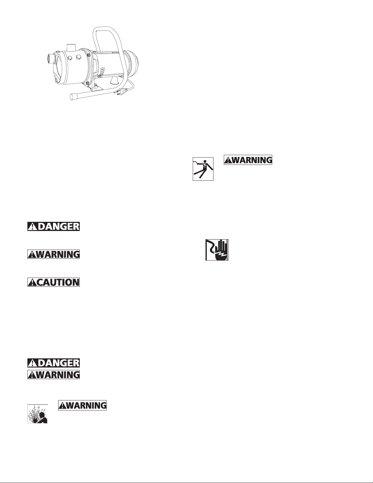
PORTABLE LAWN
SPRINKLER AND UTILITY
PUMP
Description
This pump is designed to sprinkle lawns and small
gardens from lakes, ponds, or rivers, empty or fill
stock tanks, remove standing water from flooded
areas, transfer water or boost water pressure.
Flammable liquids such as gasoline, chemicals or
corrosive liquids should never be used with this pump.
Safety Guidelines
This manual contains information that is very
important to know and understand. This information
is provided for SAFETY and to PREVENT EQUIPMENT
PROBLEMS. To help recognize this information,
observe the following symbols.
Danger indicates an imminently
hazardous situation which, if not avoided, will result
in death or serious injury.
Warning indicates a potentially
hazardous situation which, if not avoided, could result
in death or serious injury.
Caution indicates a potentially
hazardous situation, which, if not avoided, may result
in minor or moderate injury.
NOTE: Indicates important information, that if not
followed, may cause damage to equipment.
General Safety Information
1. Read these rules and instructions carefully. Failure
to follow these instructions could cause serious
bodily injury and/or property damage.
This pump is non-submersible.
This product contains chemicals
known to the State of California to cause cancer and
birth defects or other reproductive harm.
Pump only clear water.
Do not pump flammable or explosive fluids
such as gasoline, fuel oil, kerosene, etc. Do
not use in a flammable and/or explosive
atmosphere. Personal injury and/or property damage
could result.
NOTE: This pump is not designed to handle salt water,
brine, laundry discharge or any other application
which may contain caustic chemicals and/or foreign
materials. Pump damage could occur if used in these
applications and will void warranty.
All wiring must be
performed by a qualified electrician. The
pump must be installed in compliance with
all local and national codes.
2. Connect this product to a grounded circuit
equipped with a ground fault circuit interruptor
(GFCI) device.
3. Before installing this product, have the electrical
circuit checked by an electrician to ensure proper
grounding.
4.
5. Be sure the water source and piping are clear of
sand, dirt and scale. Debris will clog pump and
void warranty.
6. Failure to protect pump and piping from freezing
could cause severe damage and will void the
warranty.
7. Do not run pump dry.
BE CERTAIN the pump power source
is disconnected before installing or
servicing pump.
Installation
PUMPING FROM LAKES, PONDS OR SMALL STREAMS
1. Locate pump as close as possible to the water
source, keeping the vertical distance from the
water to pump as small as possible. Place pump
on level support. Protect against flooding and
excessive moisture.
2. Long lengths of pipe or hose and use of many
fittings will reduce pump flow. Use the smallest
number of fittings and shortest possible length of
pipe or hose.
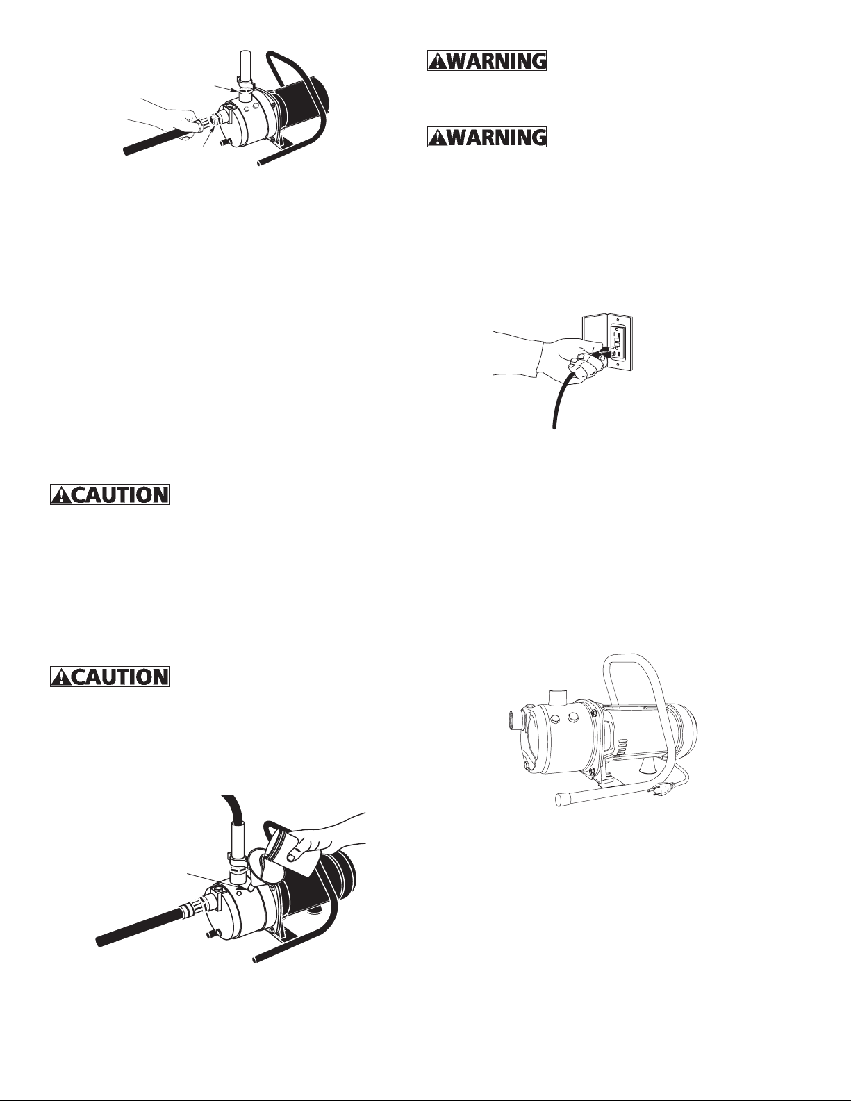
4. Connect inlet pipe or hose to pump. The inlet
connection is designed for 1” NPT thread. Rigid
pipe such as PVC will work fine for inlet and outlet
pipe. (Reminder: Minimize length of pipe and
number of fittings.) An adapter for garden hose is
included (see Figure 1).
1
© 2011. All rights reserved.
Page 2
Risk of electrical shock! This pump
O pmuP
teltu
is supplied with a grounding conductor and grounding
type attachment plug. Use a grounded receptacle to
reduce the risk of fatal electric shock.
telnI pmuP
Figure 1
IL0455
NOTE: The inlet hose must be a reinforced type when
pumping from lakes, ponds, or small streams. Regular
garden hose will collapse and lead to pump failure.
5. A foot valve with strainer should be used to
maintain prime during operation.
6. Seal all connections in the inlet hose. An air leak in
the fittings, hose, pipe or connections will draw air
even though no water leaks out. These inlet leaks
will reduce pump performance and lead to pump
failure.
7. Connect outlet pipe or hose to pump. The outlet
connection is designed for 1” NPT thread. Rigid
pipe such as PVC or garden hose may be used. An
adapter to garden hose thread is included (Figure
1).
BOOSTING WATER PRESSURE
Do not run pump with outlet pipe
or nozzle closed. The hose may burst from excessive
pressure. Use only reinforced high-pressure hose or
pipe for outlet pipe.
1. Connect inlet pipe or hose to pump. An adapter to
garden hose thread is included (Figure 1).
2. Connect the other end of inlet line to water supply.
3. Connect outlet pipe, or hose to pump.
Operation
Never cut off the round grounding
prong on the power cord. Cutting the cord or plug
will make the pump unsafe to operate and void the
warranty.
2. Turn the pump switch to the “off” position.
3. This pump is only for use on 120 volt (single
phase), 60 Hz, 15 amp service and is equipped with
a 3-conductor cord and e-prong, grounding type
plug. Insert power cord directly into GFCI outlet
(see Figure 3).
IL0459
Figure 3
4. Turn pump switch to the “on” position (see Figure
4). If the pump does not pump water within 5
minutes, turn off pump and refill with clean water.
If the pump does not operate after repeated
attempts, check the following:
- Vertical distance of pump to water level must not
be over 20 feet.
- Suction line must be airtight.
- All valves in suction and discharge line must be
open.
Never run the pump dry. Running
pump without water will cause seal failure. Fill pump
with water before starting.
1. Remove priming port on pump and fill with water.
Reinstall priming port on pump (see Figure 2). For
boosting water pressure: Do not remove priming
port. Turn on water supply.
Priming
troP
s
Figure 2
© 2011. All rights reserved.
IL0458
Maintenance
Maintain adequate ventilation for the pump motor.
The motor bearings are permanently lubricated at the
factory. Additional lubrication is not required.
DRAINING FOR WINTER
Always protect pump and piping against freezing
temperatures. If there is any danger of freezing, drain
the system.
1. Disconnect suction and discharge lines from
pump.
2
Page 3

2. Remove plug from lower front face of pump.
3. Drain all piping below the frost line, or store piping
indoors.
4. Store pump indoors.
See Figure 5 for replacement parts.
Troubleshooting Chart
SYMPTOM POSSIBLE CAUSE(S) CORRECTIVE ACTION
Motor will not run 1. Disconnect switch is off
2. Fuse is blown
3. Starting switch is defective
4. Wires at motor are loose, disconnected
or wired incorrectly.
Motor runs hot and overload kicks
off
Motor runs but no water is
delivered. NOTE: Check prime
before looking for other causes.
Unscrew priming plug and see if
water is in priming hole.
Pump does not deliver water to full
capacity
1. Motor is wired incorrectly
2. Voltage is too low
3. Pump house not properly vented
1. Pump in new installation did not pick
up prime through:
a. Improper priming
b. Air leaks
c. Leaking foot valve
2. Pump has lost prime through:
a. Air leaks
b. Water level below suction of pump
3. Impeller is plugged
4. Check valve or foot valve is stuck in
closed position
5. Pipes are frozen
6. Foot valve and/or strainer are buried in
sand or mud
1. Water level in well is lower than
estimated
2. Steel piping (if used) is corroded or
limed, causing excess friction
3. Piping is too small in size 3. Use larger piping
1. Be sure switch is on
2. Replace fuse
3. Replace starting switch
4. Refer to wiring instructions. Check and
tighten all wiring.
be hazardous. To discharge capacitor, touch
short capacitor terminals with an insulated
screwdriver. BE SURE to hold handle of
screwdriver while making contact with
capacitor terminals.
1. Refer to wiring instructions
2. Check with power company. Install heavier
wiring if wire size is too small (See Wiring
Chart).
3. Be sure pump has sufficient ventilation to
cool the motor
New Installation:
a. Re-prime according to instructions
b. Check all connections on suction line
c. Replace foot valve
2. Existing Installations:
a. Check all connections on suction line and
shaft seal
b. Lower suction line into water and re-prime.
If receding water level in well exceeds
suction lift, a deep well pump is needed
3. Clean impeller
4. Replace check valve or foot valve
5. Thaw pipes. Bury pipe below frost line. Heat
pit or pump house
6. Raise foot valve and/or strainer above well
bottom
1. A deep well jet pump may be needed (over
25 ft. (7.6M) to water)
2. Replace with plastic pipe where possible,
otherwise with new steel pipe
Capacitor voltage may
3
© 2011. All rights reserved.
Page 4

REPLACEMENT PARTS LIST
MODEL HSPJ100, SPJ100
1
2
3
4
6
7
5
IL0456
Ref. No. Description Part Number Qty.
*1 Shaft seal and gasket
*2 Impeller 1
*3 Diffuser 1
Kit #021337
*4 Nozzle assembly 1
5 Pump housing 021334 1
6 Large plug & O-Ring 021335 1
7 Small Plug & O-Ring 021336 3
*Purchase as a kit. Order #021337.
1
ONE YEAR LIMITED WARRANTY
This product is warranted for one year from the date of purchase or two
years from the date of manufacture, whichever occurs first. Subject to the
conditions hereinafter set forth, the manufacturer will repair or replace to the
original consumer, any portion of the product which proves defective due to
defective materials or workmanship. To obtain warranty service, contact the
dealer from whom the product was purchased. The manufacturer retains
the sole right and option to determine whether to repair or replace defective
equipment, parts or components. Damage due to conditions beyond the
control of the manufacturer is not covered by this warranty.
THIS WARRANTY WILL NOT APPLY: (a) To defects or malfunctions
resulting from failure to properly install, operate or maintain the unit in
accordance with printed instructions provided; (b) to failures resulting
from abuse, accident or negligence or use of inappropriate chemicals or
additives in the water; (c) to normal maintenance services and the parts
used in connection with such service; (d) to units which are not installed in
accordance with normal applicable local codes, ordinances and good trade
practices; and (e) the unit is used for purposes other than for what it was
designed and manufactured.
RETURN OF WARRANTED COMPONENTS: Any item to be repaired
or replaced under this warranty must be returned to the manufacturer at
Kendallville, Indiana or such other place as the manufacturer may designate,
freight prepaid.
© 2011. All rights reserved.
THE WARRANTY PROVIDED HEREIN IS IN LIEU OF ALL OTHER
EXPRESS WARRANTIES, AND MAY NOT BE EXTENDED OR MODIFIED
BY ANYONE. ANY IMPLIED WARRANTIES SHALL BE LIMITED TO THE
PERIOD OF THE LIMITED WARRANTY AND THEREAFTER ALL SUCH
IMPLIED WARRANTIES ARE DISCLAIMED AND EXCLUDED. THE
MANUFACTURER SHALL NOT, UNDER ANY CIRCUMSTANCES, BE
LIABLE FOR INCIDENTAL, CONSEQUENTIAL OR SPECIAL DAMAGES,
SUCH AS, BUT NOT LIMITED TO DAMAGE TO, OR LOSS OF, OTHER
PROPERTY OR EQUIPMENT, LOSS OF PROFITS, INCONVENIENCE
, OR OTHER INCIDENTAL OR CONSEQUENTIAL DAMAGES OF ANY
TYPE OR NATURE. THE LIABILITY OF THE MANUFACTURER SHALL
NOT EXCEED THE PRICE OF THE PRODUCT UPON WHICH SUCH
LIABILITY IS BASED.
This warranty gives you specific legal rights, and you may have other rights
which vary from state to state. Some states do not allow limitations on
duration of implied warranties or exclusion of incidental or consequential
damages, so the above limitations may not apply to you.
WARRANTY VALID IN CANADA AND MEXICO.
4
 Loading...