

Star HSP7000 SERIES Hardware Manual

HYBRID PRINTER
HSP7000 SERIES
Hardware Manual

“This device complies with Part 15 of the FCC Rules. Operation is subject to the following two conditions:
(1) This device may not cause harmful interference, and (2) this device must accept any interference received,
including interference that may cause undesired operation.”
Federal Communications Commission
Radio Frequency Interference
Statement
This equipment has been tested and found to comply with the limits for a Class B digital device, pursuant to Part
15 of the FCC Rules. These limits are designed to provide reasonable protection against harmful interference
when the equipment is operated in a commercial environment. This equipment generates, uses and can radiate radio frequency energy and, if not installed and used in accordance with the instruction manual, may cause harmful
interference to radio communications. Operation of this equipment in a residential area is likely to cause harmful
interference in which case the user will be required to correct the interference at his own expense.
For compliance with the Federal Noise Interference Standard, this equipment requires a shielded cable.
This statement will be applied only for the printers marketed in U.S.A.
Statement of
The Canadian Department of Communications
Radio Interference Regulations
This digital apparatus does not exceed the Class A limits for radio noise emissions from digital apparatus set out
in the Radio Interference Regulations of the Canadian Department of Communications.
Le présent appareil numérique n’émet pas de bruits radioélectriques dépassant les limites applicables aux appareils numériques de la classe A prescrites dans le Règlement sur le brouillage radioélectrique édicté par le ministère des Communications du Canada.
The above statement applies only to printers marketed in Canada
CE
Manufacturer’s Declaration of Conformity
EC Council Directive 89/336/EEC of 3 May 1989
This product, has been designed and manufactured in accordance with the International Standards EN 610006-3 / 2001 and EN 55024 / 1998, following the provisions of the Electro Magnetic Compatibility Directive of
the European Communities as of May 1989.
EC Council Directive 73/23/EEC and 93/68/EEC of 22 July 1993
This product, has been designed and manufactured in accordance with the International Standards EN 609501, following the provisions of the Low Voltage Directive of the European Communities as of 2001.
The above statement applies only to printers marketed in EU.
Trademark acknowledgments
HSP7000: Star Micronics Co., Ltd.
Notice
• All rights reserved. Reproduction of any part of this manual in any form whatsoever, without STAR’s ex-
press permission is forbidden.
• The contents of this manual are subject to change without notice.
• All efforts have been made to ensure the accuracy of the contents of this manual at the time of going to
press. However, should any errors be detected, STAR would greatly appreciate being informed of them.
• The above notwithstanding, STAR can assume no responsibility for any errors in this manual.
© Copyright 2008 Star Micronics Co., LTD.

TABLE OF CONTENTS
1. Unpacking and Installation .....................................................................................................................1
1-1. Unpacking ....................................................................................................................................1
1-2. Choosing a place for the printer ...................................................................................................
2
1-3. Removing the protective materials ...............................................................................................
3
2. Parts Identification and Nomenclature ..................................................................................................4
3. Setup ..........................................................................................................................................................5
3-1. Connecting the Cable to the PC ...................................................................................................
5
3-2. Connecting the Cable to the Printer .............................................................................................
7
3-3. Installing the Printer Software ...................................................................................................
11
3-4. Connecting the Optional AC Adapter ........................................................................................
12
3-5. Turning Power On ......................................................................................................................
13
3-6. Switch Cover Installation ...........................................................................................................
14
3-7. Connecting to a Peripheral Unit .................................................................................................
15
3-8. Attaching the Interface Cover ....................................................................................................
16
4. Loading the Ribbon Cartridge and Paper ...........................................................................................17
4-1. Loading the Ribbon Cartridge ...................................................................................................
17
4-2. Loading the Paper Roll ..............................................................................................................
18
4-3. Loading the Slip Paper or Validation Paper ...............................................................................
20
4-4. Scanning MICR Characters .......................................................................................................
21
5. Consumable Parts and AC Adapter .....................................................................................................24
5-1. Thermal Paper Roll ....................................................................................................................
24
5-2. Slip Paper ...................................................................................................................................
26
5-3. AC adapter (option)
....................................................................................................................27
6. Control Panel and Other Functions .....................................................................................................28
6-1. Control Panel
..............................................................................................................................28
6-2. Errors ..........................................................................................................................................29
6-3. Self-Printing ...............................................................................................................................31
7. Adjusting the Near-end Sensor .............................................................................................................33
8. Preventing and Clearing Paper Jams ...................................................................................................35
8-1. Preventing Paper Jams ...............................................................................................................
35
8-2. Removing Paper Jam .................................................................................................................
35
8-3. Releasing a Locked Cutter .........................................................................................................
37
9. Maintenance ...........................................................................................................................................38
9-1. Cleaning the Thermal Head .......................................................................................................
38
9-2. Cleaning the Rubber Roller .......................................................................................................
38
9-3. Cleaning the Impact Platen ........................................................................................................
38
9-4. Cleaning the Sensors and the Surrounding Area ........................................................................
38
9-5. Cleaning the Paper Holder and the Surrounding Area ...............................................................
39
10. Specifications ........................................................................................................................................40
10-1. General Specifications ...............................................................................................................
40
10-2. Auto Cutter Specifications .........................................................................................................
41
10-3. MICR Specifications (Slip Printer) ............................................................................................
41
10-4. External Specifications ...............................................................................................................
41
10-5. Interface Specifications ..............................................................................................................
42
10-6. Electrical Characteristics (AC adapter) ......................................................................................
43
10-7. Environmental Requirements .....................................................................................................
44

10-8. Reliability Specifications ...........................................................................................................45
11. Dip Switch Setting ................................................................................................................................46
11-1. Parallel Interface Model .............................................................................................................
47
11-2. RS-232C Interface Model ..........................................................................................................
48
11-3. USB/PoweredUSB Interface Model ..........................................................................................
50
11-4. Ethernet Interface Model ...........................................................................................................
51
12. Parallel Interface ..................................................................................................................................53
13. RS-232C Serial Interface .....................................................................................................................54
13-1. Interface Specifications ..............................................................................................................
54
13-2. RS-232C Connector ...................................................................................................................
55
13-3. Cable Connections .....................................................................................................................
56
14. USB and Ethernet ................................................................................................................................57
14-1. USB/PoweredUSB Interface Specifications ...............................................................................
57
14-2. Ethernet Interface Specifications ................................................................................................
57
15. Peripheral Unit Drive Circuit .............................................................................................................58
16. Memory Switch Settings ......................................................................................................................60
Please access the following URL
http://www.star-m.jp/eng/dl/dl02.htm
for the latest revision of the manual.
– 1 –
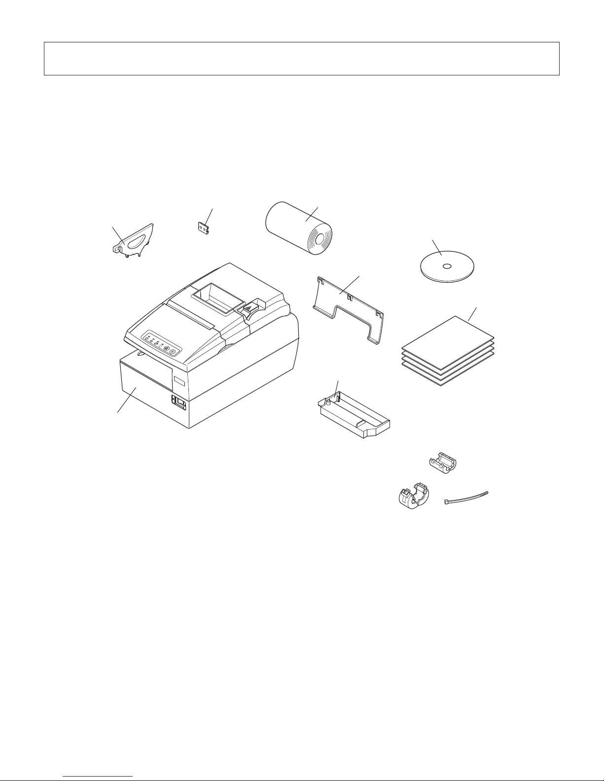
1. Unpacking and Installation
1-1. Unpacking
After unpacking the unit, check that all the necessary accessories are included in the package.
Note: The ferrite core and fastener provided with your
printer depend on your printer conguration.
Fig. 1-1 Unpacking
If anything is missing, contact the dealer where you bought the printer and ask them to supply
the missing part. Note that it is a good idea to keep the original box and all the packing materials
just in case you need to pack the printer up again and send it somewhere at a later date.
Note
Printer
Paper roll
Switch blind
Setup sheets
CD-ROM
Paper guide
P
O
W
E
R
E
R
R
O
R
P
A
P
E
R
O
U
T
S
L
I
P
F
E
E
D
R
E
L
E
A
S
E
Interface cover
Ribbon cassette

– 2 –
1-2. Choosing a place for the printer
Before actually unpacking the printer, you should take a few minutes to think about where
you plan to use it. Remember the following points when doing this.
P Choose a rm, level surface where the printer will not be exposed to vibration.
P The power outlet you plan to connect to for power should be nearby and unobstructed.
P Make sure that the printer is close enough to your host computer for you to connect
the two.
P Make sure that the printer is not exposed to direct sunlight.
P Make sure that the printer is well away from heaters and other sources of extreme
heat.
P Make sure that the surrounding area is clean, dry, and free of dust.
P Make sure that the printer is connected to a reliable power outlet. It should not be on
the same electric circuit as copiers, refrigerators, or other appliances that cause power
spikes.
P Make sure that the room where you are using the printer is not too humid.
WARNING
P Shut down your equipment immediately if it produces smoke, a strange odor, or unu-
sual noise. Immediately unplug the equipment and contact your dealer for advice.
P Never attempt to repair this product yourself. Improper repair work can be dangerous.
P Never disassemble or modify this product. Tampering with this product may result in
injury, re, or electric shock.
– 3 –
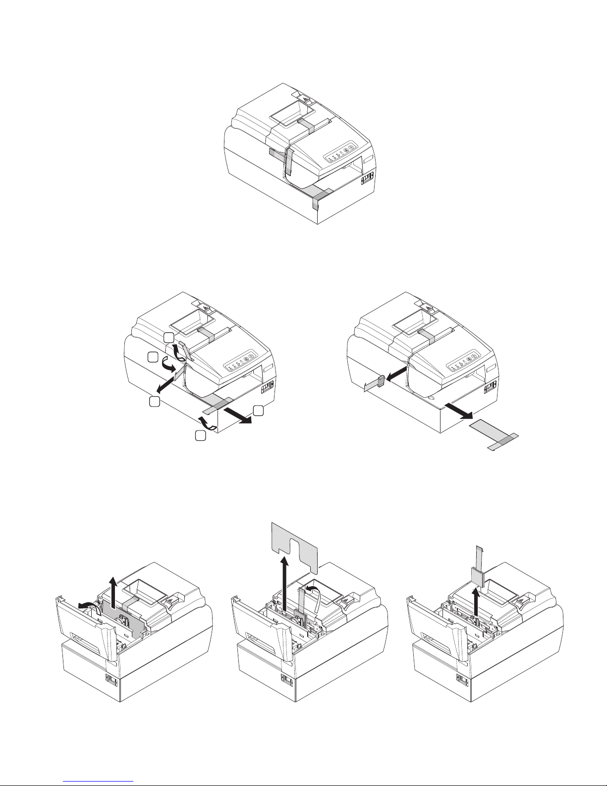
1-3. Removing the protective materials
Four protective materials are inserted into the printer to protect components during shipping.
Before using the printer, be sure to remove all protective materials as shown in the illustration.
(1) Remove the three tapes and pull the two protective sheets.
(2) Open the front cover. Remove the tape, pull the protective sheet straight.
Pull the protective sheet, which is securing the head in place, straight up and out of the unit.
Then, remove the tape and pull the protective sheet, which is located between the head and
the platen, straight out of the unit.
Note: that it is a good idea to keep all protective materials in case you will need to pack
the printer up again and send it somewhere at a later date.
P
O
W
E
R
E
R
R
O
R
P
A
P
E
R
O
U
T
S
L
I
P
F
E
E
D
R
E
L
E
A
S
E
1
1
1
2
2
P
O
W
E
R
E
R
R
O
R
P
A
P
E
R
O
U
T
S
L
I
P
F
E
E
D
R
E
L
E
A
S
E
P
O
W
E
R
E
R
R
O
R
P
A
P
E
R
O
U
T
S
L
I
P
F
E
E
D
R
E
L
E
A
S
E
– 4 –
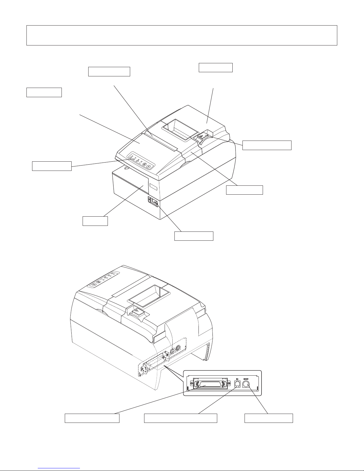
2. Parts Identication and Nomenclature
P
O
W
E
R
E
R
R
O
R
P
A
P
E
R
O
U
T
S
L
I
P
F
E
E
D
R
E
L
E
A
S
E
P
O
W
E
R
E
R
R
O
R
P
A
P
E
R
O
U
T
S
L
I
P
F
E
E
D
R
E
L
E
A
S
E
Power switch
Used to turn on/off
power to the printer.
Interface connector
For connection to a
host computer.
Validation slot
Insert paper here.
Front cover
Open it to replace the ribbon.
Do not open it during printing.
Slip slot
Insert paper here.
Rear cover
Open it to replace the roll paper.
Do not open it during printing.
Cutter cover
Open it to clear paper jam. Do not
open it during printing.
Control panel
Features LED indicators
to indicate printer status
and switches to operate
the printer.
Cover open lever
Push this lever in the direction of the
arrow to open the printer cover.
Peripheral drive connector
Connects to peripheral units such
as cash drawers, etc.
Do not connect this to a telephone.
Power connector
For connection of the AC adapter.
Never unplug the AC adapter while
the printer is on.
– 5 –
3. Setup
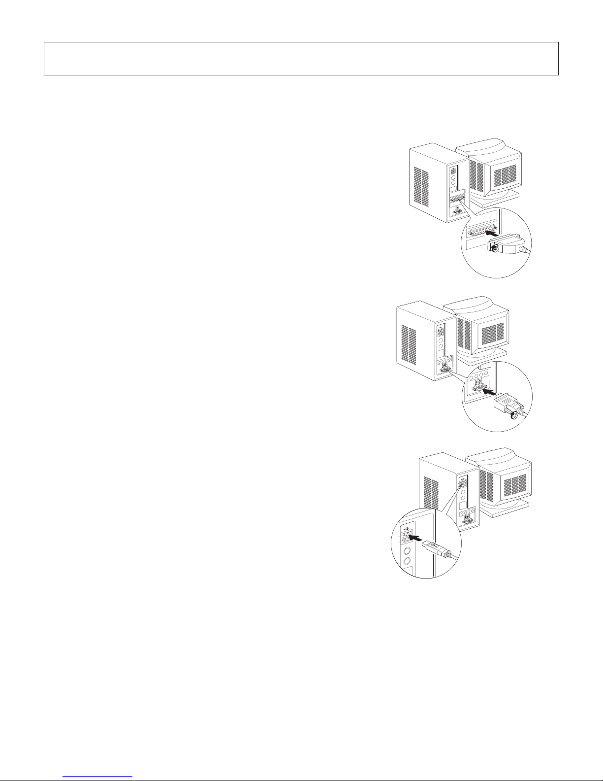
3-1. Connecting the Cable to the PC
3-1-1. Parallel Interface Cable
Connect the parallel interface cable to a parallel port
of your PC.
3-1-2. RS-232C Interface Cable
Connect the RS-232C interface cable to a RS-232C
port of your PC.
3-1-3. USB Interface Cable
Connect the USB interface cable to a USB port of
your PC.
– 6 –
3-1-4. PoweredUSB Interface Cable
Attach the ferrite core to the PoweredUSB interface cable, and connect the cable to a PoweredUSB port of your PC.
Recommended Cable: 30729130 POWERED USB CABLE 1X8LNL 1.2M
Recommended PCI Card: PCI to 4 Port PoweredUSB Card
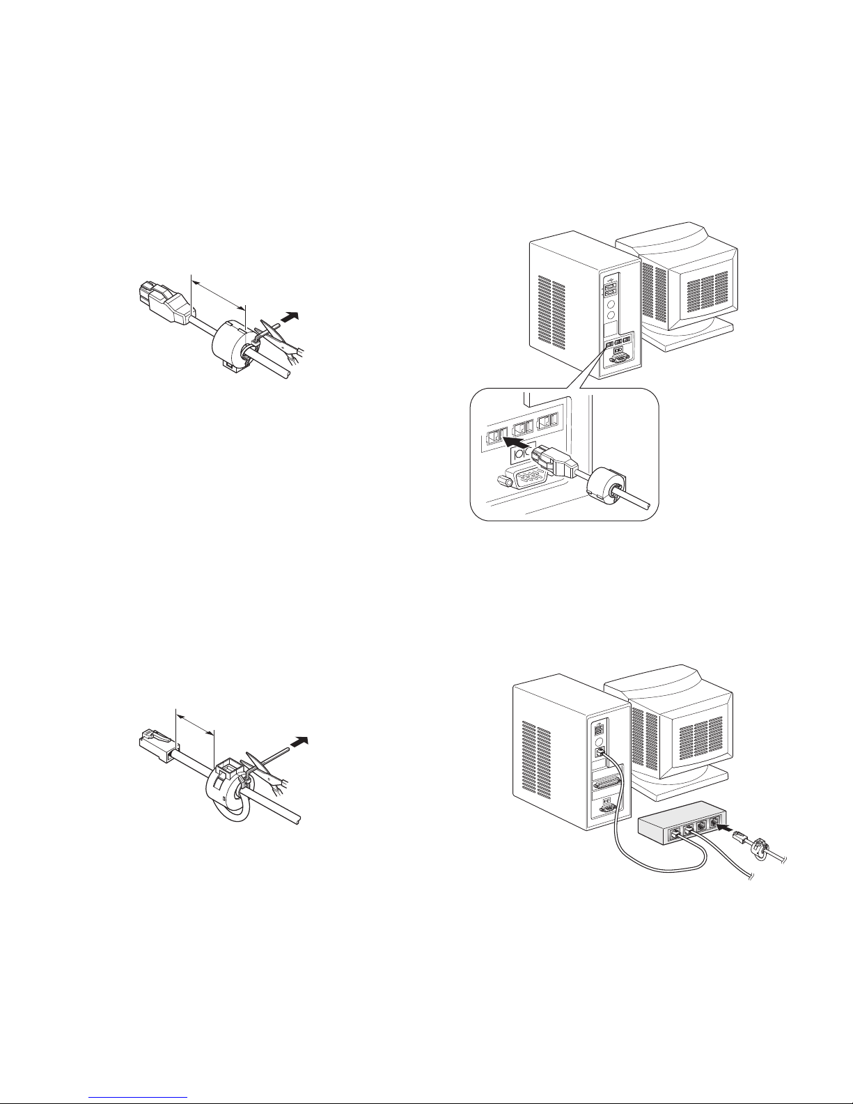
3-1-5. Ethernet Interface cable
Attach the ferrite core to the ethernet interface cable, and connect the cable to a ethernet port
of your PC.
Maximum 3.5 cm
Pull and cut
Pull and cut
Maximum 10 cm

– 7 –
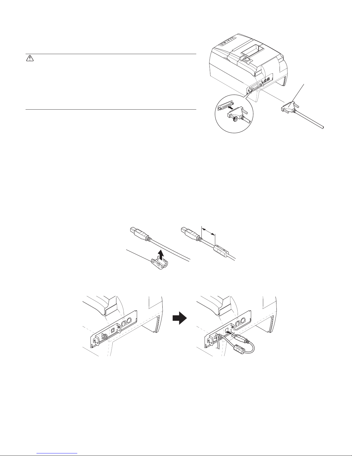
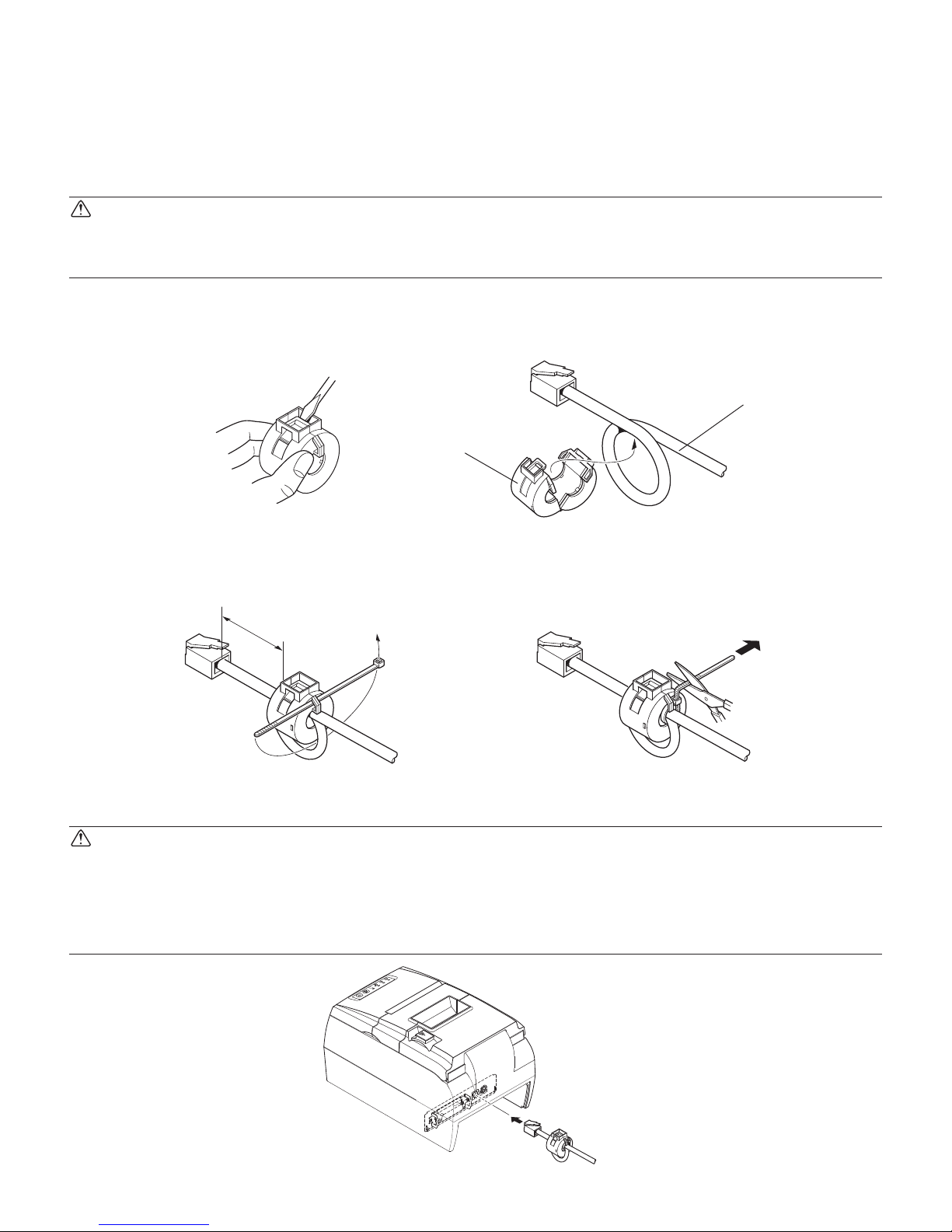
3-2-1. Parallel Interface Cable
(1) Make sure the printer is turn off.
(2) Afx the ferrite core onto the cable as shown in
the illustration.
(3) Pass the fastener through the ferrite core.
(4) Loop the fastener around the cable and lock it.
Use scissors to cut off any excess.
(5) Connect the interface cable to the connector on
the rear panel of the printer.
(6) Fasten the connector clasps.
3-2. Connecting the Cable to the Printer
Note that the interface cable is not provided. Please use a cable that meets specications.
CAUTION
Before connecting/disconnecting the interface cable, make sure that power to the printer and
all the devices connected to the printer is turned off. Also make sure the power cable plug is
disconnected from the AC outlet.
Ferrite core
Interface cable
5 cm
(maximum)
Fastener
P
O
W
E
R
E
R
R
O
R
P
A
P
E
R
O
U
T
S
L
I
P
F
E
E
D
R
E
L
E
A
S
E
Parallel interface
cable
– 8 –
3-2-2. RS-232C Interface Cable
(1) Make sure the printer is turn off.
CAUTION
Before connecting/disconnecting the interface cable, make sure that power to the printer and all the
devices connected to the printer is turned off. Also
make sure the power cable plug is disconnected
from the AC outlet.
(2) Connect the interface cable to the connector on
the rear panel of the printer.
(3) Tighten the connector screws.
3-2-3. USB Interface Cable
Afx the ferrite core onto the USB cable as shown in the illustration below and make sure to
pass the cable through the cable support as shown in the illustration.
Recommended Cable: 30729100 USB CABLE 1.8M TSP1
P
O
W
E
R
E
R
R
O
R
P
A
P
E
R
O
U
T
S
L
I
P
F
E
E
D
R
E
L
E
A
S
E
RS-232C
interface
cable
Ferrite core
4 cm (Maximum)
– 9 –
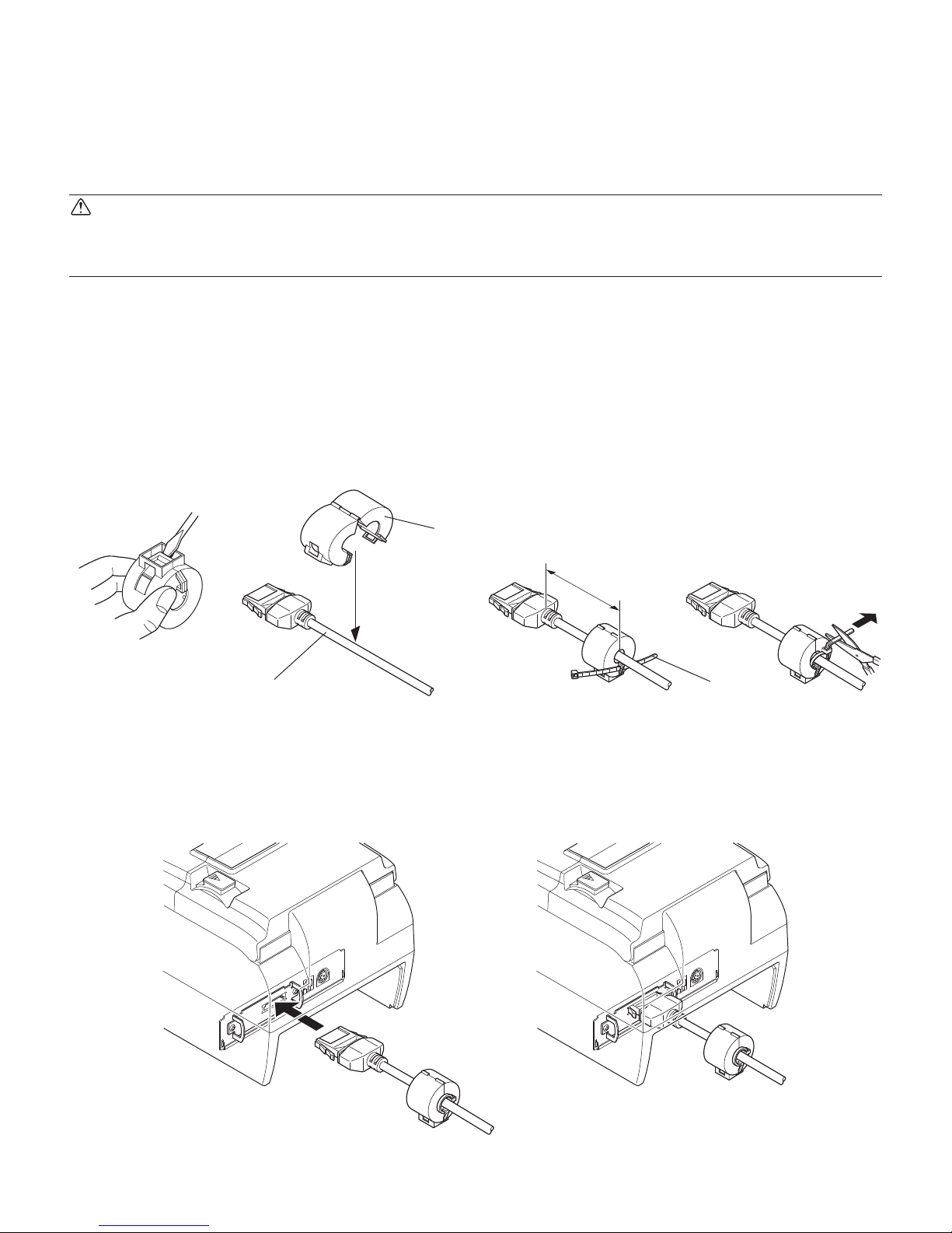
3-2-4. PoweredUSB Interface Cable
(1) Turn the power switch off.
(2) If connected to an AC adapter, pull the power cord plug from the outlet and then pull the
plug from the power connector on the printer side.
CAUTION
If connecting a PoweredUSB cable, do not connect the AC adapter because this can cause a
malfunction.
(3) Afx the ferrite core onto the cable as shown in the illustration.
Recommended Cable : 30729130 POWERED USB CABLE 1X8LNL 1.2M
(4) Pass the fastener through the ferrite core.
(5) Loop the fastener around the cable and lock it.
Use scissors to cut off any excess.
(6) Connect the interface cable to the connector on the rear panel of the printer.
Pull and cut
Ferrite core
Interface cable
Maximum
3.5 mm
Fastener
– 10 –
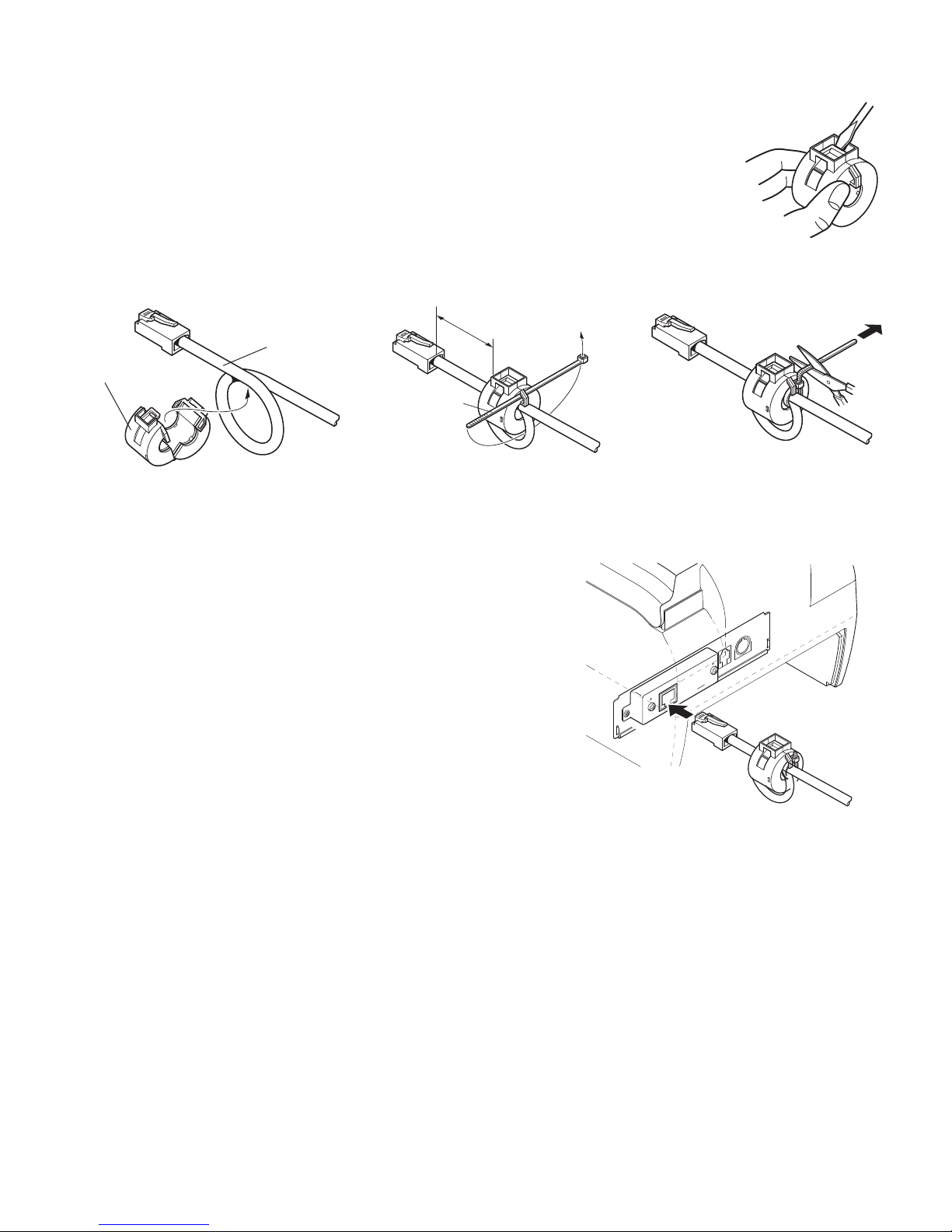
3-2-5. Connecting Ethernet Cable
(1) Make sure the printer is turned off.
(2) Afx the ferrite core onto the ethernet cable as
shown in the illustration below.
(3) Pass the fastener through the ferrite core.
(4) Loop the fastener around the cable and lock it.
Use scissors to cut off any excess.
(5) Connect the interface cable to the connector on
the rear panel of the printer.
Ferrite core
Ethernet cable
10 cm
(maximum)
Fastener
– 11 –
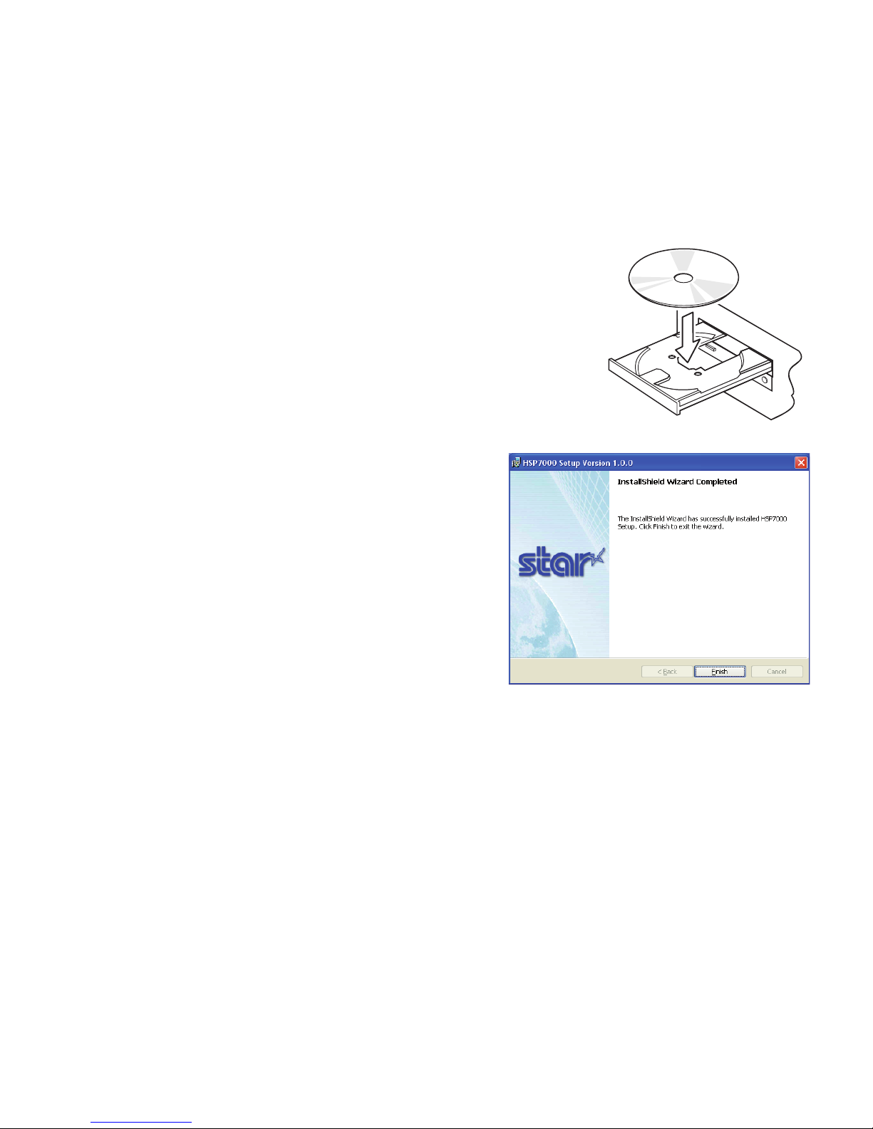
3-3. Installing the Printer Software
Here is the procedure for installing the printer driver and utility software, which are stored on
the supplied CD-ROM.
The procedure applies to the Windows operating systems shown below.
• Windows 2000
• Windows XP
• Windows Vista 32-Bit
(1) Turn ON the power to your PC to start Windows.
(2) Insert the supplied CD-ROM (Drivers and Utilities)
into the CD-ROM drive.
(3) Follow the instructions that appear on the screen.
(4) The dialog shown in the illustration indicates that
the procedure has been completed.
Click “Finish”.
The dialog that appears on the screen varies with your system. This completes the installation
of the printer software. A message will appear, prompting you to restart. Restart Windows.
For instruction on the Windows Vista 64-Bit, refer to the software manual located in the
“Documents” folders on the CD-ROM.
– 12 –
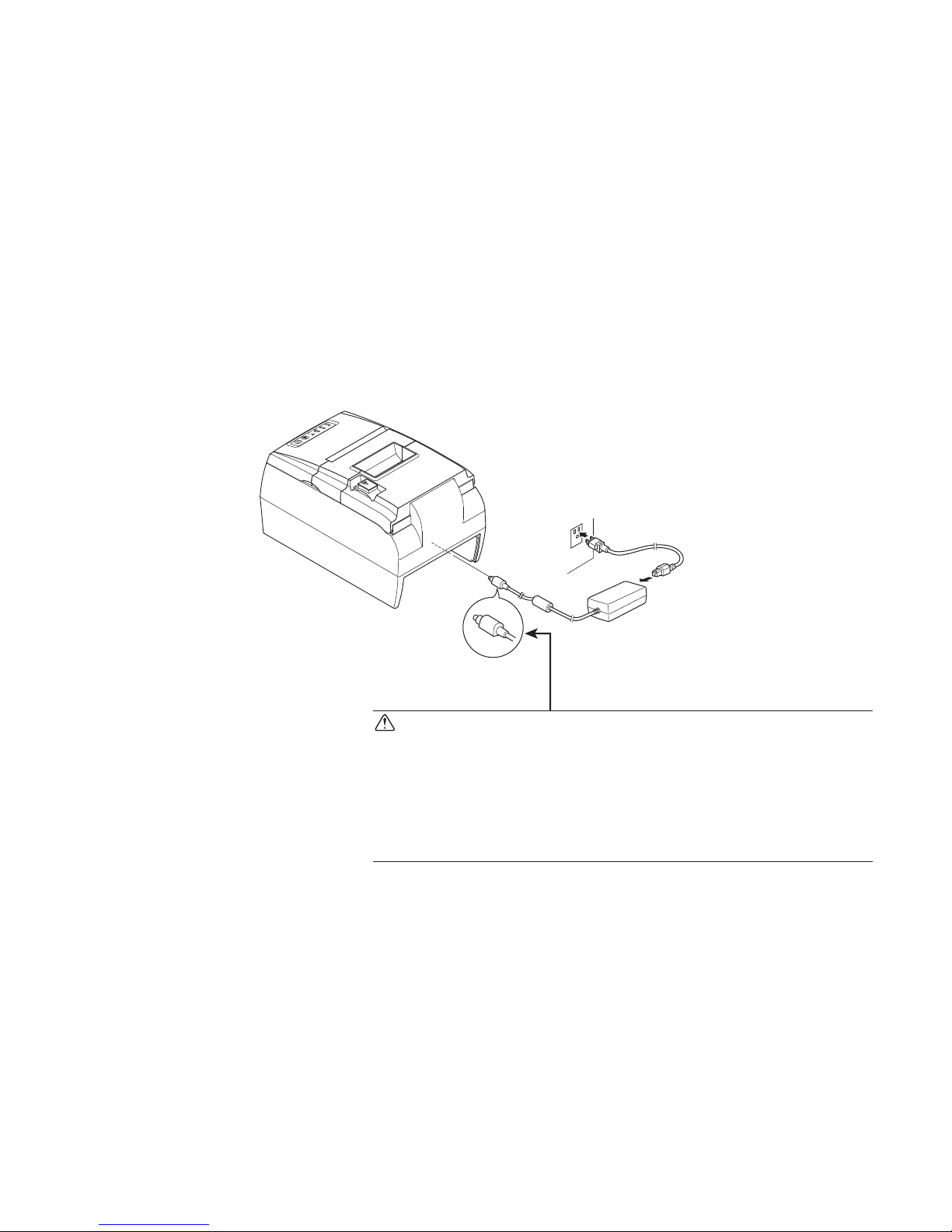
3-4. Connecting the Optional AC Adapter
Note: Before connecting/disconnecting the AC adapter, make sure that power to the printer
and all the devices connected to the printer is turned off. Also make sure the power
cable plug is disconnected from the AC outlet.
(1) Connect the AC adapter to the power cable.
Note: Use only the standard AC adapter and power cable.
(2) Connect AC adapter to the connector on the printer.
(3) Insert the power cable plug into an AC outlet.
CAUTION
When disconnecting the cable, take hold of the cable
connector to pull it out. Releasing the lock makes it easy
to disconnect the connector.
Pulling the cable excessively could cause damage to the
connector.
P
O
W
E
R
E
R
R
O
R
P
A
P
E
R
O
U
T
S
L
I
P
F
E
E
D
R
E
L
E
A
S
E
– 13 –
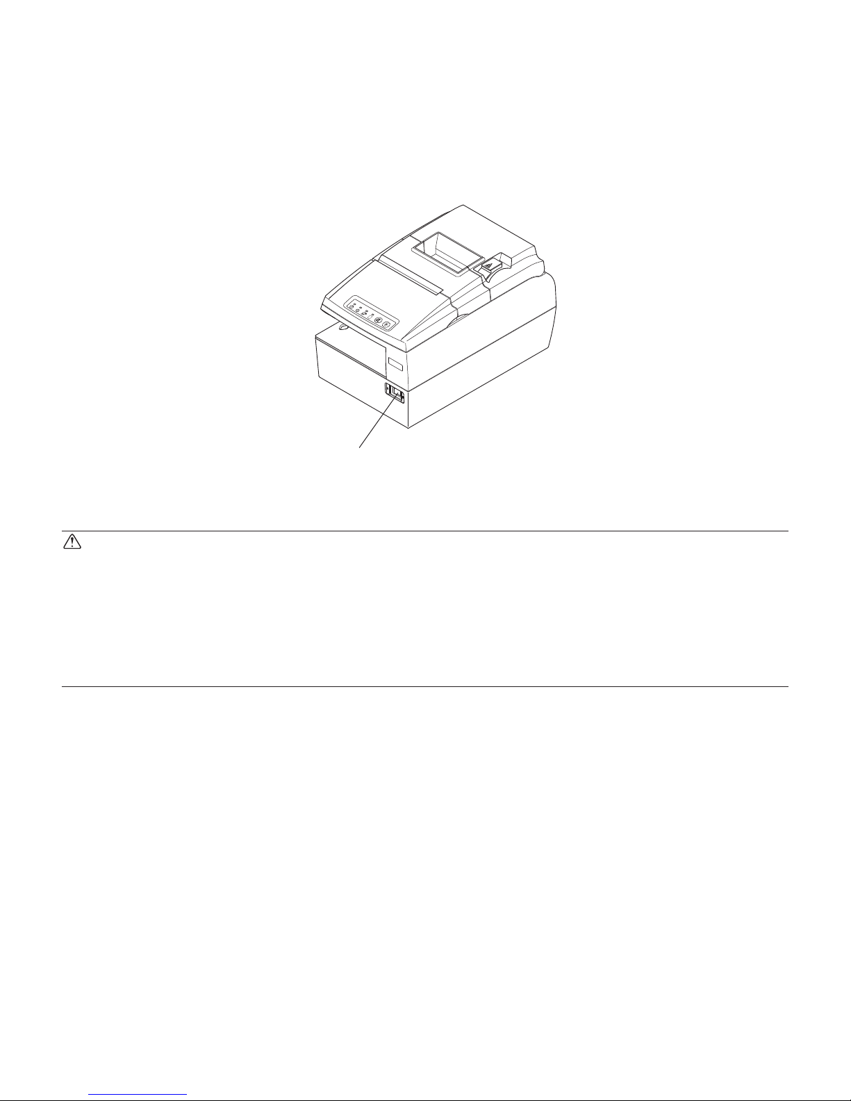
3-5. Turning Power On
Make sure that the Power cord has been connected as described in 3-4.
Turn ON the power switch located on the front of the printer.
The POWER lamp on the control panel will light up.
CAUTION
We recommend that you unplug the printer from the power outlet whenever you do not plan to
use it for long periods. Because of this, you should locate the printer so that the power outlet it
is plugged into is nearby and easy to access.
When an Switch blind is afxed to the printer above the power switch, the ON/OFF marks of
the power switch may be hidden. If this occurs, remove the power cord from the outlet to turn
the printer OFF.
Power switch
P
O
W
E
R
E
R
R
O
R
P
A
P
E
R
O
U
T
S
L
I
P
F
E
E
D
R
E
L
E
A
S
E
– 14 –
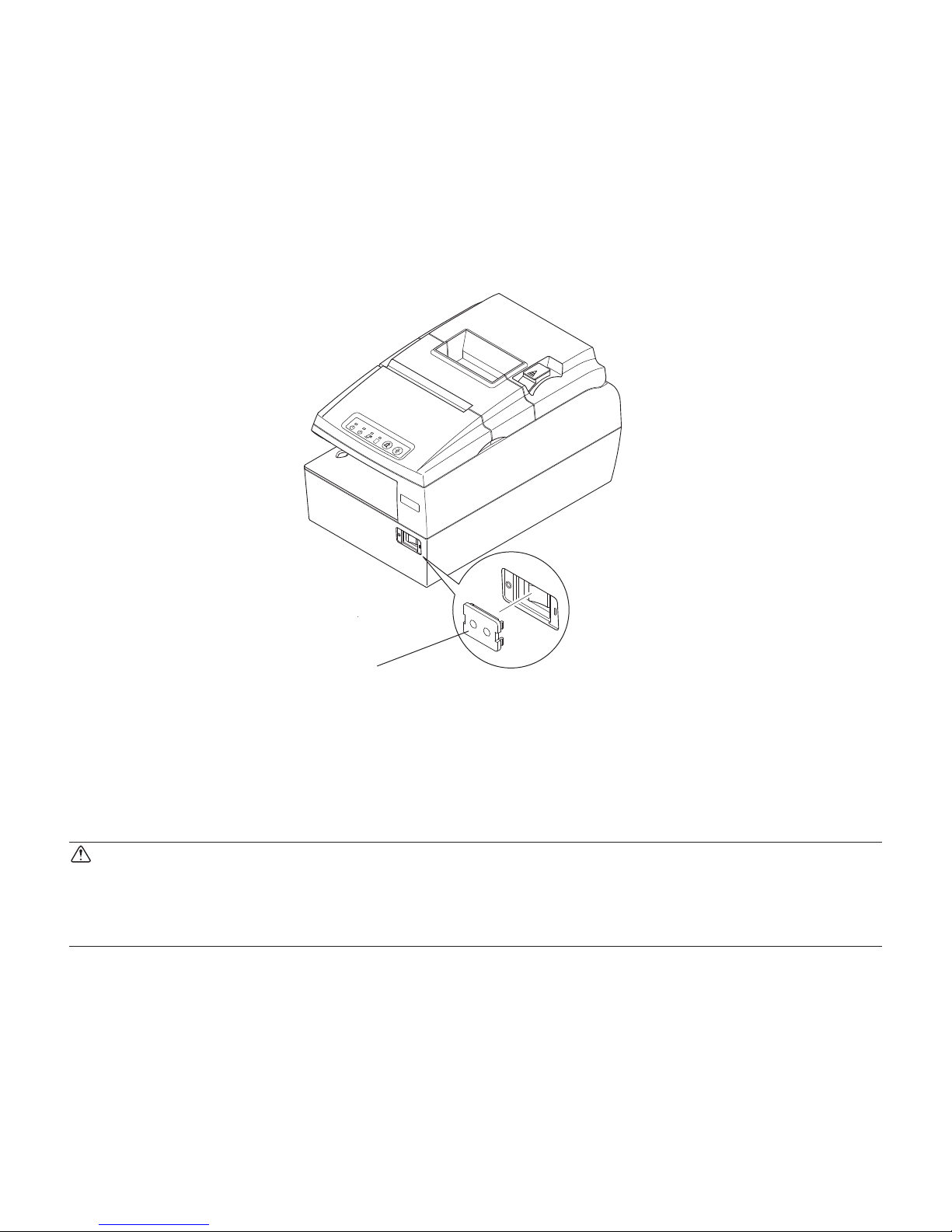
3-6. Switch Cover Installation
It is not necessary to install the switch cover. Only install it if it is necessary for you. By installing the switch cover, the following become possible.
• Preventing the power switch from being operated by mistake.
• Ensuring that other people can not easily operate the power switch.
Install the switch cover as shown in the diagram below.
The power switch can be turned ON ( | ) and OFF (O) by inserting a narrow instrument (ball
pen etc.) in the holes in the switch cover.
CAUTION
We recommend that you unplug the printer from the power outlet whenever you do not plan to
use it for long periods. Because of this, you should locate the printer so that the power outlet it
is plugged into is nearby and easy to access.
P
O
W
E
R
E
R
R
O
R
P
A
PER
O
U
T
S
L
I
P
F
E
E
D
R
E
L
E
A
S
E
Switch blind
– 15 –
3-7. Connecting to a Peripheral Unit
You can connect a peripheral unit to the printer using a modular plug. See “Modular plug” on
page 54 for details about the type of modular plug that is required. Note that this printer does
not come with a modular plug or wire, so it is up to you to obtain one that suits your needs.
CAUTION
Make sure that the printer is turned off and unplugged from the AC outlet and that the computer
is turned off before making connections.
(1) Make sure the printer is turned off.
(2) Afx the ferrite core onto the ethernet cable as shown in the illustration below.
(3) Pass the fastener through the ferrite core.
(4) Loop the fastener around the cable and lock it.
Use scissors to cut off any excess.
(5) Connect the peripheral drive cable to the connector on the rear panel of the printer.
CAUTION
Do not connect a telephone line into the peripheral drive connector. Failure to observe this may
result in damage to the printer.
Also, for safety purposes, do not connect wiring to the external drive connector if there is a
chance it may carry peripheral voltage.
P
O
W
E
R
E
R
R
O
R
P
A
P
E
R
O
U
T
S
L
I
P
F
E
E
D
R
E
L
E
A
S
E
Peripheral drive cable
Ferrite core
Pull and cut
10 cm (maximum)
– 16 –
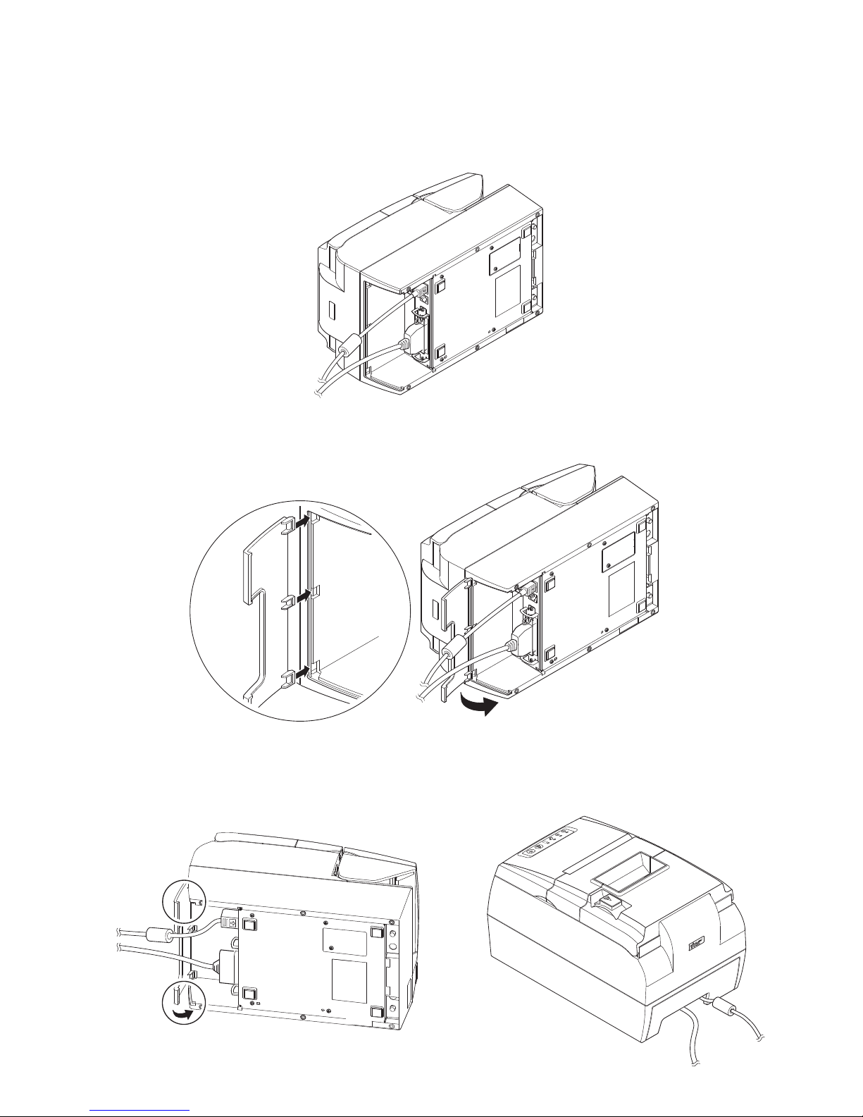
3-8. Attaching the Interface Cover
It is not necessary to attach the interface cover. Only attach it if it is necessary for you.
Attach the interface cover as shown in the illustration.
(1) Place the printer as shown below.
(2) Install the interface cover by aligning the tabs on the interface cover with the grooves in
the printer case.
(3) Place the AC cable and the interface cable in the cutout of the interface cover. Then, install
the interface cover until the both ends of the interface cover click into place.
P
O
W
E
R
E
R
R
O
R
P
A
P
E
R
O
U
T
S
L
I
P
F
E
E
D
R
E
L
E
A
S
E
 Loading...