

Page 1
LAWN SPRINKLER, IRRIGATION PUMP
STAR
110 West Division St. | Boonville, IN 47601
starwatersystems.com
®
MODEL #
HSP10P1, HSP15P1, HSP20P1
For installation videos and other
information, scan with your smart phone.
1. Pre-Installation
2. Tools required
3. General Pump Information
4. Pump and Pipe Assembly
5. Check your Breaker Box
6. Change voltage if required - Video
7. Wiring Instructions - Video
8. Pump Priming and Startup - Video
9. Irrigation System Controls
10. Care and Maintenance
Questions, problems, missing parts? Before returning to your retailer, call our customer
service department at 1-800-742-5044, 7:30 a.m.-5:00 p.m., EST, Monday-Friday.
023121 J
Page 2
SAFETY INFORMATION
Please read and understand this entire manual before attempting to assemble, operate or install the
product.
• NOTE: Pumps with the “UL” Mark and pumps with the “US” mark are tested to UL Standard
UL778.CSA certied pumps are certied to CSA Standard C22.2 No. 108. (CUS)
DANGER
ELECTRICAL SHOCK HAZARD.
Always disconnect power source before performing any work on or near the motor or its
connected load. If the power disconnect point is out-of-sight, lock it in the open position and tag it
to prevent unexpected application of power. Failure to do so could result in fatal electrical shock.
ELECTRICAL SHOCK HAZARD.
Do not handle the pump with wet hands or when standing in water as fatal electrical shock could
occur. Disconnect main power before handling unit for ANY REASON!
RISK OF ELECTRIC SHOCK.
These pumps have not been investigated for use in swimming pool areas.
WARNING
ELECTRICAL SHOCK ALERT.
Follow all local electrical and safety codes, as well as the National Electrical Code (NEC) and the
Occupational Safety and Health Act (OSHA).
ELECTRICAL SHOCK ALERT.
Replace damaged or worn wiring cord immediately.
ELECTRICAL SHOCK ALERT.
Do not kink power cable and never allow the cable to come in contact with oil, grease, hot surfaces,
or chemicals.
ELECTRICAL SHOCK ALERT.
Unit must be securely and adequately electrically grounded. This can be accomplished by wiring
the unit to a ground metal-clad raceway system or by using a separate ground wire connected to
the bare metal of the motor frame or other suitable means.
CHEMICAL ALERT.
This product contains chemicals known to the State of California to cause cancer and birth defects
or other reproductive harm.
CAUTION
ELECTRICAL SHOCK MAY OCCUR
Protect the power cable from coming in contact with sharp objects.
HOT SURFACE MAY CAUSE BURNS
Be careful when touching the exterior of an operating motor - It may be hot enough to be painful or cause injury.
PRODUCT DAMAGE MAY RESULT
Make certain that the power source conforms to the requirements of your equipment.
2
Page 3

PREPARATION
Before beginning installation of product, make sure all parts are present. Compare parts with package
contents drawing. If any part is missing or damaged, do not attempt to assemble the product. Contact
customer service for replacement parts.
Estimated Installation Time: 2 hours.
Tools Required for Assembly (not included): Hacksaw, Pipe Wrenches (2), Wire Strippers, Needle-
Nose Pliers, Phillips Screwdriver, Wire Cutters, Adjustable Wrench
Parts Required For Assembly (not included): 2 in. Sched 40 PVC pipe, 1-1/2 in. Sched 40 PVC
pipe, 2 in. MPT x 2 in. slip adaptor, 1-1/2 in. MPT x 1-1/2 in. slip adaptor, 1-1/2 in. pipe tee, 1-1/2 in.
slip x 1-1/4 in. FPT reducer bushing, 1-1/4 in. MPT plug, 2 in. 90º pipe elbow, 1-1/2 in. 90º pipe elbow,
thread tape, 1/4 in. electric wire strain relief, 2-step PVC glue system (primer and sealer), and thread
paste.
Optional Parts For Assembly (not included):
1. Priming Plug with Pressure Gauge: Used instead of a priming plug alone. Helps determine if
the pump is primed, indicates if the pump is operating properly and what kind of pressure is in the
system when operating.
(1) 1-1/4 in. MPT x 1/2 in. FPT reducer bushing
(1) 1/2 in. MPT x 1/4 in. FPT reducer bushing
(1) 100 PSI pressure gauge
2. Unions: Used for easy removal of the pump from the sprinkler system.
(2) 2 in. union
(1) 1-1/2 in. union
3. (1) 1-1/2 in. Ball Valve: Prevents back flow of water from the sprinkler system when the pump is
removed from the system.
4. 1-1/2 in. Couplers: Quantity determined by the total length of pipe used.
5. 2 in. Couplers: Quantity determined by the total length of pipe used.
3
Page 4
GENERAL PUMP INFORMATION
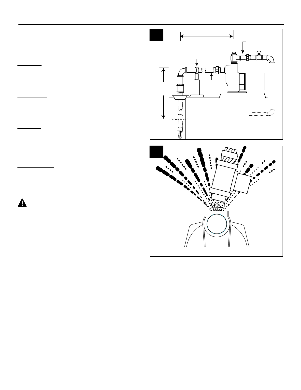
Typical Pump Setup
Typical setups for lawn sprinkler pump systems
include ground water wells (Fig. 1) or surface
water, such as lakes, ponds or streams. (Fig. 3)
Location
For best performance, the pump must be
located as close to the water source as possible
and protected from the elements.
Ventilation
Ventilation and drainage must be provided to
prevent damage to the motor from heat and
moisture.
Freezing
The pump and all piping must be protected from
freezing. If freezing weather is forecast, drain
pump or remove completely from the sprinkler
system.
Water Supply
The water source must be able to supply
enough water to satisfy the capacity of the pump
and water needs. See performance chart on
page 21.
1
Vertical
Lift
25 ft.
max
2
60 ft. max.
Inlet pipe to water
Pipe
Support
Inlet
Pipe
Water Level
Outlet
Pipe
Discharge to
Sprinkler System
WARNING: NEVER run pump (A) against a
closed discharge. Doing so can boil water inside
pump, causing hazardous pressure in unit, risk
of explosion and possibly scalding persons
handling pump. (Fig. 2)
4
Page 5
GENERAL PUMP INFORMATION
Valve
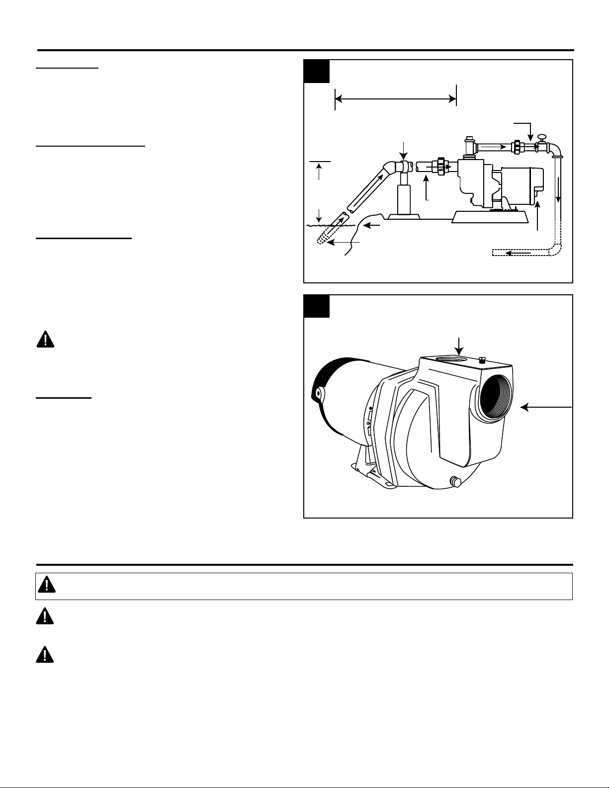
Vertical Lift
Vertical lift is the vertical distance from the
lowest level of the water to the pump intake. The
pump will move water as long as the pump is
within 25 vertical feet of the water source.
Horizontal Distance
The horizontal distance is the horizontal
measurement between the pump inlet and the
water source. This distance may affect the ability
of the pump to operate. If it is over 150 feet, call
customer service at 1-800-742-5044.
Pipe And Fittings
Use galvanized steel or NSF PW Schedule 40
PVC pipe and fittings. This material is designed
for water pressure and will seal against air
and water under pressure. Do Not Use: DWV
fittings, as these are designed for drains without
pressure and will not seal properly.
CAUTION: The entire system must be
air and water tight for efficient operation and to
maintain prime.
Wire Size:
The wire size is determined by the distance
from the breaker box to the pump motor, and
the horsepower rating of the motor. See the wire
chart on page 15 for proper wire size.
3
Vertical
Lift
25 ft.
max
4
60 ft. max.
Inlet pipe to water
Pipe
Support
Inlet
Pipe
Water Level
Foot
Discharge to
Sprinkler System
1-1/2 in. Discharge
Outlet Pipe
Motor Cover
2 in.
Suction
PUMP PREPARATION FOR WELL AND SURFACE WATER
CAUTION: Dry-t entire assembly to ensure proper t before gluing or taping parts.
CAUTION: Follow all proper gluing procedures as specied by the glue manufacturer. Always glue
in a vertical direction whenever possible to prevent glue from dripping inside pipe or ttings
CAUTION: Use thread tape and a thread paste compound on all male threads except for the
unions. Tighten securely with a wrench and add another 1/4 turn to ensure proper seal.
5
Page 6
PUMP PREPARATION FOR WELL AND SURFACE WATER
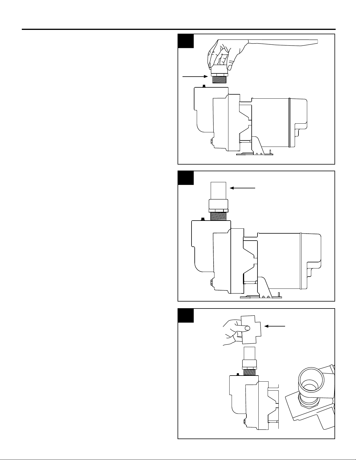
1. Thread 1-1/2 in. MPT x 1-1/2 in. slip adaptor
(not included) into the outlet port located at
the top of the pump.
2. Glue a 6 in. piece of 1-1/2 in. pipe (not
included) into the adaptor.
1
2
3. Glue a 1-1/2 in. tee (not included) to the pipe.
3
6
Page 7
PUMP PREPARATION FOR WELL AND SURFACE WATER
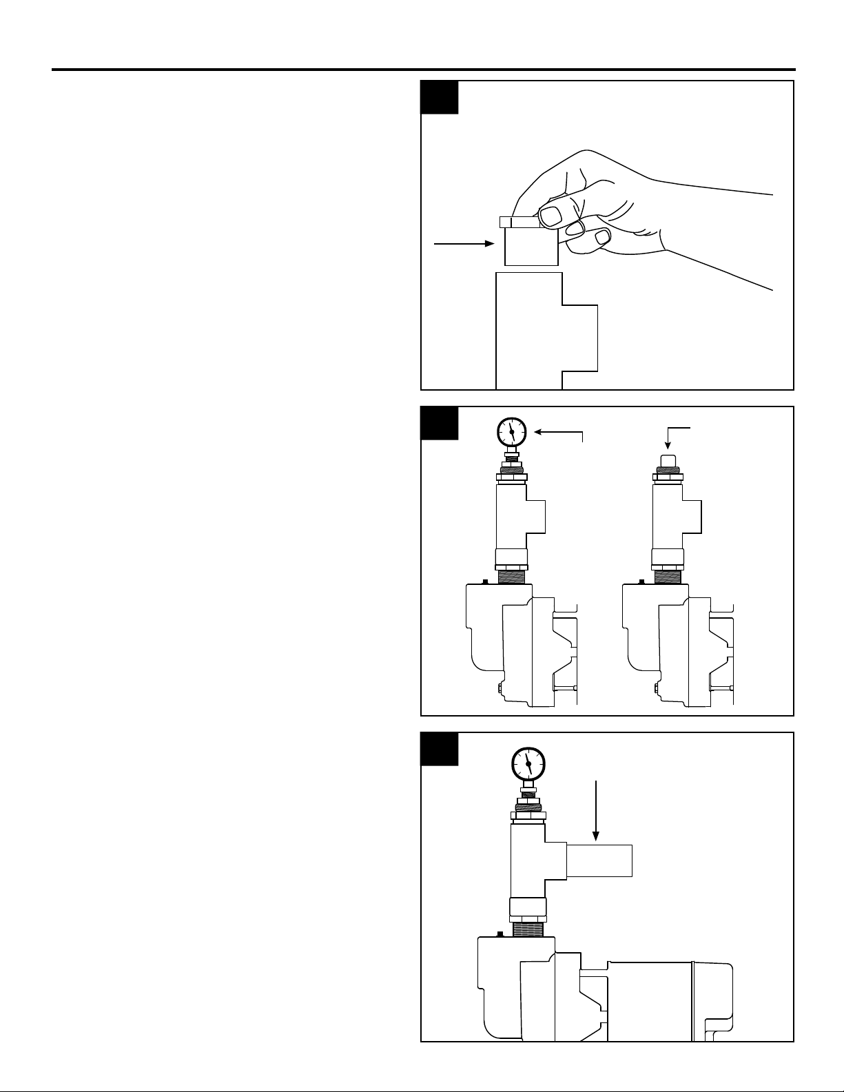
4. Glue a 1-1/2 in. slip x 1-1/4 in. adaptor (not
included) to the top opening of the 1-1/2 in.
tee.
5. Thread in a 1-1/4 in. priming plug or optional
priming plug with pressure gauge (neither
included).
NOTE: Hand tighten only, as this will be
removed for priming.
4
5
Priming Plug
with Pressure
Gauge
1-1/4 in.
Priming
Plug
6. Glue another 6 in. section of 1-1/2 in. pipe
(not included) into the opening in the
1-1/2 in. tee.
6
7
Page 8

PUMP PREPARATION FOR WELL AND SURFACE WATER
7. Glue the male thread side of a 1-1/2 in. union
(not included) to the pipe.
8. Thread 2 in. MPT x 2 in. slip adaptor (not
included) into the inlet port located on the
front of the pump body.
7
8
9. Glue an 8 in. section of 2 in. pipe (not
included) into the 2 in. adaptor.
9
8
Page 9

PUMP PREPARATION FOR WELL AND SURFACE WATER
10. Glue one side of a 2 in. union (not included)
to the pipe.
For Well Installations
11. Thread a 2 in. MPT x 2 in. slip adaptor (not
included) into the foot valve.
10
11
12. Glue 2 in. pipe (not included) into the
adaptor. Glue enough sections of pipe
together using 2 in. couplers (not included)
in order for the foot valve to be completely
submerged in water. Be sure inlet pipe
will remain fully submerged at the lowest
expected level of the water source.
12
9
Page 10

PUMP PREPARATION FOR WELL AND SURFACE WATER
13. Install well seal (not included) in order to
hold the inlet pipe in position in the well.
14. Glue a 90º elbow (not included) when the
inlet pipe is in line with the inlet port of the
pump.
13
14
Well Seal
Elbow
Inlet Pipe
Water Level
IL1261
Discharge to
Sprinkler System
For Surface Water Installations
For surface water installations, follow steps 11
and 12 above and then:
15. Glue a 45º elbow (not included) when the
inlet pipe is in line with the inlet port of the
pump.
15
Outlet Pipe
Elbow
Water
Level
Inlet
Pipe
Discharge to
Sprinkler System
10
Page 11

PUMP PREPARATION FOR WELL AND SURFACE WATER
Priming Plug
16. Support inlet pipe with pipe support (not
included).
16
PUMP INSTALLATION FOR WELL AND SURFACE WATER
1. Mount pump on a solid foundation as close
to the water source as possible.
1
CAUTION: Support the 2 in. inlet
pipe from the well or lake to the inlet port
to prevent sagging. Sagging will create air
Well Seal
pockets within the pipe that will prevent the
pump from priming and operating correctly.
Pipe
support
Water level
100 PSI
Pressure
Gauge
Union
Slope pipe upward
from water source
Use a concrete block or
other solid material to
support suction pipe
Union
Ball
Valve
Outlet
Pipe
2. Glue female 2 in. union (not included) to
the end of inlet pipe leading from the water
source.
2
Water
Level
Inlet
Pipe
Well
Water Level
2 in.
Female
Union
Discharge to
Sprinkler System
Outlet Pipe
Inlet
Pipe
11
Page 12

PUMP INSTALLATION FOR WELL AND SURFACE WATER
3. Connect the 2 in. union together to complete
the inlet line to the pump.
4. Glue a 6 in. piece of 1-1/2 in. pipe (not
included) to the female portion of the 1-1/2
in. union.
3
Water
Level
4
Outlet Pipe
2 in.
Union
Inlet
Pipe
1-1/2 in.
Union
5. Glue 1-1/2 in. ball valve (not included) to the
other end of the 6 in. piece of pipe.
12
5
Ball Valve
Page 13

PUMP INSTALLATION FOR WELL AND SURFACE WATER
6. Connect the 1-1/2 in. outlet pipe to the
sprinkler system (not included) by gluing in
additional sections of pipe (not included) as
needed.
7. Connect union to ensure proper t. Do not
tighten until after priming.
CAUTION: Do not glue union together.
6
Outlet Pipe
Inlet
Pipe
Discharge to
Sprinkler System
7
Outlet Pipe
Inlet
Pipe
Discharge to
Sprinkler System
13
Page 14

PUMP ELECTRICAL INSTRUCTIONS
WARNING
ELECTRICAL SHOCK ALERT.
Under-size wiring can cause motor failure and even fire. Use proper wire size specified in
the wire size chart on page 15.
ELECTRICAL SHOCK ALERT.
Replace damaged or worn wiring cord immediately.
ELECTRICAL SHOCK ALERT.
Do not kink power cable and never allow the cable to come in contact with oil, grease, hot surfaces,
or chemicals.
ELECTRICAL SHOCK ALERT.
The pump must be properly grounded using the proper wire cable with ground.
ELECTRICAL SHOCK ALERT.
Always disconnect pump from electricity before performing any work on the motor.
CAUTION
ELECTRICAL SHOCK MAY OCCUR
All wiring should be performed by a qualified electrician in accordance with the National Electric Code and local
electric codes.
ELECTRICAL SHOCK MAY OCCUR
Connect the pump to a separate electrical circuit with a dedicated circuit breaker. Reference the wire size chart
below for proper fuse size.
ELECTRICAL SHOCK MAY OCCUR
Protect the power cable from coming in contact with sharp objects.
PRODUCT DAMAGE MAY RESULT
Make certain that the power source matches the pump requirements. This pump has a dual voltage
motor and can run on 115 V or 230 V. This pump is wired from the factory to run on 230 volts; refer to
page 17 if you want to change the pump to run on 115 volts.
Wire Size Chart
Distance From
Motor To Fuse
Box, Meter or
Electrical Outlet
0-50 Ft.
50-100 Ft.
100-150 Ft.
150-200 Ft.
200-300 Ft.
Fuse Size (Amps)
(*) Not economical to run in 115 V; use 230 V
NOTE: This pump can be used with a variety of controls, including a pump start relay, pressure switch
with tank and indexing valve. See control manufacturer’s instructions for details.
115 Volt 230 Volt 115 Volt 230 Volt 115 Volt 230 Volt
Minimum Copper Wire Size Chart (Gauge)
Single Phase Motors
1 HP 1-1/2 HP 2 HP
12
8
*
*
*
20
14
14
12
12
10
15
14
12
10
8
*
*
20
14
14
12
12
10
15
12
10
8
*
*
20
14
14
12
10
10
15
Page 15

PUMP ELECTRICAL INSTRUCTIONS
1. Remove rear motor cover on pump by
unscrewing the two screws.
2. Thread electric wire strain relief (not
included) into wire opening on the side of the
motor of pump.
1
2
3. Insert wire through electric wire strain relief
and tighten screws.
3
L1
L1
A B
A B
L2
L2
15
Page 16

PUMP ELECTRICAL INSTRUCTIONS
4. Connect white power lead to L1 and black
power lead to L2.
4
5. Connect green ground wire to green
grounding screw. Re-install rear motor cover
to pump.
5
L1
L1
A B
A B
L2
L2
To change from 230 V to 115 V
6. The motor of pump is dual voltage and
can run on either 115 volts or 230 volts. In
general, 230 volts is more economical to run,
and requires a smaller wire size. The pump
is pre-set in the factory to run at 230 volts.
6
L2L1
A B
G R AY
RED
16
Page 17

PUMP ELECTRICAL INSTRUCTIONS
7. For 115 volts service, change the following
wires on the terminal board:
a. Using a pair of needle nose pliers,
pull the gray wire with the female flag
connector from the “B” terminal spade
post. Place it to the left on the “A”
terminal space post.
b. Pull the red wire with the female flag
connector from the “B” terminal. Place it
to the right on the L2 terminal space post.
7a
L2L1
A B
G R AY
RED
7b
c. Reinstall the rear motor cover.
L2L1
A B
G R AY
RED
7c
17
Page 18

PUMP PRIMING AND STARTUP
CAUTION: All pumps must be primed by
filling the pump cavity with water before they
are first operated. This may take several gallons
of water, as the entire inlet line will be filled in
addition to the pump cavity. The longer the inlet
line, the more water is required for priming.
1. Disconnect the 1-1/2 in. outlet union and
separate the pipe.
2. Remove the air relief plug on top of pump
and the 1-1/4 in. priming plug with pressure
gauge or plug. Refer to Pump Preparation
Step 5.
1
Outlet Pipe
Priming Plug
with Pressure
Gauge
Air Relief Plug
Inlet
Pipe
2
Priming Plug with
Pressure Gauge
3. Slowly fill pump cavity until water comes out
of air relief hole on top of the pump.
Air Relief Plug
3
Air Relief
Hole
18
Page 19

PUMP PRIMING AND STARTUP
4. Replace air relief plug and continue adding
water to pump cavity until water comes out of
the open outlet pipe at the open union.
5. Wait 10 minutes to see if water level drops
below the pipe tee. If level drops, check foot
valve. If level stays constant, replace the
priming plug.
4
Air Relief
Plug
5
Open Union
Outlet Pipe
Pipe Tee
Priming Plug with
Pressure Gauge
6. Reconnect 1-1/2 in. union on outlet pipe.
Open the ball valve (turn handle to line up
with pipe), and then turn on breaker to start
pump.
Water
Level
6
Pipe Tee
Closed
Open
19
Page 20

PUMP PRIMING AND STARTUP
IMPORTANT: If the pump fails to prime within five minutes:
7. Turn the power off at the break box. Check all pipe connections for leaks, making sure all
connections are water and air tight. Check the inlet pipe for any sagging, making sure the inlet pipe
is in a straight line to the pump. Watch for leaks or a milky color in the discharged water, which
indicated an air leak. Re-prime if necessary, following steps 1 through 6. Reset breaker at the
breaker box.
IMPORTANT: If the pump hums instead of pumping or turns off repeatedly, shut pump off
immediately. Check voltage. Pump is wired to run on 230 volts. If the pump cuts out or stops, you may
be attempting to connect to 115 volts. See PUMP ELECTRICAL INSTRUCTIONS Page 17 to see how
to correctly change the motor voltage to 115 volts.
SPECIFICATIONS
MOTOR DATA CHART - HSP SERIES
Locked
Rotor
Amps
62.0
31.0
72.0
36.0
108.0
54.0
HP Phase Volts
1
1-1/2
2
1
1
1
1
1
1
115
230
115
230
115
230
Code
Letter
H
G
G
Max
Amps
17.6
8.8
18.00
9.00
21.00
10.50
Model HP
HSP10P1
HSP15P1
HSP20P1
1
1-1/2
2
Suction
Lift (FT)
10
15
20
25
10
15
20
25
10
15
20
25
PERFORMANCE
Capacity - U.S. Gallons per Hour
Discharge Pressure (PSI)
15 20 25 30 35 40
3420
2820
2640
1440
4092
3780
3366
2520
4309
3894
3557
2640
3120
2640
2520
1380
3894
3660
3300
2490
4172
3780
3488
2599
2700
2220
2160
1320
3564
3420
2838
2430
4036
3600
3420
2531
2100
1800
1500
1020
3168
2970
2640
2280
3625
3300
3215
2430
1200
600
480
300
2508
2310
1848
1452
3078
2772
2531
2220
20
0
0
0
0
1716
1188
600
0
2462
2112
1573
720
Suction
Discharge
Pipe
2" 1-1/2"
2" 1-1/2"
2" 1-1/2"
Pipe
Page 21

TROUBLESHOOTING
Problem Possible Cause Corrective Action
A. Little or no
discharge
B. Pump will not
deliver water
or develop
pressure
C. Loss of
suction
D. Pump
vibrates and/
or makes
excessive
noise
E. Pump will not
start or run
F. Pump loses
prime.
1. Casing not initially filled with water 1. Fill pump casing
2. Vertical lift too high, or too long 2. Move pump closer to water source
3. Hole or air leak in inlet line 3. Repair or replace inlet line. Use thread
tape and pipe sealing compound
4. Foot valve too small 4. Match foot valve to piping or install one
size larger foot valve.
5. Foot valve or inlet line not
submerged deep enough in water
6. Motor wired incorrectly 6. Check wiring diagram
7. Inlet or outlet line valves closed 7. Open valves
1. No priming water in casing 1. Fill pump casing
2. Leak in inlet line 2. Repair or replace
3. Outlet line is closed and priming air
has nowhere to go
4. Inlet line (or valve) is closed 4. Open line or valve
5. Foot valve is leaking 5. Replace foot valve
6. Inlet screen clogged 6. Clean or replace inlet screen
1. Hole or air leak in inlet line 1. Repair or replace inlet line. Use thread
2. Vertical lift too high 2. Reduce vertical lift, install foot valve
3. Insufficient inlet pressure or suction
head
4. Clogged foot valve or strainer 4. Inspect foot valve and/or strainer for
1. Mounting plate or foundation not rigid
enough
2. Foreign material in pump 2. Disassemble pump and clean
3. Impeller damaged 3. Replace impeller
1. Motor wired incorrectly 1. Check wiring diagram
2. Blown fuse or open circuit breaker 2. Replace fuse or close circuit breaker
3. Loose or broken wiring 3. Tighten connections, replace broken
4. Stone or foreign object lodged in
impeller
5. Motor overheated 5. Allow unit to cool, restart after cooling
1. Clogged foot valve or strainer 1. Inspect foot valve and/or strainer for
2. Worn or broken foot valve 2. Inspect and replace
3. Hole or air leak in inlet line 3. Repair or replace inlet line. Use thread
5. Submerge foot valve lower in water
3. Open ball valve
tape and pipe sealing compound
and prime
3. Increase inlet pressure by adding
more water to tank or increasing back
pressure
debris, and remove
1. Reinforce plate or foundation
wiring
4. Disassemble pump and remove
foreign object
debris, and remove.
tape and pipe sealing compound
21
Page 22

CARE AND MAINTENANCE
Winterizing
CAUTION: Drain the entire system if there
is danger of freezing. A drain plug is provided at
the bottom of pump for this purpose. Remove
drain plug then loosen air relief plug.
REPLACEMENT PARTS LIST
To order parts, call 1-800-742-5044
1
Air Relief Plug
Drain Plug
G HE DCBA F
Motor
Assembly
HSP SERIES HP 1 1-1/2 2
ITEM
A
B
C
D
E
F
G Pump Body 023115 1 1 1
H* Hex Hd. Cap Screws 3/8 in. x 3/4 in. * 4 4 4
(*) Standard hardware item
NOTE: Motor assembly not available as a replacement part.
SINGLE PHASE MODEL NO.
DESCRIPTION PART NO.
Ring, Square Cut
Seal, Rotary and Ceramic (with Spring)
Impeller
Diffuser
Diffuser Insert
Rubber Diffuser
132429
131100
023211
132425
134240
132428
HSP10P1 HSP15P1 HSP20P1
1
1
021280
1
1
1
1
1
134138
1
1
1
1
1
134138
1
1
1
22
 Loading...