

Page 1
®
®
®
®
CONTACT
TOASTER
MODEL
HCTE13SW
Installation and
Operation
Instructions
2M-Z20691 Rev. A 9/21/2015
IL3020
Page 2
SAFETY SYMBOL
Using any part other than genuine Star factory supplied parts relieves the
manufacturer of all liability.
Star reserves the right to change specications and product design without
notice. Such revisions do not entitle the buyer to corresponding changes,
improvements, additions or replacements for previously purchased
equipment.
Due to periodic changes in designs, methods, procedures, policies and
regulations, the specications contained in this sheet are subject to change
without notice. While Star International Holdings Inc., Company exercises
good faith efforts to provide information that is accurate, we are not
responsible for errors or omissions in information provided or conclusions
reached as a result of using the specications. By using the information
provided, the user assumes all risks in connection with such use.
These symbols are intended to alert the user to the presence of
important operating and maintenance instructions in the manual
accompanying the appliance.
RETAIN THIS MANUAL FOR FUTURE REFERENCE
NOTICE
MAINTENANCE AND REPAIRS
Contact your local authorized service agent for service or required maintenance.
Please record the model number, serial number, voltage and purchase date in the area below and have it
ready when you call to ensure a faster service.
Authorized Service Agent Listing
Model No.
Serial No.
Voltage
Purchase Date
Reference the listing provided with the unit
or
for an updated listing go to:
Website: www.star-mfg.com
E-mail customerservice@star-mfg.com
Service Help Desk
Business 8:00 am to 4:30 p.m. Central Standard Time
Hours:
Telephone: (314) 678-6303
Fax: (314) 781-2714
E-mail customerservice@star-mfg.com
Website: www.star-mfg.com
Mailing Address: Star International Holdings Inc., Company
10 Sunnen Drive
St. Louis, MO 63143
U.S.A
2M-Z20691; Ultra-Max Contact Toaster
2
Page 3
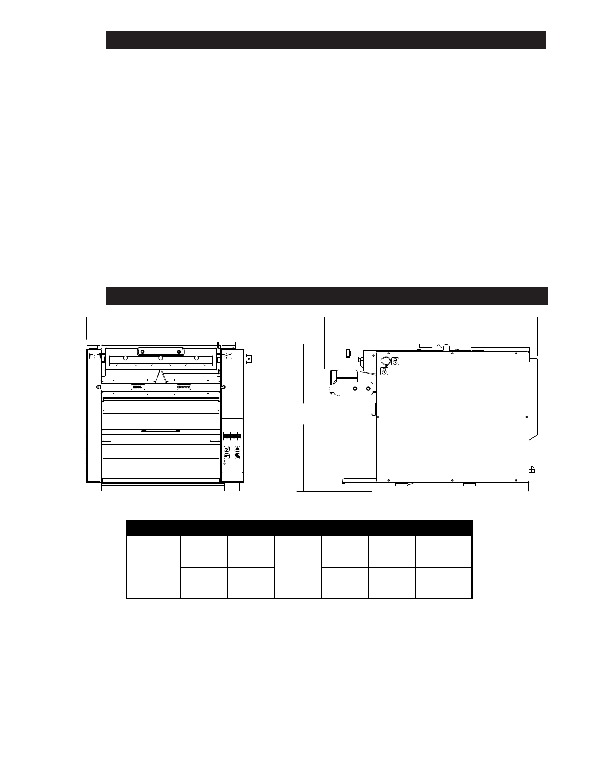
TABLE OF CONTENTS
Specications . . . . . . . . . . . . . . . . . . . . . . . . . . . . . . . . . . . . 1
Features & Benets . . . . . . . . . . . . . . . . . . . . . . . . . . . . . . . . . 2
General Information . . . . . . . . . . . . . . . . . . . . . . . . . . . . . . . . . 3
Uncrating & Inspecting . . . . . . . . . . . . . . . . . . . . . . . . . . . . . . . 3
Electrical Connection . . . . . . . . . . . . . . . . . . . . . . . . . . . . . . . . 3
Assembly & Inspection . . . . . . . . . . . . . . . . . . . . . . . . . . . . . . . 4
Toaster Settings . . . . . . . . . . . . . . . . . . . . . . . . . . . . . . . . . . . 4
Daily Operation . . . . . . . . . . . . . . . . . . . . . . . . . . . . . . . . . . . 5 & 6
Cleaning . . . . . . . . . . . . . . . . . . . . . . . . . . . . . . . . . . . . . . . 7
Troubleshooting . . . . . . . . . . . . . . . . . . . . . . . . . . . . . . . . . . . 8
Maintenance . . . . . . . . . . . . . . . . . . . . . . . . . . . . . . . . . . . . 9-10
Warranty . . . . . . . . . . . . . . . . . . . . . . . . . . . . . . . . . . . . . . .11
Wiring Diagram . . . . . . . . . . . . . . . . . . . . . . . . . . . . . . . . . . . . 12
Exploded View . . . . . . . . . . . . . . . . . . . . . . . . . . . . . . . . . . . 14-17
SPECIFICATIONS
2M-Z20691; Ultra-Max Contact Toaster
19.25”
24.662”
13.7”
Electrical Specications
Model Voltage Hz Ph Amps Watts Powercord
HCTE13SW
208V 60
230V 50 10.5 2450 CEE7/VII
1
12.25 2550 6-20P
240V 60 11 2650 6-20P
IL3019
1
Page 4
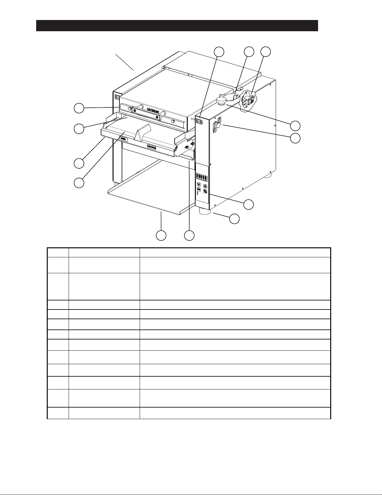
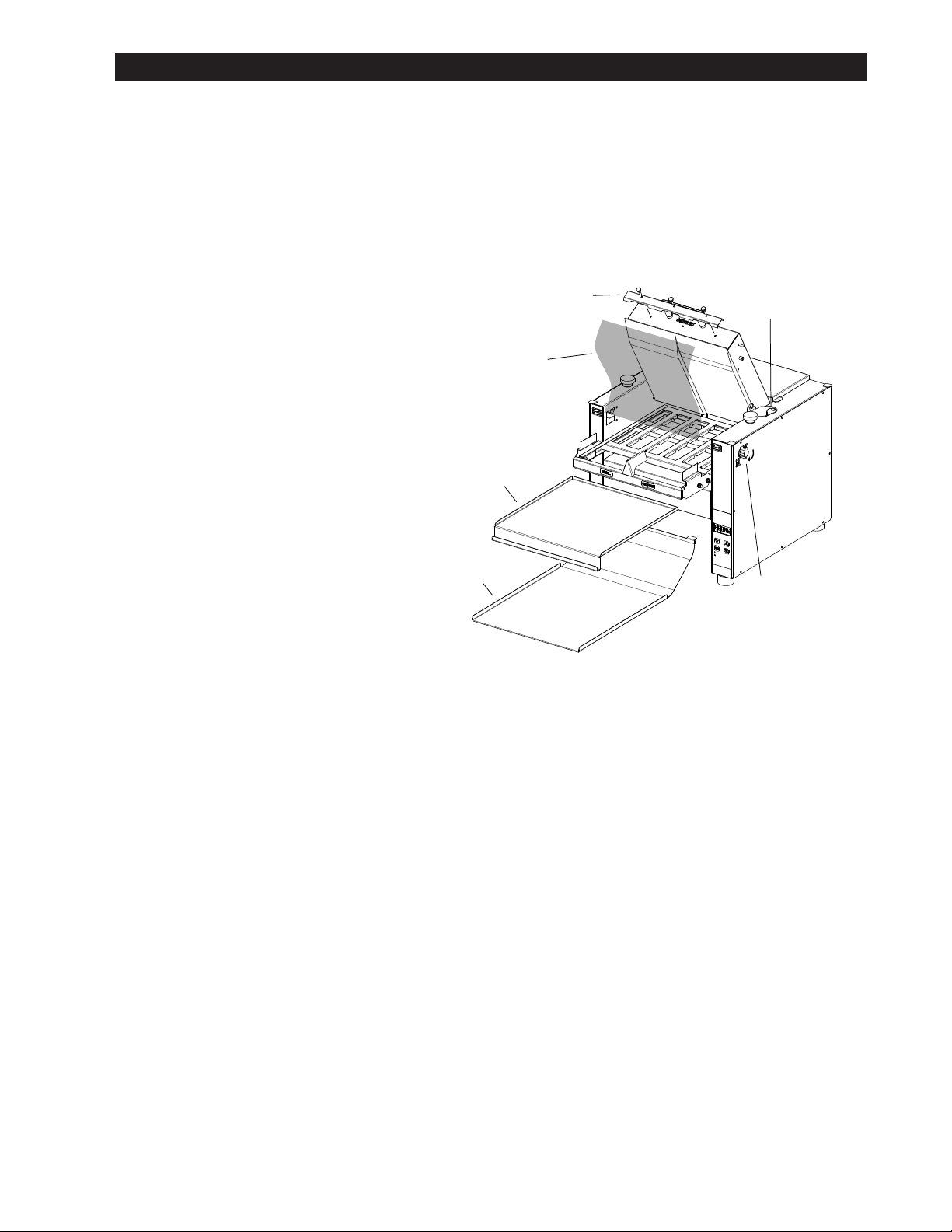
FEATURES & BENEFITS
M
L
K
J
Namplate
A
B C
D
E
IL3021
F
G
HI
A Platen Height Indicator Indicates the height of the upper platen
B Platen Support Bracket Keeps the upper platen in the up position, useful while cleaning
Interrupts the heater tube connections if the air temperature in the control box
C High Limit
D Platen Height Knob Controls the height of the upper platen
E Locking Platen Latch Keeps the upper platen in the down position.
F Control Board Controls the conveyor speeds, turns unit on & off, & temperature settings.
G Foot Silicone foot keeps unit rmly in place.
H Crumb Tray Slide out crumb tray used to catch particles from falling
I Toaster Chute Removable Chute returns product for easy access.
J Conveyor Takes the heel and crown separately through their toasting process
K Burn Guard Protects users from touching the conveyor belt
Durable Non-Stick Coated
L
Sheet
M Upper Platen Assy Heating surface designed to toast the product as it slides across the surface
exceeds 190°F (88°C). This limit switch can be reset manually by pushing the
button in the center of the switch.
Non-Stick surface between the upper platen and the product, allowing the product
to slide easily through the toasting process.
2M-Z20691; Ultra-Max Contact Toaster
2
Page 5
CAUTION
GENERAL INFORMATION
This equipment is designed and sold for commercial use only by personnel trained and
experienced in its operation and is not sold for consumer use in and around the home nor
for use directly by the general public in food service locations.
Before using your new equipment, read and understand all the instructions & labels
associated with the unit prior to putting it into operation. Make sure all people associated
with its use understand the units operation & safety before they use the unit.
INSPECTION
UN-CRATING AND INSPECTING
Unpack the unit and components from the shipping container. Remove all visible packing
material and those from inside the cooking chamber. If damage is discovered, le a claim
immediately with the carrier that handled the shipment. Do not operate the unit if it was
damaged during shipping. All shipping containers should be checked for freight damage
both visible and concealed. This unit has been tested and carefully packaged to insure
delivery of your unit in perfect condition. If equipment is received in damaged condition,
either apparent or concealed, a claim must be made with the delivering carrier.
Concealed damage or loss - if damage or loss is not apparent until after equipment is
unpacked, a request for inspection of concealed damage must be made with carrier within
15 days. Be certain to retain all contents plus external and internal packaging materials for
inspection. The carrier will make an inspection and will supply necessary claim forms.
2M-Z20691; Ultra-Max Contact Toaster
ELECTRICAL CONNECTION
Disconnect the unit from the power source before installing or removing any parts.
Be absolutely sure that the ground connection for the receptacle is properly wired.
Do not connect equipment to power without proper ground connections. Improper
grounding may result in personal injury or death.
CAUTION
Allow enough space around the toaster for adequate ventilation. Do not operate the unit
without the crumb tray properly positioned. Overheating and poor toasting may occur.
Read all labels on the unit and follow their instructions.
WARNING
Before making any electrical connection to this unit, check that the power
supply is adequate for the voltage, amperage and requirements stated on the
rating plate. A wiring diagram is included.
WARNING
DO NOT CUT OR REMOVE THIS PLUG OR THE GROUNDING PRONG FROM
THE PLUG. FAILURE TO COMPLY MAY RESULT IN DEATH OR SERIOUS
INJURY.
WARNING
CONNECT/PLUG UNIT INTO DEDICATED A. C. LINE ONLY SPECIFIED ON THE
DATA PLATE OF THE UNIT.
CAUTION
SOME SURFACES ARE EXTREMELY HOT DURING OPERATION AND CARE SHOULD
BE TAKEN WHILE USING THIS UNIT.
3
Page 6
ASSEMBLY AND INSTALLATION
The unit was shipped fully assembled and ready to plug into a standard outlet specied for its
voltage and amp draw. If improper electrical supply is determined, contact a qualied electrician
prior to using the unit. Removal and replacement of the power cord and plug voids the warranty.
For assistance, contact your local authorized service agent for service or required maintenance.
1. Place the unit in its operating location.
2. Wipe down the exterior with a damp cloth.
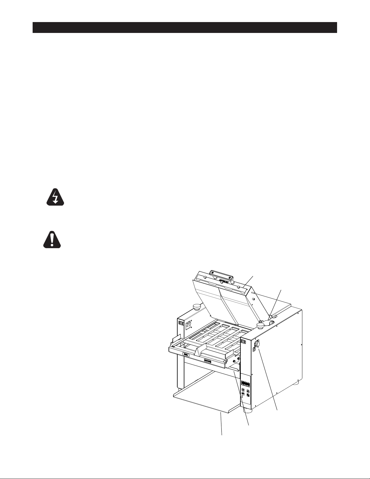
3. Place the Toaster Chute & Crumb Tray into position.
4. Unlock the Platen Latch and raise the platen, move the Platen Support Bracket to hold the
platen in the up position.
Sheet Retainer
5. Loosen the Sheet Retainer and
install the non-stick sheet into
position, and secure.
Non-Stick Sheet
6. Lower the Platen and latch in
place.
CAUTION
Failure to use non-stick sheets can
lead to damaging the unit and a loss
of warranty. The durable non-stick
coated sheets are not a warranty
item.
TOASTER SETTINGS
Before using the unit for the rst time,
test the pass time of the conveyor
belt.
The pass time through the toaster
should be between 16 to 20 seconds for standard setting.
Crumb Tray
Toaster Chute
Platen Support
Bracket
IL2848a
Platen Latch
1. Turn unit ON and wait for it to complete the PRE-HEAT process.
2. Set the Platen height by adjusting the two (2) Platen Height Knobs on top of the unit.
3. Make sure the platen lock is on.
4. Place a bun on the conveyor belt, cut side up, “HEEL” on one side and
“CROWN” on the other.
IF TO DARK: Decrease TEMP.
IF TO LIGHT: Increase TEMP. or lower platen
2M-Z20691; Ultra-Max Contact Toaster
4
Page 7
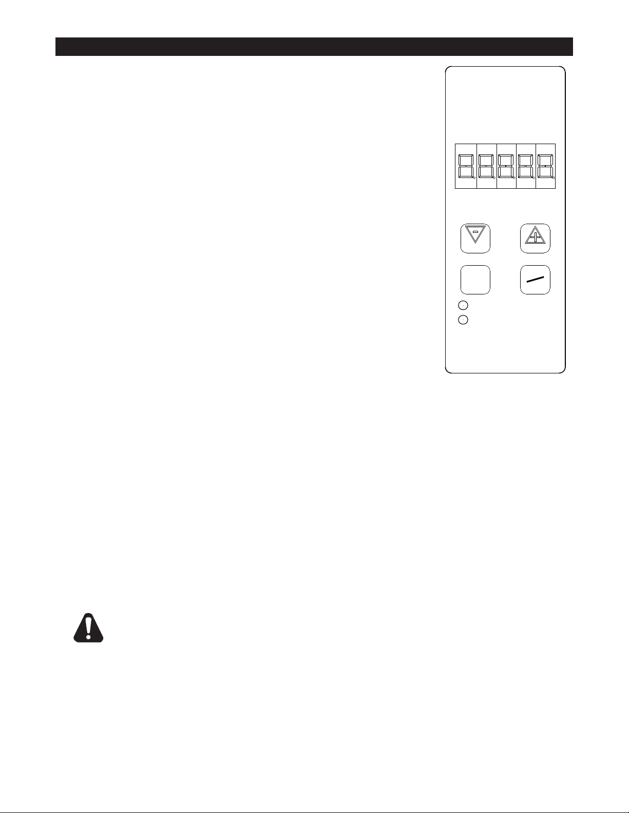
DAILY OPERATION ELECTONIC CONTROL
IL2856
RUN
CLEAN
SET
TEMP
ON
OFF
CHANGING TEMPERATURE
1. Push and hold the "SET TEMP" button for three seconds.
2. The display will ash the current top temperature setting.
3. Using the ↑ and ↓ adjust the top heat to desired temperature
(increments of 10°)
4. Press the "SET TEMP" button again to change the bottom heat
setting.
5. Using the ↑ and ↓ adjust the bottom heating setting (0 – 10).
6. Press the "SET TEMP" button again to save the settings and exit
program mode.
CHANGING CONVEYOR SPEED
1. Push and hold the ↑ and ↓ for three seconds
2. Using the ↑ and ↓ adjust the motor speed to the desired
setting (1 through 99)
3. Press the "SET TEMP" button to exit the program
CHECK TEMPERATURE SETTING
1. Press the "SET TEMP" button to check the platen temperature.
CLEAN MODE
1. Press the "CLEAN" button to enter the clean mode
a. Elements will be turned OFF and the belt will continue to run
b. The screen will ash CLEAN and WAIT.
c. When the platen has lowered to a safe temperature the screen will ash CLEAN and
READY.
2. Press the "ON/OFF" button to exit the clean mode.
CHANGING BUN THICKNESS SETTING
1. Set the "Height Adjustment Knobs" to their desired settings.
2. Turn unit ON, allow to warm-up before proceeding.
3. Place buns on the conveyor, cut side up.
4. Toasted buns will drop down the toaster chute.
5. Turn the "Height Adjustment Knobs" to lower the platen for darker buns, raise for lighter buns.
2M-Z20691; Ultra-Max Contact Toaster
CERTAIN SURFACES ARE EXTREMELY HOT DURING OPERATION AND
CARE SHOULD BE TAKEN WHILE USING THIS UNIT.
CAUTION
5
Page 8
CLEANING
Preventive maintenance for your Ultra-Max Contact Toaster consists of the following recommended
cleaning procedures. To keep your toaster in top operating condition, these steps should be performed
daily or weekly as indicated.
Daily Cleaning
1. Turn the temperature knob to the "OFF" position, and keep the power switch in the "ON" position.
IMPORTANT: Allow the unit to cool before attempting to clean it.
2. Wipe down moving belt with mild detergent and damp cloth.
(an abrasive pad can be used on metal belt).
3. Wipe down exterior of toaster with mild detergent and damp cloth.
4. Remove non-stick sheet and clean with mild detergent and damp cloth. (If excess buildup is unable
to be removed and causing buns to stick to the sheet, a new sheet may need to be installed.)
5. Remove crumb tray and toast slide and wash in a sink with mild detergent.
6. Dry and return crumb tray, toast slide, and non-stick sheet back into position.
7. Turn the power switch to the "OFF" position, until you need
DO NOT IMMERSE OR LET THE UNIT STAND IN WATER.
DO NOT HOSE DOWN THE UNIT OR THE TABLE/COUNTER IF THE
WARNING
UNIT IS ON THE TABLE/COUNTER.
KEEP AWAY FROM RUNNING WATER.
CAUTION
DO NOT use caustic cleaners on any surface of the unit, conveyor belt or
Durable Non-Stick Coated Sheets
Sheet Retainer
Platen Suppot Bracket
2M-Z20691; Ultra-Max Contact Toaster
IL2859b
Locking Platen Latch
Crumb Tray
Toaster Chute
6
Page 9
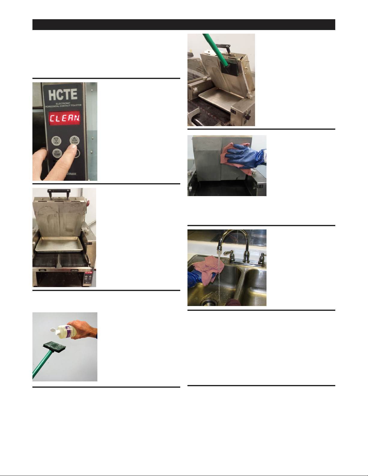
CLEANING: Upper Platen
Supplies
Kay No-Scratch Pad and Holder
Quarter Sheet Pan 9 1/2" x 13" x 1"
Heat Resistant Gloves
Clean, Sanitized-Soaked Cloth
• Press and hold CLEAN
for 3 seconds to enter
clean mode.
• Display will ash CLEAN
WAIT until platen reaches
cleaning temperature,
approximately 275°F.
• Wait for display to
show CLEAN READY,
approximately 15 minutes.
• Prop open platen, remove
non-stick sheet, and
place quarter sheet under
platen on belt to contain
drippings.
NOTE: If quarter sheet is
unavailable rags can be
used to contain drippings.
WARNING: Wear heat resistant gloves to clean
toaster. Attach grill cleaning pad to holder.
• Use the pad to scrub
one side of the platen
NOTE: Add another
portion of Heat-Activated
Cleaner to the pad
before cleaning the other
side of the platen.
• Using a clean,
sanitizer-soaked
cloth from a bucket
of sanitizer solution,
wipe the platen
to remove HeatActivated Cleaner.
NOTE: Use damp cloth only as too much water
will damage the toaster.
• Rinse the cloth in the
RINSE sink before
dipping into the bucket
of Sanitizer Solution,
regularly throughout
the cleaning process.
Do not contaminate
the sanitizer Solution
with Heat-Activated
Cleaner.
2M-Z20691; Ultra-Max Contact Toaster
• Portion Heat-Activated
Grill and Toaster
Cleaner (1 oz.) onto
cleaning pad and never
onto toaster platen.
• Remove drip pan and wipe down belt with sanitizer
soaked cloth.
• Turn unit ON and wipe the rest of the belt as it
turns with sanitizer soaked cloth.
• Turn the unit OFF and wipe down external surfaces
of the unit.
NOTE: Use damp cloth only as too much liquid
will damage the toaster.
• Remove crumb tray and toast slide and clean in
sink with soap and water.
• Clean non-stick sheet with soap and water.
• Dry and return all pieces to their original positions.
• Close and latch platen
NOTE: Operation of unit without non-stick sheet
installed will damage the unit.
7
Page 10

TROUBLESHOOTING GUIDE
A. Unit Will Not Heat, Conveyor Belt Will Not Move.
1) Be sure the main circuit breaker is switched to the ON
2) Check to see if the toaster is plugged in and all controls are turned to the ON position.
B. Unit Has Heat Only On One Side, Conveyor Belt Turns Freely.
1) Contact your local service agent,, as heating element may need replacing.
C. Conveyor Will Not Turn, Unit Heats Properly.
To check for mechanical binding:
1) DISCONNECT UNIT FROM POWER SOURCE.
2) Remove 4 screws on the back of the toaster and remove back panel.
3) Remove the right side panel.
4) Loosen the four screws that hold the drive motor in place.
5) Slide the motor up allowing the drive chain to be removed from the sprockets.
6) Move the conveyor belt by hand to check for mechanical binding. If conveyor moves freely,
contact your local service agent,, as the drive motor and/or speed control
may need replacing.
7) Re-install the rear and side panels.
D. Heat Limit Switch (Reset)
Your Ultra-Max contact toaster is equipped with an automatically activated heat limit switch
that interrupts the heater tube connections if the ambient temperature in the control box
exceeds 190°F (88°C). This switch can be reset manually by pushing the red button located
behind the right side panel as shown in the Components Illustration on Page 2.
1) DISCONNECT UNIT FROM POWER SOURCE.
2) Check to see if air intake area in the bottom center of the control box cover is free of dust,
grease or other obstructions.
3) Check if crumb tray is in place. .
4) If no obstructions to the airow can be found
contact your local service agent, for assistance.
E. Conveyor Turns At One Speed Regardless Of Speed Control Setting
(HCTE models only).
1) Contact your local service agent,, as speed control should be replaced.
F. Product Sticking To Conveyor Or Slide
Your Ultra-Max Contact Toaster is designed to toast product that is current room temperature.
DO NOT attempt to put frozen, refrigerated material in the toaster.
Doing so may cause it to come out doughy or very moist, as well as possibly sticking to parts of the
unit. Follow the cleaning procedures.
2M-Z20691; Ultra-Max Contact Toaster
8
Page 11

MAINTENANCE PROCEDURES
A. Replacing the Bottom Element
1) DISCONNECT UNIT FROM POWER SOURCE.
2) Remove the side panels and bottom panel.
3) Remove element wire from terminal block connection, keeping top and
bottom wires separate.
4) Lift element retainers by loosening retaining screws and removing the retainer plate up.
5) Gently, pull defective element out of unit.
6) Gently, put new element into unit.
7) Slide the retainer back into place. Tighten the screw to secure the retainer in place
over the ends of the elements.
B. Replacing the Fan Motor
1) DISCONNECT UNIT FROM POWER SOURCE.
2) Remove the toaster slide.
3) Remove screws from the bottom panel.
4) Unplug power supply cord from fan motor.
5) Remove (4) screws, which hold fan motor and grill to bottom of unit and remove fan.
6) Put replacement motor and grill in place and secure to the bottom of unit with screws.
7) Reconnect power supply cord to fan motor.
8) Replace bottom panel. Fasten with screws removed in step 2.
C. Replacing the Belt Drive Motor
1) DISCONNECT UNIT FROM POWER SOURCE.
2) Remove the right side and bottom panels.
3) Remove sprocket from motor shaft, using an Allen wrench and loosening the set-screw.
4) Remove the wire from terminal block connecting the drive motor to internal wiring.
On units rated 208 or 240 volts, note which color leads are being used for these connections
and which lead is capped with white tape. The new motor should use the same arrangement.
5) Remove screws holding motor in place and remove motor from unit.
6) Put new motor in place and attach loosely with mounting screws.
7) Replace sprocket on motor shaft.
NOTE The two sprockets should line up parallel with each other, so the chain does not twist
any during operation. Also the hub gets installed closets to the motor.
8) Slide motor until the drive chain has about 1/4” slack when lightly pushed at the center of its top
open run. See chain tensioning illustration.
9) Tighten screws to secure motor.
10) Rewire leads same as removed in step 4.
11) Replace previously removed panels.
2M-Z20691; Ultra-Max Contact Toaster
D. Clean the Air Intake (Once A Week)
1) DISCONNECT UNIT FROM POWER SOURCE.
2) Place unit on its backside.
3) Use a vacuum cleaner and or a damp cloth to clean
the air intake.
E. Lubricate the Chain & Sprockets (Every 6 Months)
1) DISCONNECT UNIT FROM POWER SOURCE.
2) Remove enclosure exposing chain drive.
3) While wearing rubber gloves and using an extreme pressure,
synthetic chain lubricant with a temperature range up to
400°F (204°C) lubricate chain and sprockets. Apply liberally.
This grease is available as part no. 1L-Z12397.
4) Replace enclosure, Reconnect power source and test unit.
9
1/4”
Chain Tension
Page 12

MAINTENANCE continued
REMOVING & REPLACING SILICONE BELT
1. Disconnect unit from power allow to cool before beginning process.
2. Remove guard from in front of the belt.
3. Rotate belt by hand until belt seam is visible.
4. The Idler Shaft is spring loaded. Press on the front idler shaft to remove tension from the
belt. (Continuous pressure is required).
5. Pull splicing rod from belt.
6. Carefully release pressure from idler shaft so the roller is not propelled from the unit by the
springs.
7. Installation is similar to removal. Feed the belt around the drive shaft and idler shaft rollers
making sure the tracking guide on the backside of the belt is seated in the roller grooves.
8. Press the front roller to create slack in the belt.
9. Feed the splicing rod through the two ends of the belt.
10. Remove pressure from roller and install belt guard.
11. Plug unit back into outlet and test for proper operation.
Top Panel
Burn Guard
CAUTION
Groove
Idler Shaft
Locking Platen Latch
Platen Support Bracket
Above: Removing and Installing Silicone Belt
Drive Shaft
Groove
IL2857
DISCONNECT THE POWER SUPPLY BEFORE SERVICING OR
CLEANING THIS OVEN. SAFEGUARD THE POWER SO IT CANNOT BE
ACCIDENTALLY RESTORED. FAILURE TO DO SO COULD RESULT IN
DISMEMBERMENT, ELECTROCUTION, OR FATAL INJURY.
2M-Z20691; Ultra-Max Contact Toaster
10
Page 13

Visit our Website at: www.star-mfg.com Email: customerservice@star-mfg.com
This unit has been tested for proper operation before leaving our plant to insure delivery of your unit in perfect condition. However, there are instances in which
the unit may be damaged in transit. In the event you discover any type of damage to your product upon receipt, you must immediately contact the transportation
company who delivered the item to you and initiate your claim with same. If this procedure is not followed, it may affect the warranty status of the unit.
All workmanship and material in Star products have a one (1) year limited warranty on parts & labor in the United States and Canada. Such warranty is limited
to the original purchaser only and shall be effective from the date the equipment is placed in service. Star's obligation under this warranty is limited to the repair
of defects without charge, by the factory authorized service agency or one of its sub-agencies. Models that are considered portable (see below) should be taken
to the closest Star service agency, transportation prepaid.
THOROUGHLY INSPECT YOUR UNIT ON ARRIVAL
LIMITED EQUIPMENT WARRANTY
> Star will not assume any responsibility for loss of revenue.
> On all shipments outside the United States and Canada, see International Warranty.
* The warranty period for the Ultra-Max, Hot Plates, Griddles, Charbroilers is (3) years parts & labor.
* The warranty period for the Star-Max, Charbroilers, Griddles, Hot Plates, Fryers & Finishing Oven is (2) years parts & labor.
* The warranty period for the JetStar six (6) ounce & Super JetStar eight (8) ounce series popcorn machines is two (2) years.
* ThewarrantyperiodfortheChrome-MaxGriddlesisve(5)yearsonthegriddlesurface.Seedetailedwarrantyprovidedwithunit.
* The warranty period for Dura-Tec coatings is one year under normal use and reasonable care. This warranty does not apply if damage occurs to
Dura-Teccoatingsfromimpropercleaning,maintenance,useofmetallicutensils,orabrasivecleaners,abrasivepads,productidentiersand
point-of-sale attachments, or any other non-food object tha comes in continuous contact with the roller coating. This warranty does not apply to the
“non-stick” properties of such materials.
> This warranty does not apply to "Special Products" but to regular catalog items only. Star's warranty on "Special Products" is six (6) months on parts
and ninety (90) days on labor.
> This warranty does not apply to any item that is disassembled or tampered with for any purpose other than repair by a Star Authorized Service Center or
the Service Center's sub-agency.
> This warranty does not apply if damage occurs from improper installation, misuse, wrong voltage, wrong gas or operated contrary to the Installation and
Operating instructions.
> This warranty is not valid on Conveyor Ovens unless a "start-up/check-out" has been performed by a Factory Authorized Technician.
Parts that are sold to repair out of warranty equipment are warranted for ninety (90) days. The part only is warranted, the labor to replace the part is NOT warranted.
1. Traveltimeandmileagerenderedbeyondthe50mileradiuslimit
2. Mileage and travel time on portable equipment (see below)
3. Labor to replace such items that can be replaced easily during a daily cleaning
routine, ie; removable kettles on fryers, knobs, grease drawers on griddles, etc.
4. Installation of equipment
5. Damagesduetoimproperinstallation
6. Damages from abuse or misuse
7. Operated contrary to the Operating and Installation Instructions
8. Cleaning of equipment
9. Seasoning of griddle plates
Star will not honor service bills that include travel time and mileage charges for servicing any products considered "Portable" including items listed below.
These products should be taken to the Service Agency for repair:
* TheModel510FD,510FFFryer.
* TheModel526TOAToasterOven.
* TheModelJ4R,4oz.PopcornMachine.
*TheModel518CMA&526CMACheeseMelter.
* TheModel12MC&15MC&18MCPHotFoodMerchandisers.
* TheModel12NCPW&15NCPWNachoChip/PopcornWarmer.
* All Hot Dog Equipment except Roller Grills & Drawer Bun Warmers.
2M-Z20691; Ultra-Max Contact Toaster
* All Nacho Cheese Warmers except Model 11WLA Series Nacho Cheese Warmer.
* All Condiment Dispensers except the Model HPD & SPD Series Dispenser.
* All Specialty Food Warmers except Model 130R, 11RW Series, and 11WSA Series.
* AllQCS/RCSSeriesToastersexcept Model QCS3 & RCS3 Series.
* All Fast Steamer Models except Direct Connect Series.
The foregoing warranty is in lieu of any and all other warranties expressed or implied and constitutes the entire warranty.
Should you need any assistance regarding the Operation or Maintenance of any Star equipment; write, phone, fax or email our Service Department.
In all correspondence mention the Model number and the Serial number of your unit, and the voltage or type of gas you are using.
SERVICES NOT COVERED BY WARRANTY
PARTS WARRANTY
10. Voltage conversions
11. Gas conversions
12. Pilot light adjustment
13. Miscellaneous adjustments
14. Thermostat calibration and by-pass adjustment
15. Resettingofcircuitbreakersorsafetycontrolsorresetbuttons
16. Replacementofbulbs
17. Replacementoffuses
18. Repairofdamagecreatedduringtransit,delivery,&
PORTABLE EQUIPMENT
FOR ASSISTANCE
installationORcreatedbyactsofGod
ALL:
* Pop-Up Toasters
* Butter Dispensers
* Pretzel Merchandisers
(Model 16PD-A Only)
* Pastry Display Cabinets
* Nacho Chip Merchandisers
* Accessories of any kind
* Sneeze Guards
* Pizza Ovens
(Model PO12 Only)
* Heat Lamps
* Pumps-Manual
11
2M-4497-2 11/21/14
Page 14

FAN
CONVEYOR
MOTOR
TOP ELEMENT
BOTTOM ELEMENT
HI-TEMP
SWITCH
HB1
HT1
L1
F1
M1
L2
OT2
M2
F2
OT1
HB2 HT2
THIS DRAWING CONTAINS INFORMATION CONFIDENTIAL TO STAR MFG. INT'L. INC.
NO REPRODUCTION OR DISCLOSURE OF ITS CONTENTS IS PERMITTED.
DATE
TOLERANCES UNLESS OTHERWISE NOTED
FRACTIONS ±1/64 DECIMALS ±.015 ANGLES ±1°
STAR MANUFACTURING INTERNATIONAL INC.
#10 SUNNEN DRIVE, ST. LOUIS, MO. 63143, USA
CK.
MATERIAL
FINISH
PART NO.
DESCRIPTION OF CHANGE
REVISIONS
MODEL NO.
TITLE
DATE
LTR
DR
DR.
-
-
-
-
-
MH
SK-2799
HCTE
WIRING DIAGRAM, SINGLE BOTTOM
-
-
MRC
7/11/14
120V
240V
240V
120V
120V
12
2M-Z20691; Ultra-Max Contact Toaster
Page 15

2M-Z20691; Ultra-Max Contact Toaster
13
Page 16

1
2
38 62
23
53
63
7
8
9
58596061
64
5
6
10
66 67
24
23
65
57
56
55
54
18
19
13
11
12
14
3
15
16
4
17
31
20
30
21
22
23
24
25
52
51
47
46
49
5023
Model: HCTE13SW Contact Toasters
w/electronic controls
48
4445
14
43
42
40
41
23
29
32
39
27
28
SK2914 Rev. - 7/13/15
26
33
34
37
36
35
2M-Z20691; Ultra-Max Contact Toaster
38
®
Page 17

2M-Z20691; Ultra-Max Contact Toaster
PARTS LIST September 21, 2015, Rev. A
Model: HCTE13SW Contact Toaster
Fig No Part No Quantity Description Application
1 HC-CT0005 1 PLATEN COVER ASY
2 2K-Z17714 2 BUSHING, OUTER
3 2C-6517 6 NUT 1/4-20 HEX STL NP
4 2A-Z17716 2 SUPPORT, 1/4-20 X 11/32
5 2A-Z17727 2 SPACER, 5/8”OD X 0.266”ID
6 2R-Y2830 1 HANDLE HARRY DAVIES 4560
7 2C-Z18503 2 SCREW, SOCKET CAP 1/4-2O
8 HC-Z17713 1 RETAINER, PTFE SHEET
9 2A-Z17712 3 THUMBSCREW 8-32 X .375
10 HC-Z17724 1 THERMOPROBE BRKT
11 HC-Z17711 1 ELEMENT COVER
12
13 2F-Z17708 1 13” TOP CASTING
14 2A-Z18504 1 SPACER, 3/8IN X 1/4IN
15 2C-Y7595 1 BOLT 1/4-20X1/2 THS STL
16 2H-Z18588 7 TEFLON SHEET, 0.003 TK
17 HC-CT0006 1 BACK PANEL ASY
18 2C-Z10075 1 SCREW-1/4-20X3/8 SS THS
19 HC-Z17737 1 PLATEN SUPPORT BRKT
20 2E-200566 1 SWTCH,RSET,0796-190F TRPS
21 2A-CT0015SB 1 BELT DRIVE SHAFT ASSEMBLY
22 HA-112261 2 BEARING ASSY PTFE/BRONZE
23 2C-Z6929 34 NUT, 10-24 KEPS SS
24 2P-200646 1 SPROCKET, 25B20 X 5/16
25 2P-150013 1 DRIVE CHAIN #25 ROLLER
26 2P-200648 1 SPROCKET, 25B32 X 5/16
27 2E-Z17514 1 SENSOR, SPEED
28 HC-CT0008 1 SPEED CONTROL BRKT ASY
29 2U-Z9657 1 MOTOR,11RPM-CW,NEW STYLE
30 2K-Y3240 1 BUSHING HEYCO SR 17-2
31 2E-Z14254 1 TERMINAL BLOCK 6-POLE
32 HC-CT0013 1 RIGHT ADJUSTMENT BRKT ASY
33 HC-CT0014 1 PLATEN LATCH ASY
34 2M-Z18513 1 LABEL, UNLOCK SYMBOL
35 2M-Z18512 1 LABEL, LOCK SYMBOL
36 2R-Z17729 1 KNOB, 1-1/4 X 5/8 X 1/2
2N-Z17710
1
2N-Z17749 ELEMENT, METAL 2300W 208V 208V
ELEMENT, METAL 2300W 240V 240V, 230V
15
Page 18

PARTS LIST September 21, 2015, Rev. A
Model: HCTE13SW Contact Toaster
Fig No Part No Quantity Description Application
37 HC-Z17742 1 PANEL, RIGHT COVER
38 2C-6349 24 SCREW #8X3/8 B THP STL NP
39 2U-200592 1 QCSE PWRBRD,W/RIBBONCABLE
40 2R-200562 1 FAN GUARD
41 HC-Z17740 1 MOTOR HOUSING COVER
42 2U-200561 1 MOTOR, FAN 240V 23BTM
43 2R-Z18201 4 FOOT 1.69X1 SIL 1/4 20
44 HC-Z20692 1 ELECTRONIC CONTROL SPEC, PROGRAMMED
45 2M-Z18207 1 LABEL, HCTE
46 HC-Z17723 1 TOAST SLIDE
47 HC-Z17736 1 CRUMB TRAY
48 2P-Z18587 2 BEARING SPRING 2IN
49 2P-200700 2 BRG SPRING LOADED
50 2C-2559 4 NUT 10-24 ACHD BR NP
51 2M-Z17750 1 LABEL, CROWN
52 2M-Z17735 1 LABEL, HEEL
53 HC-CT0009 1 BELT GUARD ASM
54 2A-CT0016SB 1 BELT IDLER SHAFT ASSEMBLY
55 2K-200464 2 BUSHING, WIRE RING 7/8”
56 2M-Z18258 2 LABEL, SCALE
57 2A-Z17720 8 SPACER-.375”OD X .192”ID
58 2V-Z17744 1 PLATEN SUPPORT
59 HC-CT0012 1 LEFT ADJUSTMENT BRKT ASY
60 HC-CT0007 2 ELEMENT SUPPORT ASY
61 HC-Z17731 1 ELEMENT RETAINER
62 HC-Z17741 1 PANEL, LEFT COVER
63 2N-Z17718 1 ELEMENT, METAL 350W 240V
64 2C-1810 16 WASHER 3/16 BURR STL NP
65 2K-Z17715 2 BUSHING, INNER
66 HC-Z16924 1 SHAFT ACCESS COVER PLATE
67 2A-CT0011 2 ADJUSTMENT KNOB ASY
NI HA-120244 1 CORDSET ASSY QCS1-230C 230V
NI HA-120245 1 CORDSET ASSY NEMA 6-20P 208V, 240V
NI PS-CT0034 2 SILICONE BLET, 13” X 41.04
2M-Z20691; Ultra-Max Contact Toaster
16
Page 19

17
Page 20

18
Page 21

IL2857-SP
19
ELECTROCUCIÓN O UNA LESIÓN MORTAL.
CONSECUENCIA PODRÍA SER LA PÉRDIDA DE UNA EXTREMIDAD, LA
PUEDA RESTAURARSE ACCIDENTALMENTE. SI NO LO HACE, LA
HORNO. PROTEJA LA ALIMENTACIÓN DE MANERA QUE NO
LLEVAR A CABO EL SERVICIO TÉCNICO O LA LIMPIEZA DE ESTE
DESCONECTE LA FUENTE DE ALIMENTACIÓN ANTES DE
Arriba: Cómo retirar e instalar la cinta de silicona
PRECAUCIÓN
Ranura
Árbol motor
Panel superior
Soporte de la placa
Ranura
de la placa con traba
Mecanismo de enganche
Eje loco
antiquemaduras
Protección
funcionamiento.
para vericar su correcto
tomacorriente y pruébela
nuevamente en el
11. Enchufe la unidad
10. Libere la presión del rodillo e instale la protección de la cinta.
9. Pase la varilla de empalme a través de los dos extremos de la cinta.
8. Presione el rodillo frontal para aojar la cinta.
se encuentra en la parte trasera de la cinta, esté asentada en las ranuras de los rodillos.
la cinta alrededor del árbol motor y los rodillos del eje loco, y asegúrese de que la guía, que
7. Las instrucciones de instalación son similares a las instrucciones para retirar la cinta. Pase
resortes hacia afuera de la unidad.
6. Libere la presión del eje loco con cuidado, a n de que el rodillo no sea impulsado por los
5. Saque la varilla de empalme de la cinta.
cinta. (Se requiere presión continua).
4. El eje loco está cargado por resorte. Presione el eje loco frontal para liberar tensión de la
3. Haga rotar la cinta manualmente hasta que se vea la costura de la cinta.
2. Retire la protección que se encuentra frente a la cinta.
proceso.
1. Desconecte la unidad de la alimentación y deje que se enfríe antes de comenzar el
CÓMO RETIRAR Y REEMPLAZAR LA CINTA DE SILICONA
MANTENIMIENTO (continuación)
Page 22

tensión de la cadena
1/4”
20
mente y pruebe la unidad.
4) Vuelva a colocar la carcasa, conecte la fuente de alimentación nueva
pieza 1L-Z12397.
buena cantidad. Esta grasa está disponible como n.° de
400°F (204 °C), lubrique la cadena y las ruedas dentadas. Aplique una
presión extrema que tenga un rango de temperaturas de hasta
3) Usando guantes de goma y un lubricante sintético para cadenas de
2) Retire la carcasa para que la cadena de distribución quede expuesta.
1) DESCONECTE LA UNIDAD DE LA FUENTE DE ALIMENTACIÓN.
(cada 6 meses).
E. Cómo lubricar la cadena y las ruedas dentadas
entrada de aire.
3) Utilice una aspiradora y/o un paño húmedo para limpiar la
2) Coloque la unidad sobre su parte trasera.
1) DESCONECTE LA UNIDAD DE LA FUENTE DE ALIMENTACIÓN.
D. Cómo limpiar la entrada de aire (una vez por semana).
11) Vuelva a colocar los paneles retirados anteriormente.
paso 4.
10) Vuelva a conectar los cables de la misma manera en la que estaban conectados antes de retirarlos en el
9) Ajuste los tornillos para asegurar el motor.
suavemente en el centro de su recorrido superior abierto. Consulte la ilustración sobre cómo tensar la cadena.
8) Deslice el motor hasta que la cadena de distribución tenga una tensión de 1/4 in cuando se ejerce presión
no se doble durante el funcionamiento. Además, el centro debe instalarse más cerca del motor.
NOTA: Las dos ruedas dentadas deben quedar alineadas en forma paralela para que la cadena
7) Vuelva a colocar la rueda dentada en el eje del motor.
6) Coloque el nuevo motor en su lugar y conéctelo con los tornillos de montaje sin ajustar demasiado.
5) Retire los tornillos que sostienen el motor en su lugar y quite el motor de la unidad.
y al cable que está tapado con cinta blanca. El nuevo motor debe tener el mismo orden de cables.
unidades de 208 o 240 voltios, preste atención a los cables de colores que se utilizan para estas conexiones
4) Retire el cable del bloque terminal que conecta el motor de accionamiento al cableado interno. En las
3) Retire la rueda dentada del eje del motor utilizando una llave Allen para aojar el tornillo de jación.
2) Retire el panel lateral derecho y el panel inferior.
1) DESCONECTE LA UNIDAD DE LA FUENTE DE ALIMENTACIÓN.
C. Cómo reemplazar el motor de accionamiento de la cinta.
8) Vuelva a colocar el panel inferior. Ajústelo con los tornillos retirados en el paso 2.
7) Vuelva a conectar el cable de alimentación al motor del ventilador.
6) Coloque el motor de reemplazo y la parrilla en su lugar, y asegure la parte inferior de la unidad con tornillos.
y retire el ventilador.
5) Retire los 4 tornillos que sujetan el motor del ventilador y la parrilla a la parte inferior de la unidad,
4) Desenchufe el cable de alimentación del motor del ventilador.
3) Retire los tornillos del panel inferior.
2) Retire la deslizadera de la tostadora.
1) DESCONECTE LA UNIDAD DE LA FUENTE DE ALIMENTACIÓN.
B. Cómo reemplazar el motor del ventilador.
retención en su lugar sobre los extremos de los elementos calefactores.
7) Deslice el mecanismo de retención nuevamente en su lugar. Ajuste el tornillo para asegurar el mecanismo de
6) Coloque con cuidado el nuevo elemento calefactor en la unidad.
5) Saque con cuidado el elemento calefactor defectuoso de la unidad.
retirando la placa de retención hacia arriba.
4) Levante los mecanismos de retención del elemento calefactor aojando los tornillos de retención y
superior e inferior separados.
3) Retire el cable del elemento calefactor de la conexión del bloque terminal, manteniendo los cables
2) Retire los paneles laterales y el panel inferior.
1) DESCONECTE LA UNIDAD DE LA FUENTE DE ALIMENTACIÓN.
A. Cómo reemplazar el elemento calefactor inferior.
PROCEDIMIENTOS DE MANTENIMIENTO
Page 23

21
de la unidad. Siga las instrucciones de limpieza.
Esto podría hacer que el producto salga pastoso o muy húmedo. También puede pegarse a las piezas
NO intente colocar material congelado ni refrigerado en la tostadora.
temperatura ambiente.
Su tostadora por contacto Ultra-Max está diseñada para tostar productos que se encuentran a
F. Los productos se pegan a la cinta transportadora o a la deslizadera.
necesario reemplazar el control de velocidad.
1) Comuníquese con su agente de servicio técnico local, ya que es posible que sea
(Solo modelos HCTE).
del control de velocidad.
E. La cinta transportadora gira a una velocidad que no es la de la conguración
servicio técnico local para obtener ayuda.
4) Si no se encuentran obstrucciones al ujo de aire, comuníquese con su agente de
3) Controle que la bandeja para migas esté en su lugar.
la caja de control tiene polvo, grasa u otras obstrucciones.
2) Controle si el área de entrada de aire en la parte inferior central de la cubierta de
1) DESCONECTE LA UNIDAD DE LA FUENTE DE ALIMENTACIÓN.
muestra en la ilustración de componentes en la página 25.
manualmente apretando el botón rojo ubicado detrás del panel lateral derecho, como se
ambiente en la caja de control excede los 190 °F (88 °C). Este interruptor puede reiniciarse
calor que interrumpe las conexiones de los tubos de los calentadores si la temperatura
Su tostadora por contacto Ultra-Max cuenta con un interruptor automático de límite de
D. Interruptor de límite de calor (reinicio).
7) Reinstale los paneles trasero y lateral.
accionamiento y/o el control de velocidad.
servicio técnico local, ya que es posible que sea necesario reemplazar el motor de
cinta transportadora se mueve sin interrupciones, comuníquese con su agente de
6) Mueva la cinta transportadora manualmente para vericar la unión mecánica. Si la
ruedas dentadas.
5) Deslice el motor hacia arriba para que la cadena de distribución salga de las
4) Aoje los cuatro tornillos que sostienen el motor de accionamiento en su lugar.
3) Retire el panel lateral derecho.
2) Retire 4 tornillos de la parte trasera de la tostadora y retire el panel trasero.
1) DESCONECTE LA UNIDAD DE LA FUENTE DE ALIMENTACIÓN.
Para controlar la unión mecánica:
C. La cinta transportadora no gira; la unidad calienta en forma adecuada.
necesario reemplazar el elemento calefactor.
1) Comuníquese con su agente de servicio técnico local, ya que es posible que sea
interrupciones.
B. La unidad emite calor de un solo lado; la cinta transportadora se mueve sin
“ON” (Encendido).
2) Verique que la tostadora esté enchufada y que todos los controles estén en la posición
1) Asegúrese de que el disyuntor principal esté en la posición “ON” (Encendido).
A. La unidad no calienta; la cinta transportadora no se mueve.
GUÍA DE RESOLUCIÓN DE PROBLEMAS
Page 24

22
antiadherente instalada.
NOTA: La unidad se dañará si la hace funcionar sin la lámina
• Cierre y trabe la placa.
posiciones originales.
• Seque todas las piezas y regréselas a sus
• Limpie la lámina antiadherente con agua y jabón.
el pan tostado, y lávelas con agua y jabón.
• Retire la bandeja para migas y la deslizadera para
dañará la tostadora.
NOTA: Use solo el paño húmedo, ya que, si usa mucho líquido,
supercies externas de la unidad.
• Apague la unidad con “OFF” (Apagado) y limpie las
empapado en desinfectante.
medida que gira la cinta, límpiela con el paño
• Encienda la unidad con “ON” (Encendido) y, a
paño empapado en desinfectante.
• Retire la bandeja para goteo y limpie la cinta con el
placa de la tostadora.
pero nunca sobre la
la esponja de limpieza,
por calor (1 oz) sobre
tostadoras activado
para parrillas y
producto de limpieza
• Coloque un poco de
limpiadora de la parrilla con el mango.
para limpiar la tostadora. Conecte la esponja
ADVERTENCIA: Use guantes resistentes al calor
por calor.
limpieza activado
el producto de
la placa para retirar
desinfectante, limpie
un cubo de solución
en desinfectante de
limpio empapado
• Utilice un paño
otro lado de la placa.
esponja antes de limpiar el
activado por calor sobre la
de producto de limpieza
NOTA: Agregue otro poco
placa.
fregar un lado de la
• Use la esponja para
con el producto de limpieza activado por calor.
solución desinfectante
No contamine la
proceso de limpieza.
regular durante el
desinfectante en forma
cubo de solución
de sumergirlo en el
ENJUAGUE antes
en el fregadero de
• Enjuague el paño
mucha agua, dañará la tostadora.
NOTA: Use solo el paño húmedo, ya que, si usa
el goteo.
utilizar trapos para contener
cuarto” disponible, puede
bandeja de horno “de un
NOTA: Si no hay una
goteo.
la placa para contener el
sobre la cinta debajo de
horno “de un cuarto”
coloque la bandeja de
lámina antiadherente y
• Abra la placa, retire la
15 minutos.
aproximadamente, a los
READY” (Limpieza, listo),
muestre “CLEAN
• Espere a que la pantalla
275 °F.
de, aproximadamente,
la temperatura de limpieza
hasta que la placa alcance
WAIT” (Limpieza, espere)
forma intermitente “CLEAN
• La pantalla mostrará en
el modo limpieza.
3 segundos para ingresar en
“CLEAN” (Limpieza) durante
• Presione y mantenga
Paño limpio empapado en desinfectante.
Guantes resistentes al calor.
Bandeja de horno “de un cuarto” de 9 1/2 in x 13 in x 1 in.
Esponja antirraspaduras de Kay y mango.
Suministros
LIMPIEZA: Placa superior
Page 25

IL2859-SP
Bandeja para migas
de la placa con traba
Mecanismo de enganche
Soporte de la placa
Sujetador de la lámina
23
Deslizadera de la tostadora
antiadherente duraderas.
ni las láminas con recubrimiento
la unidad, la cinta transportadora
en ninguna de las supercies de
limpieza cáusticos
NO use productos de
CAUTION
MANTÉNGALA ALEJADA DEL AGUA.
MOSTRADOR.
MOSTRADOR SI LA UNIDAD SE ENCUENTRA EN LA MESA O EN EL
WARNING
NO LAVE CON MANGUERA LA UNIDAD, LA MESA O EL
NO SUMERJA NI DEJE LA UNIDAD EN EL AGUA.
7. Gire la perilla de alimentación a la posición “OFF” (Apagado) hasta que sea necesario.
vuelva a colocarlas en posición.
6. Seque la bandeja para migas, la deslizadera para el pan tostado y la lámina antiadherente, y
suave en un fregadero.
5. Retire la bandeja para migas y la deslizadera para el pan tostado, y lávelas con detergente
quizá sea necesario colocar una nueva lámina).
retirar la acumulación excesiva de restos y esto hace que los panes se peguen a la lámina,
4. Retire la lámina antiadherente y límpiela con detergente suave y un paño húmedo. (Si no puede
3. Limpie el exterior de la tostadora con detergente suave y un paño húmedo.
(Puede utilizarse una esponja abrasiva en la cinta de metal).
2. Limpie la cinta en movimiento con detergente suave y un paño húmedo.
IMPORTANTE: Deje que la unidad se enfríe antes de comenzar a limpiarla.
LIMPIEZA
alimentación en la posición “ON” (Encendido).
1. Gire la perilla de temperatura a la posición “OFF” (Apagado) y mantenga el interruptor de
Limpieza diaria
funcionamiento, deben llevarse a cabo estos pasos en forma diaria o semanal según lo indicado.
procedimientos de limpieza recomendados. Para mantener su tostadora en las mejores condiciones de
El mantenimiento preventivo de su tostadora por contacto Ultra-Max consta de los siguientes
Page 26

24
IL2856
RUN
CLEAN
SET
TEMP
ON
OFF
UNIDAD
PRECAUCIÓN
EL FUNCIONAMIENTO, POR LO QUE DEBE TENERSE CUIDADO AL USAR LA
ALGUNAS SUPERFICIES ESTÁN EXTREMADAMENTE CALIENTES DURANTE
levantarla si desea panes menos tostados.
5. Gire las “perillas de ajuste de altura” para bajar la placa si desea panes más tostados o para
4. Los panes tostados caerán por la deslizadera de la tostadora.
3. Coloque los panes en la cinta transportadora con el lado cortado hacia arriba.
2. Encienda la unidad con “ON” (Encendido) y deje que se caliente antes de continuar.
1. Ajuste las “perillas de ajuste de altura” a las conguraciones deseadas.
CÓMO CAMBIAR LA CONFIGURACIÓN DE GROSOR DE PAN
2. Presione el botón “ON/OFF” (Encendido/Apagado) para salir del modo limpieza.
mostrará en forma intermitente “CLEAN” (Limpieza) y “READY” (Listo).
c. Cuando la temperatura de la placa haya disminuido hasta un valor seguro, la pantalla
b. La pantalla mostrará en forma intermitente “CLEAN” (Limpieza) y “WAIT” (Espere).
a. Los elementos calefactores quedarán en “OFF” (Apagado) y la cinta continuará moviéndose.
1. Presione el botón “CLEAN” (Limpieza) para ingresar en el modo limpieza.
MODO LIMPIEZA
placa.
1. Presione el botón “SET TEMP” (Establecer temperatura) para vericar la temperatura de la
CÓMO VERIFICAR LA CONFIGURACIÓN DE TEMPERATURA
de la programación.
3. Presione el botón “SET TEMP” (Establecer temperatura) para salir
(de 1 a 99).
2. Con ↑ y ↓, ajuste la velocidad del motor a la conguración deseada
1. Apriete y mantenga ↑ y ↓ durante tres segundos.
TRANSPORTADORA
CÓMO CAMBIAR LA VELOCIDAD DE LA CINTA
programación.
nuevamente para guardar las conguraciones y salir del modo
6. Presione el botón “SET TEMP” (Establecer temperatura)
inferior (de 0 a 10).
5. Con los botones ↑ y ↓, ajuste la conguración de calentamiento
nuevamente para cambiar la conguración de calentamiento inferior.
4. Presione el botón “SET TEMP” (Establecer temperatura)
temperatura deseada (aumentos de a 10°).
3. Con los botones ↑ y ↓, ajuste el calentamiento superior a la
temperatura superior.
2. La pantalla mostrará en forma intermitente la conguración actual de
durante tres segundos.
1. Apriete y mantenga el botón “SET TEMP” (Establecer temperatura)
CÓMO CAMBIAR LA TEMPERATURA
CONTROL ELECTRÓNICO DE FUNCIONAMIENTO DIARIO
Page 27

25
SI ESTÁ POCO TOSTADO: Aumente la “TEMP” (Temperatura) o baje la placa.
SI ESTÁ MUY TOSTADO: Disminuya la “TEMP” (Temperatura).
“HEEL” (Base) de un lado y “CROWN” (Parte superior) del otro.
4. Coloque un pan en la cinta transportadora con el lado cortado hacia arriba,
3. Asegúrese de que la traba de la placa esté colocada.
superior de la unidad.
2. Establezca la altura de la placa ajustando las dos (2) perillas de altura de la placa en la parte
“PRE-HEAT” (Precalentamiento).
1. Encienda la unidad con “ON” (Encendido) y espere a que complete el proceso de
La conguración estándar del tiempo de paso por la tostadora debe ser de 16 a 20 segundos.
Antes de usar la unidad por primera vez, pruebe el tiempo de paso de la cinta transportadora.
CONFIGURACIONES DE LA TOSTADORA
IL2848-SP
la placa
enganche de
Mecanismo de
la placa
Soporte de
para migas
Bandeja
antiadherente
Lámina
la lámina
Sujetador de
la tostadora
Deslizadera de
duraderas no son un artículo en garantía.
láminas con recubrimiento antiadherente
la unidad y la pérdida de la garantía. Las
antiadherentes puede producir daños en
El incumplimiento en el uso de láminas
PRECAUCIÓN
6. Baje la placa y trábela en su lugar.
posición y asegúrela.
instale la lámina antiadherente en
5. Aoje el sujetador de la lámina e
posición superior.
placa para sostener la placa en la
la placa; mueva el soporte de la
enganche de la placa y levante
4. Destrabe el mecanismo de
en posición.
tostadora y la bandeja para migas
3. Coloque la deslizadera de la
2. Limpie el exterior con un paño húmedo.
1. Coloque la unidad en su ubicación de operación.
mantenimiento requerido.
comuníquese con su agente de servicio técnico local autorizado para obtener servicio técnico o el
quedará invalidada si retira y reemplaza el cable de alimentación y el enchufe. Para obtener ayuda,
es inadecuada, comuníquese con un electricista calicado antes de usar la unidad. La garantía
especicado para su consumo de voltaje y amperaje. Si se determina que la alimentación eléctrica
La unidad se envía totalmente ensamblada y lista para enchufar en un tomacorriente estándar
MONTAJE E INSTALACIÓN
Page 28

26
FUNCIONAMIENTO, POR LO QUE DEBE TENERSE CUIDADO AL USAR LA UNIDAD.
ALGUNAS SUPERFICIES ESTÁN EXTREMADAMENTE CALIENTES DURANTE EL
PRECAUCIÓN
SEGÚN LO ESPECIFICADO EN LA PLACA DE DATOS DE LA UNIDAD.
ADVERTENCIA
CONECTE/ENCHUFE LA UNIDAD A UNA LÍNEA EXCLUSIVA DE CA SOLO
LA MUERTE O LESIONES GRAVES.
ADVERTENCIA
ENCHUFE. SI NO CUMPLE ESTAS INSTRUCCIONES PODRÍAN PRODUCIRSE
NO CORTE NI RETIRE ESTE ENCHUFE NI LA PATA DE TIERRA DEL
indicados en la placa de calicaciones. Se incluye un diagrama de cableado.
fuente de alimentación sea adecuada para el voltaje, el amperaje y los requisitos
Antes de realizar cualquier conexión eléctrica con esta unidad, controle que la
todas las etiquetas de la unidad y siga sus instrucciones.
producirse un sobrecalentamiento o el proceso de tostado podría no ser satisfactorio. Lea
funcionar la unidad si la bandeja para migas no está en la posición adecuada. Podría
Deje suciente espacio alrededor de la tostadora para una ventilación adecuada. No haga
muerte.
adecuadas. Una conexión a tierra inadecuada puede provocar lesiones físicas o la
forma adecuada. No conecte el equipo a la alimentación sin las conexiones a tierra
Asegúrese por completo de que la conexión a tierra del receptáculo esté cableada en
pieza..
Desconecte la unidad de la fuente de alimentación antes de instalar o retirar cualquier
ADVERTENCIA
PRECAUCIÓN
CONEXIÓN ELÉCTRICA
realizará la inspección y le proporcionará los formularios de reclamo que sean necesarios.
materiales de embalaje externo e interno para la inspección. La empresa de transporte
ocultos dentro de los 15 días. Asegúrese de conservar todo el contenido, además de los
quitar el embalaje, se debe solicitar a la empresa de transporte la inspección de los daños
Pérdidas o daños ocultos: si las pérdidas o los daños no son evidentes hasta después de
dañado, de manera evidente u oculta, debe hacer un reclamo a la empresa de transporte.
cuidadosamente para asegurar la entrega en perfectas condiciones. Si recibe el equipo
si están dañados de manera evidente u oculta. Esta unidad ha sido probada y embalada
durante el envío. Todos los contenedores para envío deben ser controlados para saber
transporte que se encargó del envío. No haga funcionar la unidad si sufrió daños
cocción. Si detecta algún daño, presente un reclamo de inmediato a la empresa de
material de embalaje visible y el material que se encuentra dentro de la cámara de
Desembale la unidad y sus componentes del contenedor para envío. Retire todo el
DESEMBALAJE E INSPECCIÓN
INSPECCIÓN
indicaciones de seguridad de las unidades antes de usarlas.
todas las personas asociadas con el uso del equipo comprendan el funcionamiento y las
relacionadas con la unidad antes de ponerla en funcionamiento. Asegúrese de que
Antes de usar el nuevo equipo, lea y comprenda todas las instrucciones y etiquetas
comidas.
del cliente en el hogar, ni para el uso del público en general en locales de servicio de
personal capacitado y experimentado en su funcionamiento. No se vende para uso
Este equipo está diseñado y se vende únicamente para uso comercial por parte del
PRECAUCIÓN
INFORMACIÓN GENERAL
Page 29

27
N Rueda opcional para untar mantequilla Ahorra tiempo en la preparación de los panes para el tostado.
desliza a través de la supercie.
Supercie calefactora diseñada para tostar el producto a medida que se
tostado.
permite que el producto se deslice fácilmente a través del proceso de
Supercie antiadherente entre la placa superior y el producto, que
proceso de tostado.
Traslada la parte superior y la base del pan por separado a través del
migas.
Bandeja para migas deslizable que se utiliza para evitar que caigan
encender y apagar la unidad.
Sirve para controlar las velocidades de la cinta transportadora, y
encuentra en el centro del interruptor.
de límite puede reiniciarse manualmente apretando el botón que se
del aire en la caja de control excede los 190 °F (88 °C). Este interruptor
Interrumpe las conexiones de tubos de los calentadores si la temperatura
limpieza.
Mantiene la placa superior en la posición hacia arriba; útil para la
M Ensamble de la placa superior
L Lámina antiadherente
K Protección antiquemaduras Protege a los usuarios para que no toquen la cinta transportadora.
J Cinta transportadora
I Deslizadera de la tostadora Deslizadera extraíble que devuelve los productos para un fácil acceso.
H Bandeja para migas
G Pata Pata de silicona que mantiene la unidad rmemente en su lugar.
F Tablero de control
E Mecanismo de enganche de la placa con traba Mantiene la placa superior en la posición hacia abajo.
D Perilla de altura de la placa Controla la altura de la placa superior.
C Límite alto
B Traba de la placa
A Indicador de altura de la placa Indica la altura de la placa superior.
HI
G
F
IL3021
J
K
E
D
L
M
B C
A
Namplate
CARACTERÍSTICAS Y BENEFICIOS
Page 30

IL3019
alimentación
Cable de
28
240 V 60 11 2650 6-20P
1
12.25 2550 6-20P
230 V 50 10.5 2450 CEE7/VII
208 V 60
Especicaciones eléctricas
HCTE13SW
Modelo Voltaje Hz Fase Amperios Vatios
24.662”
13.7”
19.25”
ESPECIFICACIONES
Vista detallada . . . . . . . . . . . . . . . . . . . . . . . . . . . . . . . . . . . 14-17
Diagrama de cableado . . . . . . . . . . . . . . . . . . . . . . . . . . . . . . . . 12
Garantía . . . . . . . . . . . . . . . . . . . . . . . . . . . . . . . . . . . . . . . . 18
Mantenimiento . . . . . . . . . . . . . . . . . . . . . . . . . . . . . . . . . . . 20-19
Resolución de problemas . . . . . . . . . . . . . . . . . . . . . . . . . . . . . . 21
Limpieza . . . . . . . . . . . . . . . . . . . . . . . . . . . . . . . . . . . . . . . 22
Funcionamiento diario . . . . . . . . . . . . . . . . . . . . . . . . . . . . . . .24 & 23
Conguraciones de la tostadora . . . . . . . . . . . . . . . . . . . . . . . . . . 25
Ensamblado e inspección . . . . . . . . . . . . . . . . . . . . . . . . . . . . . . 25
Conexión eléctrica . . . . . . . . . . . . . . . . . . . . . . . . . . . . . . . . . . 26
Desembalaje e inspección . . . . . . . . . . . . . . . . . . . . . . . . . . . . . . 26
Información general . . . . . . . . . . . . . . . . . . . . . . . . . . . . . . . . . 26
Características y benecios . . . . . . . . . . . . . . . . . . . . . . . . . . . . . 27
Especicaciones . . . . . . . . . . . . . . . . . . . . . . . . . . . . . . . . . . . 28
ÍNDICE
Page 31

29
2
U.S.A
St. Louis, MO 63143
10 Sunnen Drive
Dirección de correo: Star International Holdings Inc., Company
Página web: www.star-mfg.com
Correo electrónico: customerservice@star-mfg.com
Fax: (314) 781-2714
Teléfono: (314) 678-6303
atención: 8:00 am to 4:30 p.m. Central Standard Time
Horario de
Mesa de Ayuda del Servicio Técnico
Fecha de compra
Correo electrónico: customerservice@star-mfg.com
Página web: www.star-mfg.com
para obtener una lista actualizada, diríjase a:
Voltaje
N.° de serie
o,
Consulte la lista que se proporciona con la unidad
N.° de modelo
Lista de agentes de servicio técnico autorizados
a mano esta hoja cuando realice la llamada para garantizar un servicio técnico más rápido.
requerido. Registre el número de modelo, el número de serie, el voltaje y la fecha de compra a continuación, y tenga
Comuníquese con su agente de servicio técnico local autorizado para obtener servicio técnico o el mantenimiento
MANTENIMIENTO Y REPARACIÓN
ATENCIÓN
relacionados con su utilización.
utilizar la información proporcionada, el usuario asume todos los riesgos
llegado como consecuencia de la utilización de las especi caciones. Al
información proporcionada ni de las conclusiones a las que se haya
información precisa, no es responsable de errores u omisiones en la
Star International Holdings Inc. actúa de buena fe para proporcionar
encuentran en esta hoja están sujetas a cambios sin previo aviso. Aunque
procedimientos, políticas y reglamentaciones, las especi caciones que se
A causa de los cambios regulares en los diseños, métodos,
repuestos correspondientes para los equipos adquiridos previamente.
comprador a obtener las modi caciones, mejoras, incorporaciones o
especi caciones sin previo aviso. Tales cambios no autorizan al
Star se reserva el derecho de cambiar el diseño del producto y las
libera al fabricante de toda responsabilidad.
El uso de cualquier pieza distinta de las genuinas fabricadas por Star
CONSERVE ESTE MANUAL PARA CONSULTARLO EN EL FUTURO
mantenimiento en el manual que acompaña al electrodoméstico.
presencia de instrucciones importantes sobre el funcionamiento y
Estos símbolos están previstos para alertar al usuario sobre la
SÍMBOLO DE SEGURIDAD
Page 32

®
®
®
IL3020
2M-Z20691 Rev. A 9/21/2015
funcionamiento
de instalación y
Instrucciones
HCTE13SW
MODELO
POR CONTACTO
TOSTADORA
®
 Loading...