

Page 1
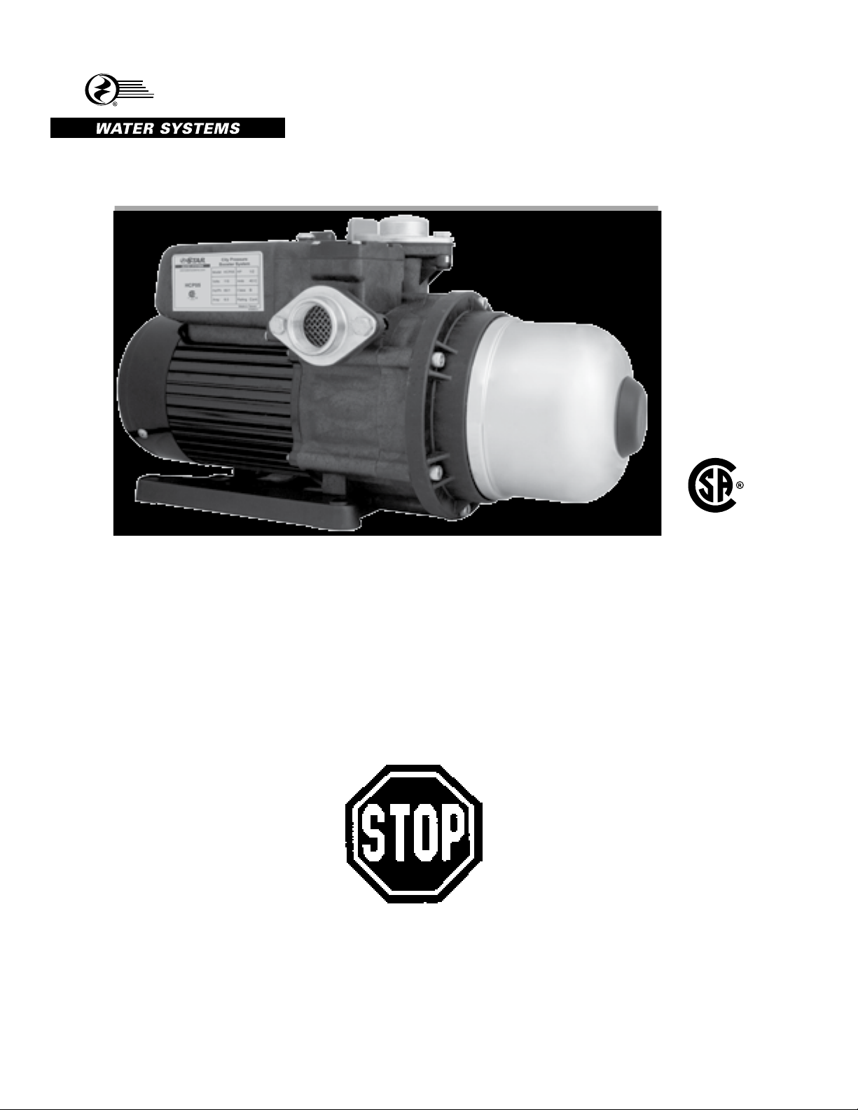
CITY PRESSURE BOOSTER PUMP
STAR
®
INSTRUCTION MANUAL
MODEL #
HCP05
C
NSF/ANSI 372
US
255405
For loose, missing or damaged parts, or if the unit does not
seem to be operating properly, please call before returning unit
to the place of purchase.
Phone No.: 1-800-742-5044
Service Hours:
Monday thru Friday - 7:30 am to 5:00 pm EST
SW0841 C
Page 2
GENERAL SAFETY INFORMATION
DANGER
PUMP SAFETY INFORMATION
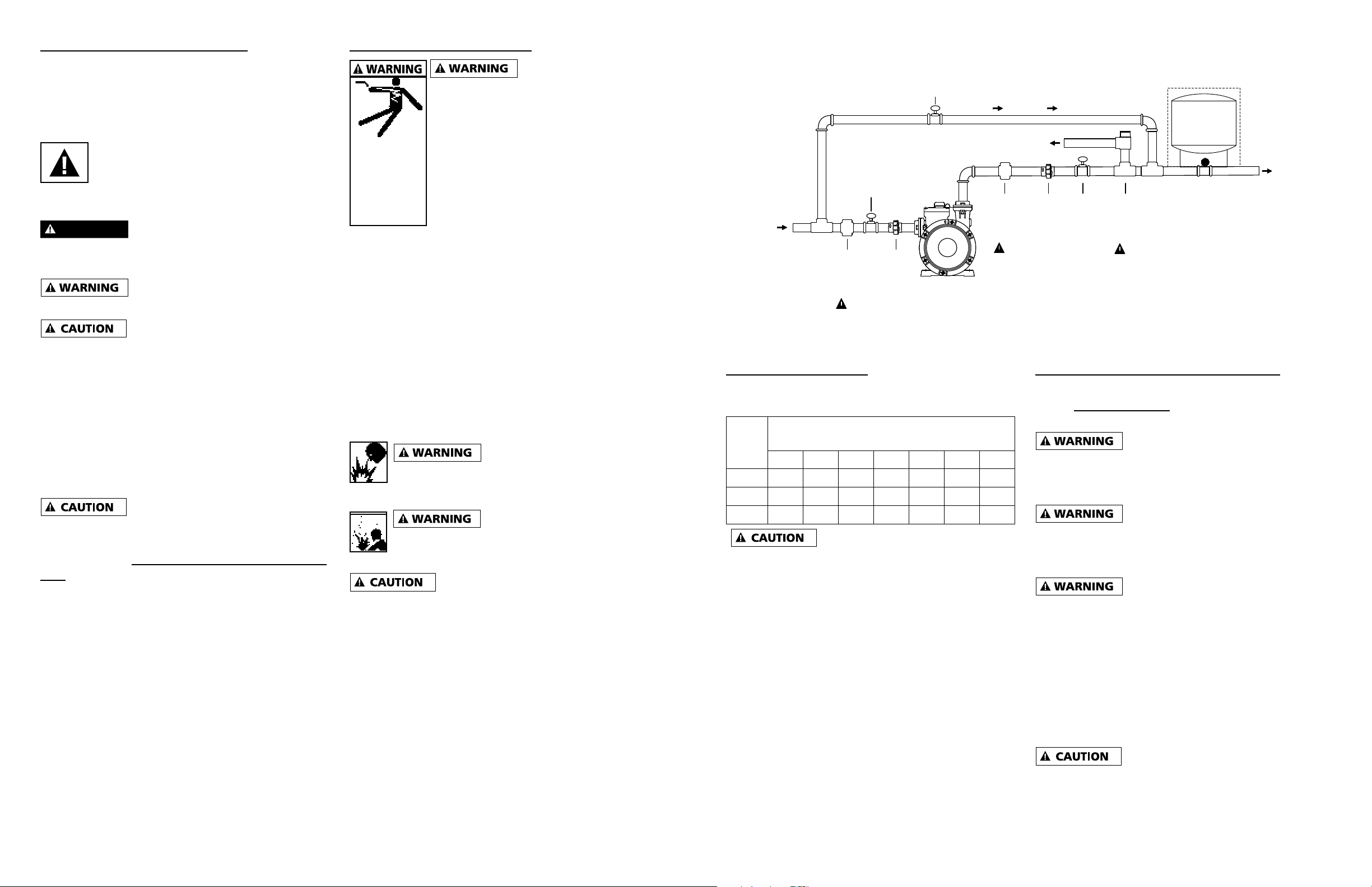
FIG 1 TYPICAL INSTALLATIONS
Please read and understand this manual before
attempting to assemble, operate or install this
product. For questions, please call customer service
at 1-800-742-5044 (7:30am - 5:00pm ESDT
Mon. - Fri.)
This is a SAFETY ALERT SYMBOL.
When you see this symbol on the pump or
in the manual, look for one of the
following signal words and be alert to the
potential for personal injury or property damage.
Warns of hazards that WILL cause
serious personal injury, death or major property
damage if ignored.
Warns of hazards that CAN cause
serious personal injury or death, if ignored.
Warns of hazards that MAY cause
minor personal injury, product or property damage
if ignored.
IMPORTANT: Indicates factors concerned with
operation, installation, assembly or maintenance
which could result in damage to the machine or
equipment if ignored.
NOTE: Indicates special instructions which are
important but are not related to hazards.
Customer Alert on Potential Water Damage: As
with any product subject to a continuous supply of
incoming water, a water alarm to monitor the pump
area is strongly recommended to alert the customer
to the potential for water damage which may result
from water line failure, product damage or incorrect
installation.
SHOCK HAZARD
1. Meet United States National
Electrical Code and local codes for
all wiring.
Hazardous
voltage. Can
shock, burn
or cause
death. Ground
pump before
connecting to
power supply.
2. Do not handle a pump or pump
motor with wet hands or when
standing on a wet or damp surface
or in water.
3. Follow wiring instructions in this
manual when connecting to power
lines.
4. Always disconnect power source before
performing any work on or near the motor or its
connected load.
5. Risk of electric shock - This pump has not been
investigated for use in swimming pool areas or
marine areas.
6. Protect electrical cord. Replace or repair
damaged or worn cords immediately.
7. To reduce the risk of electric shock, connect
only to a properly grounded, grounding-type
receptacle.
Do not use to pump
flammable or explosive fluids
such as gasoline, fuel oil, kerosene, etc. Do
not use in flammable and/or explosive environments.
Hazardous pressure! Install
pressure relief valve in
discharge pipe. Release all pressure on
system before working on any component.
GENERAL SAFETY
1. This pump has been evaluated to work with
water only.
2. Wear safety glasses when working with pumps.
3. Periodically inspect pump and system
components.
4. Do not insert finger or any object into pump or
motor openings.
5. Secure the discharge line before starting the
pump. An unsecured discharge line will whip,
possibly causing personal injury and/or property
damage or puncture.
6. Do not touch an operating motor or engine. They
are designed to operate at high temperatures.
Ball Valve #3
(Closed)
Ball
Valve
#1
City Main or Well
1" Dia. Suction
IN
(Open)
Adjustable
Pressure
Regulator
(APR)
#1
Union
Adjustable
Pressure
Regulator
(APR)
1/2 HP PERFORMANCE
See charts below for expected system pressure at
various incoming line pressure / flow rates.
HCP05 System Pressure (PSI)
Inlet
at Flow Rates (GPM)
PSI
3 6 9 12 15 18 21
10 44 39 32 25 17
20 54 49 42 35 27
30* 64 59 52 45 37
Do not exceed 30 input PSI for
P/N HCP05
*Note: Increase tank PSI (see FIG 3) if inlet PSI
will exceed preset tank setting 26 psi.
By-Pass
Drain
#2
Union
Ball
Valve
#2
(Open)
Pressure
Relief
Valve
(PRV)
#3
Optional
Water
Tank
Home or Irrigation
1" Dia. Discharge
IL1213
GENERAL PUMP INSTALLATION / SETUP (FIG 1)
City booster pump installation is shown per
FIG 1. During pump use, insure ball valves #1 and
#2 are open, and ball valve #3 is closed.
#1
An Adjustable Pressure
Regulator (APR#1) is required on the suction side of
the pump (see fig 1) if the incoming water pressure
can exceed the maximum input pressure.
#2
An Adjustable Pressure
Regulator (APR#2) is required on the Discharge
(See fig 1) to insure maximum water pressure does
not exceed local plumbing codes.
#3
A Pressure Relief Valve (PRV)
connected to a drain is required (see fig 1) to safe
guard plumbing from exceeding max pressures if the
Pressure Regulators fail. Typically the PRV would
be set 5 psi higher than the APR#2.
NOTE: Optional external water tank can be used to
decrease the on/off cycle rate of the pump system,
which can extend the life of the pump. (Typical tank
3 gallon draw down.) Set tank PSI equal to pump
tank PSI.
The entire system must be air and
water tight to maintain prime. Use thread tape on
all connections to insure no leaks. Hand tighten
all threads and then add additional half turn with
wrench.
OUT
2
95 North Oak Street • Kendallville, IN 46755 • © 2014 Star Water Systems. All rights reserved.
3
95 North Oak Street • Kendallville, IN 46755 • © 2014 Star Water Systems. All rights reserved.
Page 3

IL1307
NAMEPLATE DATA
Model HCP05
HP 1/2
Volts 115
HZ/Ph 60/1
Amp 6.0
Amb 40C
Class B
Rating Cont
LOCATION
Indoor/outdoor area – insure draining thru pressure
relief valve is available in order to avoid damage in
case of leakage.
Outdoor area – unit should be covered by a weather
proof housing, insure adequate ventilation.
PRIMING
After installation (with the pump OFF), open ball
valves #1 and #2, and slowly unthread the air relief
plug (FIG 2). Allow inlet water pressure to fill the
pump cavity and remove in-line air pockets. After
the pump cavity fills with water, retighten the air relief
plug.
FIG 2 PRIMING ILLUSTRATION
a. Open ball valves #1 and #2, close 3.
#3
#1
#2
b. Loosen the air relief plug.
Checking and Setting Tank PSI – Factory tank
PSI settings are 26 PSI (1/2 hp) and 36 PSI (1 hp).
If the inlet PSI is HIGHER than the factory settings,
increase the tank PSI to be approximately 5 PSI
higher than incoming pressure. To check the tank air
pressure, turn off power, open a tap on the discharge
line to release pressure from the pump, unscrew
the black plastic cover and apply a pressure gauge
to the valve as shown in FIG 3. Add tank pressure
as required, due to the tanks small volume, minimal
air volume is needed to increase tank pressure.
Reinstall black plastic cover.
FIG 3 SET TANK PRESSURE
GENERAL OPERATION GUIDELINES
• What Causes The Unit To Start? – The pump
will turn ON when the flow rate is greater
than 0.7 GPM or when the pressure output is
less than the pump pressure activation point
(approximately 25 psi - 1/2hp, 35 psi - 1hp).
• Dry Run Protection - After the unit recognizes
a continual low flow of water, the unit will
shut down to protect itself from running dry.
Hourly, it will turn on to sample the water flow
requirements, and return to shut down if running
dry. The home owner can fix the run dry issue
and return the pump to normal operation by
unplugging the pump for 5 seconds.
• Dead Head Protection - If there is no water
demand (discharge is shut off), the unit will shut
down to protect the pump from damage. Once
water flow is restarted, the pump will re-start the
power automatically.
FREEZING (OR REMOvING PUMP FOR
MAINTENANCE)
The pump and all piping must
be protected from freezing. If freezing weather
is forecast, and the unit will be exposed to
temperatures less than 32ºF (0ºC), remove the pump
by closing off ball valves #1 and #2, (see FIG. 1) and
removing the pump, using the union connections.
Store pump in a heated area. Open ball valve #3 to
allow city water to pass forward if desired. Insure
the piping is adequately protected from the cold
environment.
OPERATING CONDITIONS
Ambient temperature range 32ºF (0ºC) to 104ºF
(40ºC).
c. Ensure water lls
chamber from city water.
Replace plug immediately
to avoid excess moisture
on pump.
Torque : 26 in-lb
in b
26
d. Tighten the air
relief plug.
IL1207
If unit is shut down for extended
period of time or air enters into the system, it may be
necessary to repeat the above priming instructions to
insure the internal pump cavity is running with water
to avoid dry running damage to the internal seals.
NOTE: If using optional water tank (FIG. 1), set both
tanks to the same pressures.
• Rapid Cycle Protection – If the unit cycles
repeatedly on/off, the unit will shut down to
protect the pump life. The optional water tank
not maintaining pressure could be a potential
cause. Hourly, it will turn on to sample the water
flow requirements, and return to shut down if the
problem persists. The home owner can fix the
concern and return the pump to normal operation
by unplugging the pump for 5 seconds.
4
95 North Oak Street • Kendallville, IN 46755 • © 2014 Star Water Systems. All rights reserved.
5
95 North Oak Street • Kendallville, IN 46755 • © 2014 Star Water Systems. All rights reserved.
Page 4

TROUBLESHOOTING
Before ANY work with the pump, SHUT OFF the electrical supply and ball valves #1 and #2 to
prevent electrical shock and water damage.
MAINTENANCE REqUIREMENTS
• Pressure Tank Charge – should be checked
every 3 months to confirm tank air pressure. See
FIG 3 for description to check air pressure.
• Pump Suction Inlet Screen – if internal debris
blocks or restricts the inlet suction screen (FIG
5), manually clean with hands.
FIG 5 – INLET SCREEN
Problem Cause Correction
Pump does not start or shuts
down,
No power supply. Connect the electricity supply.
Incorrect voltage. Pump is 115 Volt only.
It will not start with 230V supply.
Incorrectly plumbed. Confirm FIG 1 installation is correct.
Confirm ball valves #1 and #2 are open
in suction and discharge. Confirm ball
valve #3 is closed on bypass.
Blocked inlet Check if pump suction inlet screen is
blocked. See FIG 5.
Insufficient water supply Insure water source is providing
sufficient water.
Pump starts when no water is
consumed.
Pipe leaking. Insure all threads have 3 wraps of
Teflon tape + hand tight + 1/2 turn with
wrench.
Tank pressure is low. See FIG 3 to check and add air
pressure to the tank.
Air in the system. Insure all threads have 3 wraps of
teflon tape + hand tight + 1/2 turn with
wrench. Re-prime unit.
Pump does not shut down
when water is not consumed.
Blocked check valve. See FIG 4. Confirm check valve is free
of debris and functions freely.
Note – tank pressure should be set
approximately 5 psi higher than the expected
incoming pressure.
• Internal Check Valve – if Teflon tape or debris
enters into the pump cavity, the operation of the
internal check valve can be restricted. This may
create an erratic or poor performance with the
pump. To clean the check valve see FIG 4.
FIG 4 – INTERNAL CHECK vALvE
a. Remove the air relief
port and top cover
b. Conrm the spring
and check valve are
free of debris
IL1310
6
95 North Oak Street • Kendallville, IN 46755 • © 2014 Star Water Systems. All rights reserved.
a. Reassemble the top
cover and air relief
port
IL1308
7
95 North Oak Street • Kendallville, IN 46755 • © 2014 Star Water Systems. All rights reserved.
Page 5

OUTLINE / DIMENSIONAL SIZE
C
Inlet
NPT 1"
5.71
3.35
7.74
1.773.96
Outlet
NPT 1"
8.88
6.89
A
DIMENSIONS CHART C
Model A (in.) B (in.) C (in.)
B
HCP05 13.56 5.43 5.63
LIMITED WARRANTY
This product is warranted for one year from the date
of purchase. Subject to the conditions hereinafter
set forth, the manufacturer will repair or replace to
the original consumer, any portion of the product
which proves defective due to defective materials or
workmanship. To obtain warranty service, contact
the dealer from whom the product was purchased.
The manufacturer retains the sole right and option
to determine whether to repair or replace defective
equipment, parts or components. Damage due to
conditions beyond the control of the manufacturer is
not covered by this warranty.
THIS WARRANTY WILL NOT APPLY: (a) To defects
or malfunctions resulting from failure to properly install,
operate or maintain the unit in accordance with printed
instructions provided; (b) to failures resulting from
abuse, accident or negligence or use of inappropriate
chemicals or additives in the water; (c) to normal
maintenance services and the parts used in connection
with such service; (d) to units which are not installed
in accordance with normal applicable local codes,
ordinances and good trade practices; and (e) the unit is
used for purposes other than for what it was designed
and manufactured.
4-Ø0.4
5.12
6.3
L1212
THE WARRANTY PROVIDED HEREIN IS IN LIEU
OF ALL OTHER EXPRESS WARRANTIES, AND
MAY NOT BE EXTENDED OR MODIFIED BY
ANYONE. ANY IMPLIED WARRANTIES SHALL
BE LIMITED TO THE PERIOD OF THE LIMITED
WARRANTY AND THEREAFTER ALL SUCH IMPLIED
WARRANTIES ARE DISCLAIMED AND EXCLUDED.
THE MANUFACTURER SHALL NOT, UNDER ANY
CIRCUMSTANCES, BE LIABLE FOR INCIDENTAL,
CONSEQUENTIAL OR SPECIAL DAMAGES, SUCH
AS, BUT NOT LIMITED TO DAMAGE TO, OR LOSS
OF, OTHER PROPERTY OR EQUIPMENT, LOSS
OF PROFITS, INCONVENIENCE , OR OTHER
INCIDENTAL OR CONSEQUENTIAL DAMAGES OF
ANY TYPE OR NATURE. THE LIABILITY OF THE
MANUFACTURER SHALL NOT EXCEED THE PRICE
OF THE PRODUCT UPON WHICH SUCH LIABILITY
IS BASED.
This warranty gives you specific legal rights, and you
may have other rights which vary from state to state.
Some states do not allow limitations on duration
of implied warranties or exclusion of incidental or
consequential damages, so the above limitations may
not apply to you.
RETURN OF WARRANTED COMPONENTS: Any item
to be repaired or replaced under this warranty must be
returned to the manufacturer at Kendallville, Indiana or
such other place as the manufacturer may designate,
freight prepaid.
95 North Oak Street • Kendallville, IN 46755 • © 2014 Star Water Systems. All rights reserved.
WARRANTY VALID IN CANADA AND MEXICO.
8
 Loading...